EP0456564B1 - Power steering and limited slip differential system - Google Patents
Power steering and limited slip differential system Download PDFInfo
- Publication number
- EP0456564B1 EP0456564B1 EP91401174A EP91401174A EP0456564B1 EP 0456564 B1 EP0456564 B1 EP 0456564B1 EP 91401174 A EP91401174 A EP 91401174A EP 91401174 A EP91401174 A EP 91401174A EP 0456564 B1 EP0456564 B1 EP 0456564B1
- Authority
- EP
- European Patent Office
- Prior art keywords
- steering
- pressure
- pressure oil
- cylinder
- air
- Prior art date
- Legal status (The legal status is an assumption and is not a legal conclusion. Google has not performed a legal analysis and makes no representation as to the accuracy of the status listed.)
- Expired - Lifetime
Links
- 230000004044 response Effects 0.000 claims description 58
- 238000006243 chemical reaction Methods 0.000 claims description 45
- 238000002347 injection Methods 0.000 claims description 23
- 239000007924 injection Substances 0.000 claims description 23
- 230000007246 mechanism Effects 0.000 claims description 19
- 238000005452 bending Methods 0.000 claims description 10
- 230000008878 coupling Effects 0.000 claims description 9
- 238000010168 coupling process Methods 0.000 claims description 9
- 238000005859 coupling reaction Methods 0.000 claims description 9
- 238000011144 upstream manufacturing Methods 0.000 claims description 6
- 230000001965 increasing effect Effects 0.000 description 9
- 238000004088 simulation Methods 0.000 description 7
- 230000008859 change Effects 0.000 description 6
- 238000003825 pressing Methods 0.000 description 5
- 238000010586 diagram Methods 0.000 description 4
- 230000000694 effects Effects 0.000 description 4
- 230000001133 acceleration Effects 0.000 description 3
- 238000004364 calculation method Methods 0.000 description 3
- 230000009699 differential effect Effects 0.000 description 3
- 230000002708 enhancing effect Effects 0.000 description 3
- 238000011835 investigation Methods 0.000 description 3
- 230000009467 reduction Effects 0.000 description 3
- 239000000725 suspension Substances 0.000 description 3
- 206010021703 Indifference Diseases 0.000 description 2
- 230000003247 decreasing effect Effects 0.000 description 2
- 230000001934 delay Effects 0.000 description 2
- 238000007599 discharging Methods 0.000 description 2
- 238000000034 method Methods 0.000 description 2
- 238000004904 shortening Methods 0.000 description 2
- 238000012546 transfer Methods 0.000 description 2
- 241000239290 Araneae Species 0.000 description 1
- 238000013459 approach Methods 0.000 description 1
- 238000006757 chemical reactions by type Methods 0.000 description 1
- 238000004590 computer program Methods 0.000 description 1
- 238000012937 correction Methods 0.000 description 1
- 238000013016 damping Methods 0.000 description 1
- 238000006073 displacement reaction Methods 0.000 description 1
- 230000006870 function Effects 0.000 description 1
- 230000000977 initiatory effect Effects 0.000 description 1
- 239000000047 product Substances 0.000 description 1
- 230000035485 pulse pressure Effects 0.000 description 1
- 239000013589 supplement Substances 0.000 description 1
- 230000001629 suppression Effects 0.000 description 1
- 230000003746 surface roughness Effects 0.000 description 1
- 238000012795 verification Methods 0.000 description 1
Images


Classifications
-
- B—PERFORMING OPERATIONS; TRANSPORTING
- B60—VEHICLES IN GENERAL
- B60K—ARRANGEMENT OR MOUNTING OF PROPULSION UNITS OR OF TRANSMISSIONS IN VEHICLES; ARRANGEMENT OR MOUNTING OF PLURAL DIVERSE PRIME-MOVERS IN VEHICLES; AUXILIARY DRIVES FOR VEHICLES; INSTRUMENTATION OR DASHBOARDS FOR VEHICLES; ARRANGEMENTS IN CONNECTION WITH COOLING, AIR INTAKE, GAS EXHAUST OR FUEL SUPPLY OF PROPULSION UNITS IN VEHICLES
- B60K23/00—Arrangement or mounting of control devices for vehicle transmissions, or parts thereof, not otherwise provided for
- B60K23/04—Arrangement or mounting of control devices for vehicle transmissions, or parts thereof, not otherwise provided for for differential gearing
-
- B—PERFORMING OPERATIONS; TRANSPORTING
- B62—LAND VEHICLES FOR TRAVELLING OTHERWISE THAN ON RAILS
- B62D—MOTOR VEHICLES; TRAILERS
- B62D6/00—Arrangements for automatically controlling steering depending on driving conditions sensed and responded to, e.g. control circuits
- B62D6/04—Arrangements for automatically controlling steering depending on driving conditions sensed and responded to, e.g. control circuits responsive only to forces disturbing the intended course of the vehicle, e.g. forces acting transversely to the direction of vehicle travel
-
- B—PERFORMING OPERATIONS; TRANSPORTING
- B62—LAND VEHICLES FOR TRAVELLING OTHERWISE THAN ON RAILS
- B62D—MOTOR VEHICLES; TRAILERS
- B62D7/00—Steering linkage; Stub axles or their mountings
- B62D7/06—Steering linkage; Stub axles or their mountings for individually-pivoted wheels, e.g. on king-pins
- B62D7/14—Steering linkage; Stub axles or their mountings for individually-pivoted wheels, e.g. on king-pins the pivotal axes being situated in more than one plane transverse to the longitudinal centre line of the vehicle, e.g. all-wheel steering
- B62D7/15—Steering linkage; Stub axles or their mountings for individually-pivoted wheels, e.g. on king-pins the pivotal axes being situated in more than one plane transverse to the longitudinal centre line of the vehicle, e.g. all-wheel steering characterised by means varying the ratio between the steering angles of the steered wheels
- B62D7/159—Steering linkage; Stub axles or their mountings for individually-pivoted wheels, e.g. on king-pins the pivotal axes being situated in more than one plane transverse to the longitudinal centre line of the vehicle, e.g. all-wheel steering characterised by means varying the ratio between the steering angles of the steered wheels characterised by computing methods or stabilisation processes or systems, e.g. responding to yaw rate, lateral wind, load, road condition
Definitions
- This invention relates to a power steering and limited slip differential system suitable for vehicles, in particular, for trucks and buses.
- phase lag and gain of a vehicle's handling response increase with vehicle speed. Excessive phase lag will cause delay in the vehicle reaching the driver's intended course, resulting in oversteering, while excessive gain will intensify the oversteering, making the vehicle weave.
- phase lag will also increase the time required for disturbance, such as road surface roughness, to be transmitted to the driver's hand on the steering wheel as a response, delaying corrective steering and producing steering wheel weave.
- disturbance such as road surface roughness
- the phase lag magnitude in particular can reach four or five times that of passenger cars.
- vehicle's controllability and stability have to be investigated from both sides, in that the vehicle response performance in association with driver's handling and the vehicle response performance in association with disturbances such as those caused by roughness of the road surface.
- Fig. 2 shows an example of the response characteristic of a truck and bus.
- the truck is equipped with a front engine and leaf suspensions, while the bus with a rear engine and air suspensions, and the gain and phase lag of the truck are smaller than those of the bus. Further the subjective judgement of the truck is better than the bus.
- phase lag is assumed to belong to the time constant property.
- approach to an aimed course by a driver delays so that an oversteering is caused, and when the gain is much larger, the oversteering is amplified so that the vehicle weaves.
- the problems arising from the physiological ability difference can be compensated by reducing the time constant in the steering system.
- the irregularity of the road surface causes displacement of the axles and the chassis in succession, such is sensed by the driver, and thereafter the driver's corrective steering begins.
- a smaller delay until the corrective steering and greater damping of the disturbances are desirable, however beyond this, if the disturbances can be intercepted at the inlet so as not to permit their entries, such is considered the best way.
- the time lag in the steering system occupies 50% of the total. Further, with regard to the chassis system, the time lag of the buses is larger than that of trucks, the reasons of which are considered due to the influence of such as their suspension structure differences and weight allotment differences to the front and rear axles.
- truck and bus employ common steering systems so that with regard to the time lag in their steering systems there are no difference.
- the disturbances be intercepted at the inlet.
- the countermeasures thereto are the compliance steering control of the rear wheels and the torque split control between the right and left rear wheels, in particular, in case of the rigid rear axle structure with leaf springs which is employed in many large commercial vehicles, the torque split control is preferable.
- US Patent N°. 4, 796, 714 shows a power steering system in which an auxiliary booster is driven simultaneously with a main booster when a large vehicle is at a stop or is running at low speed, and assumes a free state when the vehicle is running at high speed. This system does not enhance handling response performance and disturbance response performance to enhance the control stability of the vehicle.
- the pressure of the compensating pressure oil which is injected into the reaction chambers of the directional control valve and the auxiliary booster is increased by the injection pressure control valve in response to the rise of the vehicle speed and the increase of the differential value in the steering effort to perform compensation for the steering delay in the handling which reduces the phase lag without increasing the gain
- the air pressure of the clutch control air cylinder, with the air pressure control valve is reduced in response to the increase of the vehicle speed and the increase of the front wheel steering angle in a low speed region, is raised in response to the increase of the vehicle speed and the decrease of the front wheel steering angle in a high speed region, is raised in response to the slip of one side of the rear wheels in a low vehicle speed, and is reduced in response to the slip of the both sides of the rear wheels in a low vehicle speed so as to limit differential action and to increase and decrease driving force which suppress interference to the running along the course of the vehicle, help escape the vehicle from the road surface having a small road surface
- Figs. 6, 13, 14, 15, 16 and 17 show the concrete embodiment of the power steering and limited slip differential system 10 according to the present invention which is applied to a rear-mounted engine bus.
- the system 10 is composed of a power steering arrangement 11 and a limited slip differential arrangement 12,
- the power steering arrangement 11 includes such as a main booster 14, an auxiliary booster 15, a directional control valve 16, a pressure oil setting valve 17, an injection pressure control valves 18, 19, a reaction adjusting valve 20, a hydraulic pump 21 provided with an oil reservoir, and a steering wheel 23 which provides a steering input to the directional control valve 16,
- the limited slip differential arrangement 12 includes such as a differential gear mechanism 25 combined with a reduction gear mechanism 91, a friction clutch 26, a clutch control air cylinder 27, an air pressure control valve 28, an air tank 29, and a safety valve 30, and the power steering arrangement 11 and limited slip differential arrangement 12 are assembled to facilitate an electronic control with a microcomputer 13.
- the microcomputer 13 electrically connects at its input side with a vehicle speed sensor 31, a steering effort sensor 32, a wheel rotation sensors 33, 34, 35, 36, a pressure sensor 37, a manual switch 38 and a brake switch 39 and electrically connects at its output side with the solenoid coils (not shown) of the injection pressure control valves 18, 19, the electric actuator (not shown) of the air pressure control valve 28 respectively, controls the power steering arrangement 11 so as to perform a steering operation in which a steering delay compensation is added which reduces the phase lag without increasing the gain, and as well as controls the limited slip differential arrangement 12 so as to limit the differential action and to increase and decrease the driving force (transferred torque), further, concurrently, with the power steering arrangement 11 to lighten the power steering effort during stationary steering and a low speed running, and to change the handling response feeling into a level of somewhat heavier steering effort during a high speed running.
- the main booster 14 incorporates the directional control valve 16, generates steering effort for front wheels 121, 122 and is constructed into an integral type which enables manual steering.
- the main booster 14 includes a cylinder body 40 inside of which a cylinder bore 41 is formed, a rack piston 42 fitted in the cylinder bore 41 permitting slidable reciprocation to form a pair of cylinder chambers 43, 44 in the cylinder bore 41 and a sector gear (not shown) engaging the rack of the rack piston 42, and is link-coupled to the front wheels 121, 122 via a pitman arm 45 fixedly coupled to the shaft (not shown) of the sector gear and a link mechanism 46, of course, oil ports 47, 48 which open to the corresponding cylinder chambers 43, 44 are formed at the cylinder body 40.
- the auxiliary booster 15 is constructed into a double acting type cylinder which generates an auxiliary steering effort for the front wheels 121, 123.
- the auxiliary booster 15 includes a cylinder body 49 inside of which a cylinder bore (not shown) is formed, a piston (not shown) fitted in the cylinder bore permitting slidable reciprocation to form a pair of cylinder chambers (not shown) in the cylinder bore, and a piston rod 50 one end of which is fixedly connected to the piston and the other end of which extends out of the cylinder body permitting pulling in and out thereof, and the other end of the piston rod 50 is link-coupled to the front wheels 121, 122 via link mechanism 46a.
- oil ports 51, 52 which open to the corresponding pair of cylinder chambers are formed at the cylinder body 49.
- the directional control valve 16 is provided with a pair of reaction chambers 56, 57, is incorporated into the cylinder body 40 of the main booster 14, and is constructed into a hydraulic reaction type spool valve in which a spool 55 is shifted by a shift shaft (not shown) secured to the input axis (not shown) which is connected to the steering shaft 24, and the operating pressure oil is direction-controlled which is supplied from the hydraulic pump 21 to the main booster 14 via a supply side pressure oil piping 74 and concurrently is exhausted from the main booster 14 to the oil reservoir 22 via a return side oil pressure piping 75.
- the directional control valve 16 includes a valve body 53 inside of which a valve bore 54 is provided and incorporated into the cylinder body 40 of the main booster 14, the spool 55 fitted in the valve bore 54 permitting slidable reciprocation to form the pair of reaction chambers 56, 57, and the spool 55 is slidably moved inside the valve bore 54 by the steering wheel 23 via the steering shaft 24, input axis, and the shift shaft and direction-controls the operating pressure oil so as to flow from the hydraulic pump 21 to either of the cylinder chambers 43, 44 in the main booster 14 via the supply side pressure oil piping 74 and concurrently from another of the cylinder chambers 43, 44 in the main booster 14 to the oil reservoir 22 via the returning pressure oil piping 75 respectively, and in that instance, the amount of steering in the main booster 14 is fed back.
- a pump port 58, tank ports 59, 60, cylinder ports 61, 62, reaction ports 63, 64, and injection ports 65, 66 which open to the valve bore 54 are formed at predetermined positions, the pump port 58 is connected to the supply side pressure oil piping 74 and the tank ports 59, 60 to the returning side pressure oil piping 75 respectively and further, the cylinder ports 61, 62 are connected to the corresponding oil ports 47, 48 via communicating channels 67, 68.
- reaction communicating ports 69, 70 are formed which supply the operating pressure oil into either of the reaction chambers 56, 57 from the hydraulic pump 21 in response to the shift direction of the spool 55 and as well as return the operating pressure oil from another of the reaction chambers 56, 57 to the oil reservoir 22, when the spool 55 is shifted within the valve bore 54.
- the pressure oil setting valve 17 is disposed in the supply side pressure oil piping 74 at the upstream side of the directional control valve 16, and sets the pressure of the operating pressure oil supplied to the main booster 14 and the pressure of the compensating pressure oil supplied to the auxiliary booster 15 and the chambers 56, 57 of the directional control valve 16.
- the injection pressure control valves 18, 19 are linear solenoid valves and are disposed in compensating pressure oil pipings 76, 77, 78, 79, 80, 81, 82, 83 which connect the pair of cylinder chambers of the auxiliary booster 15 and the pair of reaction chambers of the directional control valve 16 to the hydraulic pump 21 and the oil reservoir 22, and further, the solenoid coils (not shown) thereof are electrically connected to the output side of the microcomputer 13.
- the injection pressure control valves 18, 19 carry out valve operation by the current provided from the microcomputer 13 in response to the running speed of the bus and steering effort applied to the steering wheel 23 at the beginning of steering and of steering back, and at the beginning of steering inject the compensating pressure oil into the cylinder chambers of the auxiliary booster 15 and the reaction chambers 56, 57 of the directional control valve 16 in their predetermined direction, and at the time of steering back inject the compensating pressure oil into the cylinder chambers of the auxiliary booster 15 and the reaction chambers 56, 57 of the directional control valve 16 in their predetermined direction, and as well control the pressure of the compensating pressure oil injected.
- the injection pressure control valves 18, 19 connect the cylinder chambers of the auxiliary booster 15 to the oil reservoir 22 and as well interrupts the reaction chambers of the directional control valve 16 from the hydraulic pump 21 and the oil reservoir 22.
- injection pressure control valves 18, 19 have such a structure that the compensating pressure oil is injected into the cylinder chambers of the auxiliary booster 15 and the reaction chambers 56, 57 of the directional control valve 16, orifices 71, 72 are disposed in the compensating pressure oil pipings 80, 81 in view of the relationship between the cylinder chambers of the auxiliary booster 15 and the reaction chambers 56, 57 of the directional control valve 16.
- the reaction adjustment valve 20 is disposed in a bypass channel 73 communicating each other the pair of reaction chambers 56, 57 of the directional control valve 16, and the electric actuator thereof is electrically connected to the microcomputer 13.
- the electric actuator is driven by the current provided by the microcomputer 13, and the orifice thereof is adjusted so as to change the handling response in such a manner that the steering effort is felt lighter during a stationary steering and a low speed running and the steering effort is felt heavier during a high speed running.
- the differential gear mechanism 25 is incorporated with the reduction gear mechanism 91 which includes a drive pinion 92 and a ring gear 93 engaged each other in the differential carrier 84, and includes four differential pinions 88, 88 and a pair of differential side gears 89, 89 disposed in a differential case 86 in association with the reduction gear mechanism.
- the differential pinions 88, 88 are rotatably fitted at the both ends of spider 90, on the other hand, the differential side gears 89, 89 are spline-connected to driving wheel axles 119, 120 for the rear wheels 123, 124 and are engaged with the differential pinions 88, 88.
- the friction clutch 26 is disposed between the differential case 86 and the driving wheel axle 119, and is assembled to include the bore 94 formed in the differential case 86, clutch ring 96 forming the bore 94 of the differential case 86 spline-connected to the driving wheel axle 119 into a ring chamber 95, many external gear clutch plates 97 and internal gear clutch plates 98 alternatively arranged in the ring chamber 95 and a pressure ring 99 pushing the external and internal gear clutch plates 97, 98.
- this friction clutch 26 is assembled in a position in which the external gear clutch plates 97 is spline-coupled with the differential case 86, and the internal gear clutch plates 98, with the clutch ring 96 respectively, the differential action of the differential gear mechanism is limited and the transfer torque of the driving wheel axles 119, 120 is controlled in increasing and decreasing direction.
- the clutch control air cylinder 27 is incorporated into the differential case 86, and connected to the air tank 29 via pressurized air piping 111, and controls the friction clutch 26 to engage and disengage by charging and discharging the operating pressurized air supplied from the air tank 29.
- This clutch control air cylinder 27 is embodied into an internal cylinder guiding type structure which includes a ring cylinder 100 which opens to the ring chamber 95 and is formed in the differential case 86, and a ring piston 102 which is fitted in the ring cylinder 100 while facing to the pressure ring 99 and permitting slidable reciprocation to form cylinder chamber 101 in the ring cylinder 100, and is assembled in such a manner that an air port 103 which opens to the cylinder chamber 101 is connected to the pressurized air piping 111 via a pressure air coupling 104, the operating pressurized air is charged from the air tank 29 to the cylinder chamber 101 and discharged from the cylinder chamber 101 to the air and by pressing and separating the external and internal gear clutch plates 97, 98 via the pressure ring 99, the clutch engagement and disengagement operation of the friction clutch 26 is carried out.
- the pressure air coupling 104 is assembled together with a sealed slip ring 105 fitted onto a boss 87 of the differential case 86 so as to permit relative rotational movement thereto and fitted into a ring gear boss 85 of a differential carrier 84 so as to prevent rotation thereto, and an air lead pipe 106 connecting the shield slip ring 105 to the pressurized air piping 111 outside the differential carrier 84, and further the air lead pipe 106 comprises a pipe connector 107 and is connected to the pressurized air piping 111 via the pipe connector 107.
- the air pressure control valve 28 is disposed in the pressurized air piping 111 which connects clutch control air cylinder 27 with the air tank 29, is driven by the current provided from the microcomputer 13 in response to the vehicle speed and the front wheel steering angle, and in response to the slipping at one side and both sides of the rear wheels, charges and discharges the operating compressed air to and from the clutch control air cylinder 27, and controls the air pressure of the clutch control air cylinder 27.
- This air pressure control valve 28 is formed of a combination of a normally closed type two way solenoid valve 109 and normally open type two way solenoid valve 110, in particular, the normally open type two way solenoid valve 110 is disposed downstream the normally closed type two way solenoid valve 109 and is combined therewith each other, further the solenoid coils (not shown) of the normally closed type and normally open type two way solenoid valves 109 and 110 are electrically connected to the output side of the microcomputer 13.
- the normally closed type two way solenoid valve 109 is used for supplying the operating compressed air from the air tank 29 to the clutch control air cylinder 27, on the other hand, the normally open type two way solenoid valve 110 is for discharging the operating compressed air from the clutch control air cylinder 27 to the air.
- the vehicle speed sensor 31 is disposed at the diesel engine (not shown) mounted on the bus.
- the steering effort sensor 32 is for detecting the force applied to the steering wheel 23, and is incorporated in the steering wheel.
- the steering effort sensor 32 includes a bending beam of which root portion is secured at the side of the rim core 113 and the top portion is fitted into a groove 118 at the side of the rim sheath 115 so as to represent the sliding amount by bending, and an-electromagnetic inductor type sensor (not shown) for detecting the bending of the bending beam 117, and the electromagnetic inductor type sensor is electrically connected to the input side of the microcomputer 13.
- the wheel rotation sensors 33, 34, 35, 36 are respectively disposed corresponding to the front wheels and the rear wheels, and are electrically connected to the microcomputer 13.
- the pressure sensor 37 is combined with the air pressure control valve 28 at the position where the air pressure of the clutch control air cylinder 27 can be sensed, and is electrically connected to the microcomputer 13.
- the pressure oil namely, the compensating pressure oil be supplied to the power cylinder not only at the beginning of steering but also at the time of steering back in the form of pulse like pressure oil, if it were supplied at the beginning of steering only, the gain would deteriorate, namely increase (see Fig. 9).
- the pulse width and the pulse pressure of the pulse like pressure oil in response to both variations of the steering effort applied to the steering wheel and the differential value thereof, and the indifference of the steering operation is eliminated by applying the pulse like pressure oil correspondingly to the reaction chambers of the directional control valve.
- the vehicle speed is detected from the front wheel revolution speed, the steering angle from the revolution speed difference between the right and left front wheels and the slip rate of the rear wheels from the revolution speed difference between the front and rear wheels, based upon the detected values, the torque Td is controlled so as to increase with vehicle speed in a small steering angle region for enhancing stable straight running, and to be zero so as to maintain the lateral force gripping of the tires in the spin limit, and is further controlled so as to increase when one side of the rear wheels happens to slip, and to decrease when both sides of the rear wheels happen to slip, in order to improve prompt start performance on the road having a small road surface friction coefficient ⁇ and to reduce side slip.
- Fig. 14 The structure of the steering system is shown in Fig. 14 the upstream pressure is always kept higher by 5 Kg/cm 2 (pressurized oil) than that in the circuit with the pressure oil setting valve 17.
- the steering effort applied to the rim sheath 115 of the steering wheel 23 is calculated by the microcomputer 13 based on the bending and the spring constant of the bending beam 117.
- the electromagnetic inductor type sensor built-in in the steering wheel 23 detects thereof, the injection pressure control valves 18, 19 are selectively opened by the current selectively provided from the microcomputer 13, the compensating pressure oil is selectively injected into the pair of cylinder chambers of the auxiliary booster 15 and the actual steering of the front wheels 121, 122 begins while bypassing the system.
- the compensating pressure oil is also injected into the reaction chambers 56, 57 of the directional control valve 16, through the supply of this compensating pressure oil to the auxiliary booster 15, the steering indifference caused by the pull from the steering wheel 23 is prevented.
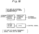
- the steering effort sensor 32 being located at a closer position to the driver than the rim core 113 which is the inertia mass of the steering wheel 23, detects the true steering effort without being affected by the inertia and as well is adapted to respond only to the steering effort by the driver through constitution unlike by to be affected by high frequency disturbances such as kick-back by means of the mass-damper effect of the rim core 113 and high response active low pass filter provided in the side of the microcomputer 13 (see Fig. 16).
- the structure of the differential system is shown in Fig. 17, in this differential system, the friction clutch 26 is incorporated in the differential case 86, and the clutch control air cylinder 27 is also disposed in the differential case 86 in association with the friction clutch 26, and thereby with the operating compressed air supplied to the clutch control air cylinder 27 the ring piston 102 is pressed to the many external gear and internal gear clutch plates 97, 98 of the friction clutch 26 via the pressure ring 99 to generate the torque limiting the differential operation in the differential system.
- the steering responsive control, the disturbance responsive control, and the speed sensitive control are carried out at the same time in association with each other.
- the steering effort sensor 32 detects the steering effort, and provides the steering effort in the form of an electrical signal to the microcomputer 13 and simultaneously the vehicle speed is provided in the form of an electrical signal from the vehicle speed sensor 31 to the microcomputer 13, accordingly, the microcomputer 13 controls the current flowing through the solenoid coils of the injection pressure control valves 18, 19 to selectively open and close the injection pressure control valves 18, 19 in response to the signals inputted from the steering effort sensor 32 and the vehicle speed sensor 31.
- the compensating pressure oil is selectively supplied to the pair of cylinder chambers of the auxiliary booster 15 from the upstream side of the pressure oil setting valve 17 in the front wheels, at the same time, the compensating pressure oil is selectively injected into the reaction chambers 56, 57 of the directional control valve 16 to generate the steering response, thereby controlling the increase of the yaw rate and the phase lag without increasing the gain during steering operation.
- the compensating pressure oil is supplied in the steering direction into the pair of cylinder chambers of the auxiliary booster 15 and the pair of reaction chambers of the directional control valve 16 in the form of pulse like pressure oil for a period of 0.075 wavelength from the beginning of the steering, and further, when the steering wheel 23 is steered back, the compensating pressure oil supplied in the steering back direction into the pair of cylinder chambers of the auxiliary booster 15 and the pair of reaction chambers of the directional control valve 16 in the form of pulse like pressure oil for a period of 0.25 wavelength from the beginning of the steering back.
- the disturbance responsive control is carried out based upon the vehicle speed, steering angle and rear wheel slip rate determined by the microcomputer 13.
- the wheel revolution sensors 33, 34, 35, 36 detect the revolution speed of the front wheels 121, 122 and the rear wheels 123, 124 and provide thereof to the microcomputer in the form of electrical signals, and then the microcomputer 13 calculates and determines the vehicle speed from the revolution speed of the front wheels, the steering angle from the revolution speed difference between the right and left front wheels, and the slip rate of the rear wheels 123, 124 from the revolution speed difference between the front wheels 121, 122 and the rear wheels 123, 124.
- the normal close type and normal open type two way solenoid valves 109, 110 in the air pressure control valve 28 are open and close controlled by the microcomputer 13 in response to the increase of the vehicle-speed, increase of the front wheel steering angle and the air pressure of the clutch control air cylinder 27, the operating compressed air is supplied from the air tank 29 to the clutch control air cylinder 27 and is discharged from the clutch control air cylinder 27 to the air to reduce the air pressure in the clutch control air cylinder, to lower the force of the clutch control air cylinder 27 pressing the friction clutch 26 and thereby to decrease the friction torque generated in the friction clutch 26 for limiting the differential movement of the differential gear mechanism 25.
- the differential movement limiting torque in the differential gear mechanism 25 is controlled to facilitate a smooth lane change by buses.
- the air pressure control valve 28 is open and close controlled by the microcomputer 13 as described above in response to the increase of the vehicle speed, increase of the front wheel steering angle and the air pressure of the clutch control air cylinder 27 to raise the air pressure in the clutch control air cylinder 27, to increase the force of the clutch control air cylinder pressing the friction clutch 26 and thereby to increase the friction torque generated in the friction clutch 26 for limiting the differential movement of the differential gear mechanism 25.
- the differential movement limiting torque in the differential gear mechanism 25 is controlled to stabilize the straight running of the bus and to maintain the lateral force gripping of the tire.
- the air pressure control valve 28 is open and close controlled by the microcomputer 13 to raise the air pressure in the clutch control air cylinder 27, to increase the force of the clutch control air cylinder 27 pressing the friction clutch 26 and thereby to increase the torque generated in the friction clutch 26 for limiting the differential movement of the differential gear mechanism 25.
- the air pressure control valve 28 is open and close controlled by the microcomputer 13 to lower the air pressure in the clutch control air cylinder 27, to reduce the force of the clutch control air cylinder 27 pressing the friction clutch 26 and thereby to decrease the torque generated in the friction clutch 26 for limiting the differential movement of the differential gear mechanism 25.
- the bus performs a smooth start and runs on the road having a low road surface friction coefficient ⁇ .
- the microcomputer 13 controls the current flowing through the electric actuator of the reaction adjustment valve 20 in response to the signals from the vehicle speed sensor 31, and adjusts the orifice of the reaction adjustment valve 20 in response to the increase of the vehicle speed to change the resistance to the pressure oil flowing between the reaction chambers 56, 57 of the directional control valve 16 and to thereby regulate the steering effort lighter during a stationary steering and a low speed running and somewhat heavier during a high speed running so as to obtain a sufficient handling response feeling.
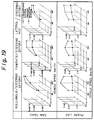
- Fig. 19 the gain and phase lag are illustrated in relation to the vehicle speed and the lateral acceleration.
- Fig. 20 shows steering angles and their frequency on a highway.
- the steering angle frequency distribution of this system 10 is reduced above 50% in terms of standard deviation in comparison with that of the conventional system.
- the power steering and limited slip differential system includes a main booster which generates a steering effort for front wheels; an auxiliary booster which generates a compensation steering effort for the front wheels; a directional control valve which has pair of reaction chambers and which controls the direction of operating pressure oil which is supplied from a hydraulic pump to the main booster and concurrently discharged from the main booster to an oil reservoir; a pressure oil setting valve which sets the pressure of the operating pressure oil supplied to the main booster, and the pressure of compensating pressure oil supplied to the auxiliary booster and the reaction chambers of the directional control valve; an injection pressure control valve which injects the compensating pressure oil into the reaction chambers of the directional control valve and the auxiliary booster in response to a vehicle speed and the steering effort at the beginning of steering and steering back during the handling, and concurrently controls the pressure of the injected compensating pressure oil; a friction clutch disposed between the differential case of a differential gear mechanism and a driving wheel axle for rear wheels; a clutch control air cylinder for coupling and decoup
Description
- This invention relates to a power steering and limited slip differential system suitable for vehicles, in particular, for trucks and buses.
- Generally, phase lag and gain of a vehicle's handling response increase with vehicle speed. Excessive phase lag will cause delay in the vehicle reaching the driver's intended course, resulting in oversteering, while excessive gain will intensify the oversteering, making the vehicle weave.
- Further, high phase lag will also increase the time required for disturbance, such as road surface roughness, to be transmitted to the driver's hand on the steering wheel as a response, delaying corrective steering and producing steering wheel weave. In the case of trucks and buses, the phase lag magnitude in particular can reach four or five times that of passenger cars.
- Still further, expressways in midnight are as if huge belt conveyers filled up with groups of trucks. These trucks are flowing towards the metropolitan Tokyo and arrive at wholesale markets etc. before dawn. A between car distance in these truck groups is generally short and the speed thereof is high. Further, highway bus services between cities are spotlighted. Because of their advantages such as inexpensive fares and easiness, living space with a high sense and high quality, and attentive services, not only the night bus services which were understood at the beginning to supplement railway train services, but also day time highway bus services are increasing. As such, on one hand, the demand for high speed and long distance services by the trucks and buses are active, however, on the other hand, in particular, with regard to trucks, a shortage of truck drivers is serious, and in addition, age of the drivers has been increasing.
- For these reasons, there appears an indication of woman driver expansion.
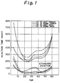
- Further, the higher the speed of a vehicle is, the more the response performance thereof reduces. Still further, physiological ability relating to driving skill of advanced age drivers and woman drivers are relatively low in comparison with that of young man (see Fig. 1).
- Therefore, a system is desired which realizes a compensation for the decrease in the response performance at high speed region and the physiological ability difference of the drivers within the vehicle. Moreover, large sized vehicles which necessitate relatively-wide space on the running road in comparison with passenger cars even have to be provided with a more excellent response performance than passenger cars.
- Further, with regard to desirable vehicle response characteristics, vehicle's controllability and stability have to be investigated from both sides, in that the vehicle response performance in association with driver's handling and the vehicle response performance in association with disturbances such as those caused by roughness of the road surface.
- At first, with regard to handling response characteristic, there are reports, one defines factor Tβ corresponding to the product of the time constant and yaw gain and indicates that the smaller the factor is, the higher is the subjective judgement of drivers, and the other indicates that there is an optimum region of course tracking characteristic in a range of small time constants and of certain amounts of yaw acceleration gain.
- These date concern with passenger cars, however these tendencies are similar to in trucks and buses.
- Fig. 2 shows an example of the response characteristic of a truck and bus.
- The truck is equipped with a front engine and leaf suspensions, while the bus with a rear engine and air suspensions, and the gain and phase lag of the truck are smaller than those of the bus. Further the subjective judgement of the truck is better than the bus.
- These gain and phase lag increase in response to increase of the vehicle speed and thereby burdens to drivers increase. This suggests that a desirable handling response region will be in a direction reducing both the gain and phase lag smaller than those of now.
- This tendency meets with the previous tendency with regard to the passenger car data, when the phase lag is assumed to belong to the time constant property. When the phase lag is large, approach to an aimed course by a driver delays so that an oversteering is caused, and when the gain is much larger, the oversteering is amplified so that the vehicle weaves. Still further the problems arising from the physiological ability difference can be compensated by reducing the time constant in the steering system.
- Nextly, with regard to disturbance response characteristic, it is desirable to reduce the effects caused by disturbances as much as possible. For example, the irregularity of the road surface causes displacement of the axles and the chassis in succession, such is sensed by the driver, and thereafter the driver's corrective steering begins. A smaller delay until the corrective steering and greater damping of the disturbances are desirable, however beyond this, if the disturbances can be intercepted at the inlet so as not to permit their entries, such is considered the best way.
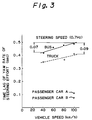
- Further, with regard to the handling response, when the handling response performance of trucks and buses are compared with those of passenger cars, there is a significant difference in connection with the phase lag, which are very large in trucks and buses (see Fig. 3). For analyzing what causes make the phase lag such large, the time lag from the initiation of steering operation to the beginning of the course change of the vehicle was measured along its transfer route (see Figs. 4 and 7).
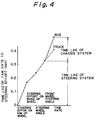
- As the result, it was found out that the time lag in the steering system occupies 50% of the total. Further, with regard to the chassis system, the time lag of the buses is larger than that of trucks, the reasons of which are considered due to the influence of such as their suspension structure differences and weight allotment differences to the front and rear axles.
- These truck and bus employ common steering systems so that with regard to the time lag in their steering systems there are no difference.
- Further, several studies reported to have carried out to shorten the time lag in the steering system which amounts to 60% among the total time lag. Some of these went further to suggest specific system structures but failed to reach practical uses.
- Two reasons are presumed for the failures. One is presumed that the phase lag has been shortened, however concurrently the gain gets large, thereby the steering wheel becomes sensitive and the handling feeling is deteriorated. The other is presumed that since the mechanical coupling between the steering wheel and the front wheels has been disconnected, problems in connection with safety are unsolved.
- In view of the above, such measures are required that reduce phase lag without increasing the time lag and are applicable without disconnecting the mechanical coupling.
- On the other hand, with regard to the disturbance response, as indicated above, the disturbances be intercepted at the inlet. In other words, it is desirable to intercept the entering of disturbance at the tires from which the disturbances intrude. The countermeasures thereto are the compliance steering control of the rear wheels and the torque split control between the right and left rear wheels, in particular, in case of the rigid rear axle structure with leaf springs which is employed in many large commercial vehicles, the torque split control is preferable.
- US Patent N°. 4, 796, 714 shows a power steering system in which an auxiliary booster is driven simultaneously with a main booster when a large vehicle is at a stop or is running at low speed, and assumes a free state when the vehicle is running at high speed. This system does not enhance handling response performance and disturbance response performance to enhance the control stability of the vehicle.
- It is therefore an object and a problem of the present invention to provide a power steering and limited slip differential system which enhances handling response performance and disturbance response performance to enhance the control stability of vehicles.
- In connection with the above described object and problem, in a power steering and limited slip differential system as described in US Patent N°. 4, 796, 714, including a main booster which generates a steering effort for front wheels, a directional control valve which has at least one reaction chamber and which controls the direction of operating pressure oil which is supplied from a hydraulic pump to the main booster and concurrently discharged from the main booster to an oil reservoir, an auxiliary booster which generates a compensating steering effort for the front wheels; the present invention resides in the inclusion of a friction clutch disposed between the differential case of a differential gear mechanism and a driving wheel axle for rear wheels, the directional valve having a pair of reaction chambers,
a pressure oil setting valve which sets the pressure of the operating pressure oil supplied to the main booster, and the pressure of compensating pressure oil supplied to the auxiliary booster and the reaction chambers of the directional control valve;
an injection pressure control valve which injects the compensating pressure oil into the reaction chambers of the directional control valve and the auxiliary booster in response to a vehicle speed and the steering effort at the beginning of steering and steering back in the handling, and concurrently controls the pressure of the injected compensating pressure oil;
a clutch control air cylinder for coupling and decoupling the friction clutch; and
an air pressure control valve which charges and discharges operating compressed air to and from the clutch control air cylinder in response to the vehicle speed and the steering angle of the front wheels, and further in response to the slipping of one side and the both sides of the rear wheels, and controls the air pressure of the clutch control air cylinder. - Further, in the power steering and limited slip differential system according to the present invention, the pressure of the compensating pressure oil which is injected into the reaction chambers of the directional control valve and the auxiliary booster is increased by the injection pressure control valve in response to the rise of the vehicle speed and the increase of the differential value in the steering effort to perform compensation for the steering delay in the handling which reduces the phase lag without increasing the gain, and as well as, the air pressure of the clutch control air cylinder, with the air pressure control valve, is reduced in response to the increase of the vehicle speed and the increase of the front wheel steering angle in a low speed region, is raised in response to the increase of the vehicle speed and the decrease of the front wheel steering angle in a high speed region, is raised in response to the slip of one side of the rear wheels in a low vehicle speed, and is reduced in response to the slip of the both sides of the rear wheels in a low vehicle speed so as to limit differential action and to increase and decrease driving force which suppress interference to the running along the course of the vehicle, help escape the vehicle from the road surface having a small road surface friction coefficient µ, and reduce side slips.
- To help understanding of the invention, one specific concrete embodiment thereof will now be described with reference to the accompanying drawings in which:-
- Fig. 1 is a graph illustrating difference in response time to light and sound stimulus by gender and age,
- Fig. 2 is a graph illustrating difference in yaw rate response between a truck and bus,
- Fig. 3 is a graph illustrating difference in time lag of yaw rate response in a truck, bus and passenger car,
- Fig. 4 is a graph illustrating the share of time lag by a steering system and a chassis,
- Fig. 5 is a view illustrating a vehicle model,
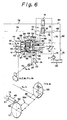
- Fig. 6 is a schematic diagram of the steering system of the power steering and limited slip differential system according to the present invention,
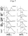
- Fig. 7 is graphs illustrating for comparison and verification on the data of an actual vehicle and the result of simulation,
- Fig. 8 is graphs explaining study with regard to pressure oil injection timing by simulation,
- Fig. 9 is a graph explaining study with regard to pressure oil injection width by simulation,
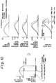
- Fig. 10 is graphs illustrating final simulation result with regard to the pressure oil injection timing and width,
- Fig. 11 is a graph illustrating actuating circumstances of the differential system under actual road conditions,
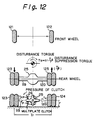
- Fig. 12 is a diagram illustrating disturbance suppression effect by the limited slip differential torque,
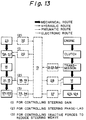
- Fig. 13 is a diagram illustrating the control system,
- Fig. 14 is a schematic overview of the power steering and limited slip differential system according to the present invention,
- Fig. 15 is a plane view partially cross-sectioned steering wheel,
- Fig. 16 is a diagram for explaining the mass-damper effect and the active low pass filter,
- Fig. 17 is a cross sectional view illustrating the differential system of the power steering and limited slip differential system according to the present invention,
- Fig. 18 is graphs illustrating data with regard to lane change,
- Fig. 19 is graphs illustrating effects on gain and phase lag, and
- Fig. 20 is a graph illustrating steering correction frequency.
- Figs. 6, 13, 14, 15, 16 and 17 show the concrete embodiment of the power steering and limited
slip differential system 10 according to the present invention which is applied to a rear-mounted engine bus. - The
system 10 is composed of apower steering arrangement 11 and a limited slipdifferential arrangement 12, thepower steering arrangement 11 includes such as amain booster 14, anauxiliary booster 15, adirectional control valve 16, a pressureoil setting valve 17, an injectionpressure control valves reaction adjusting valve 20, ahydraulic pump 21 provided with an oil reservoir, and asteering wheel 23 which provides a steering input to thedirectional control valve 16, on the other hand, the limited slipdifferential arrangement 12 includes such as adifferential gear mechanism 25 combined with a reduction gear mechanism 91, a friction clutch 26, a clutchcontrol air cylinder 27, an airpressure control valve 28, anair tank 29, and asafety valve 30, and thepower steering arrangement 11 and limited slipdifferential arrangement 12 are assembled to facilitate an electronic control with amicrocomputer 13. Themicrocomputer 13 electrically connects at its input side with a vehicle speed sensor 31, asteering effort sensor 32, awheel rotation sensors pressure sensor 37, amanual switch 38 and a brake switch 39 and electrically connects at its output side with the solenoid coils (not shown) of the injectionpressure control valves pressure control valve 28 respectively, controls thepower steering arrangement 11 so as to perform a steering operation in which a steering delay compensation is added which reduces the phase lag without increasing the gain, and as well as controls the limited slipdifferential arrangement 12 so as to limit the differential action and to increase and decrease the driving force (transferred torque), further, concurrently, with thepower steering arrangement 11 to lighten the power steering effort during stationary steering and a low speed running, and to change the handling response feeling into a level of somewhat heavier steering effort during a high speed running. - The
main booster 14 incorporates thedirectional control valve 16, generates steering effort forfront wheels - The
main booster 14 includes acylinder body 40 inside of which a cylinder bore 41 is formed, arack piston 42 fitted in the cylinder bore 41 permitting slidable reciprocation to form a pair ofcylinder chambers rack piston 42, and is link-coupled to thefront wheels pitman arm 45 fixedly coupled to the shaft (not shown) of the sector gear and alink mechanism 46, of course,oil ports corresponding cylinder chambers cylinder body 40. - The
auxiliary booster 15 is constructed into a double acting type cylinder which generates an auxiliary steering effort for thefront wheels - The
auxiliary booster 15 includes acylinder body 49 inside of which a cylinder bore (not shown) is formed, a piston (not shown) fitted in the cylinder bore permitting slidable reciprocation to form a pair of cylinder chambers (not shown) in the cylinder bore, and apiston rod 50 one end of which is fixedly connected to the piston and the other end of which extends out of the cylinder body permitting pulling in and out thereof, and the other end of thepiston rod 50 is link-coupled to thefront wheels oil ports cylinder body 49. - The
directional control valve 16 is provided with a pair ofreaction chambers 56, 57, is incorporated into thecylinder body 40 of themain booster 14, and is constructed into a hydraulic reaction type spool valve in which aspool 55 is shifted by a shift shaft (not shown) secured to the input axis (not shown) which is connected to the steeringshaft 24, and the operating pressure oil is direction-controlled which is supplied from thehydraulic pump 21 to themain booster 14 via a supply side pressure oil piping 74 and concurrently is exhausted from themain booster 14 to theoil reservoir 22 via a return side oil pressure piping 75. - The
directional control valve 16 includes a valve body 53 inside of which a valve bore 54 is provided and incorporated into thecylinder body 40 of themain booster 14, thespool 55 fitted in the valve bore 54 permitting slidable reciprocation to form the pair ofreaction chambers 56, 57, and thespool 55 is slidably moved inside the valve bore 54 by thesteering wheel 23 via the steeringshaft 24, input axis, and the shift shaft and direction-controls the operating pressure oil so as to flow from thehydraulic pump 21 to either of thecylinder chambers main booster 14 via the supply side pressure oil piping 74 and concurrently from another of thecylinder chambers main booster 14 to theoil reservoir 22 via the returning pressure oil piping 75 respectively, and in that instance, the amount of steering in themain booster 14 is fed back. - Further, in the valve body 53 of the
directional control valve 16, apump port 58,tank ports reaction ports 63, 64, andinjection ports 65, 66 which open to the valve bore 54 are formed at predetermined positions, thepump port 58 is connected to the supply side pressure oil piping 74 and thetank ports oil ports channels - Still further, in the
spool 55 of thedirectional control valve 16,reaction communicating ports reaction chambers 56, 57 from thehydraulic pump 21 in response to the shift direction of thespool 55 and as well as return the operating pressure oil from another of thereaction chambers 56, 57 to theoil reservoir 22, when thespool 55 is shifted within the valve bore 54. - The pressure
oil setting valve 17 is disposed in the supply side pressure oil piping 74 at the upstream side of thedirectional control valve 16, and sets the pressure of the operating pressure oil supplied to themain booster 14 and the pressure of the compensating pressure oil supplied to theauxiliary booster 15 and thechambers 56, 57 of thedirectional control valve 16. - The injection
pressure control valves pressure oil pipings auxiliary booster 15 and the pair of reaction chambers of thedirectional control valve 16 to thehydraulic pump 21 and theoil reservoir 22, and further, the solenoid coils (not shown) thereof are electrically connected to the output side of themicrocomputer 13. - Further, the injection
pressure control valves microcomputer 13 in response to the running speed of the bus and steering effort applied to thesteering wheel 23 at the beginning of steering and of steering back, and at the beginning of steering inject the compensating pressure oil into the cylinder chambers of theauxiliary booster 15 and thereaction chambers 56, 57 of thedirectional control valve 16 in their predetermined direction, and at the time of steering back inject the compensating pressure oil into the cylinder chambers of theauxiliary booster 15 and thereaction chambers 56, 57 of thedirectional control valve 16 in their predetermined direction, and as well control the pressure of the compensating pressure oil injected. Of course, in a normal condition, the injectionpressure control valves auxiliary booster 15 to theoil reservoir 22 and as well interrupts the reaction chambers of thedirectional control valve 16 from thehydraulic pump 21 and theoil reservoir 22. - Still further, since the injection
pressure control valves auxiliary booster 15 and thereaction chambers 56, 57 of thedirectional control valve 16,orifices pressure oil pipings 80, 81 in view of the relationship between the cylinder chambers of theauxiliary booster 15 and thereaction chambers 56, 57 of thedirectional control valve 16. - The
reaction adjustment valve 20 is disposed in abypass channel 73 communicating each other the pair ofreaction chambers 56, 57 of thedirectional control valve 16, and the electric actuator thereof is electrically connected to themicrocomputer 13. - Further, in the
reaction adjustment valve 20, the electric actuator is driven by the current provided by themicrocomputer 13, and the orifice thereof is adjusted so as to change the handling response in such a manner that the steering effort is felt lighter during a stationary steering and a low speed running and the steering effort is felt heavier during a high speed running. - The
differential gear mechanism 25 is incorporated with the reduction gear mechanism 91 which includes adrive pinion 92 and aring gear 93 engaged each other in thedifferential carrier 84, and includes fourdifferential pinions differential case 86 in association with the reduction gear mechanism. Of course, thedifferential pinions spider 90, on the other hand, the differential side gears 89, 89 are spline-connected to drivingwheel axles rear wheels differential pinions - The friction clutch 26 is disposed between the
differential case 86 and thedriving wheel axle 119, and is assembled to include the bore 94 formed in thedifferential case 86,clutch ring 96 forming the bore 94 of thedifferential case 86 spline-connected to thedriving wheel axle 119 into aring chamber 95, many external gearclutch plates 97 and internal gearclutch plates 98 alternatively arranged in thering chamber 95 and apressure ring 99 pushing the external and internal gearclutch plates clutch plates 97 is spline-coupled with thedifferential case 86, and the internal gearclutch plates 98, with theclutch ring 96 respectively, the differential action of the differential gear mechanism is limited and the transfer torque of thedriving wheel axles - The clutch
control air cylinder 27 is incorporated into thedifferential case 86, and connected to theair tank 29 viapressurized air piping 111, and controls the friction clutch 26 to engage and disengage by charging and discharging the operating pressurized air supplied from theair tank 29. - This clutch
control air cylinder 27 is embodied into an internal cylinder guiding type structure which includes aring cylinder 100 which opens to thering chamber 95 and is formed in thedifferential case 86, and aring piston 102 which is fitted in thering cylinder 100 while facing to thepressure ring 99 and permitting slidable reciprocation to formcylinder chamber 101 in thering cylinder 100, and is assembled in such a manner that anair port 103 which opens to thecylinder chamber 101 is connected to the pressurized air piping 111 via apressure air coupling 104, the operating pressurized air is charged from theair tank 29 to thecylinder chamber 101 and discharged from thecylinder chamber 101 to the air and by pressing and separating the external and internal gearclutch plates pressure ring 99, the clutch engagement and disengagement operation of the friction clutch 26 is carried out. - Of course, the
pressure air coupling 104 is assembled together with a sealedslip ring 105 fitted onto aboss 87 of thedifferential case 86 so as to permit relative rotational movement thereto and fitted into aring gear boss 85 of adifferential carrier 84 so as to prevent rotation thereto, and anair lead pipe 106 connecting theshield slip ring 105 to the pressurized air piping 111 outside thedifferential carrier 84, and further theair lead pipe 106 comprises apipe connector 107 and is connected to the pressurized air piping 111 via thepipe connector 107. - The air
pressure control valve 28 is disposed in the pressurized air piping 111 which connects clutchcontrol air cylinder 27 with theair tank 29, is driven by the current provided from themicrocomputer 13 in response to the vehicle speed and the front wheel steering angle, and in response to the slipping at one side and both sides of the rear wheels, charges and discharges the operating compressed air to and from the clutchcontrol air cylinder 27, and controls the air pressure of the clutchcontrol air cylinder 27. - This air
pressure control valve 28 is formed of a combination of a normally closed type twoway solenoid valve 109 and normally open type twoway solenoid valve 110, in particular, the normally open type twoway solenoid valve 110 is disposed downstream the normally closed type twoway solenoid valve 109 and is combined therewith each other, further the solenoid coils (not shown) of the normally closed type and normally open type twoway solenoid valves microcomputer 13. - Further, in this air
pressure control valve 28, the normally closed type twoway solenoid valve 109 is used for supplying the operating compressed air from theair tank 29 to the clutchcontrol air cylinder 27, on the other hand, the normally open type twoway solenoid valve 110 is for discharging the operating compressed air from the clutchcontrol air cylinder 27 to the air. - The vehicle speed sensor 31 is disposed at the diesel engine (not shown) mounted on the bus.
- The
steering effort sensor 32 is for detecting the force applied to thesteering wheel 23, and is incorporated in the steering wheel. - Further, as shown in Fig. 15, since the
steering wheel 23 includeshub 112, arim core 113 integrated with thehub 112 viaspoke 114, arim sheath 115 covering therim core 113 via aroller 116 so as to permit a slight free slidable rotation in the steering direction and is assembled therewith, thesteering effort sensor 32 includes a bending beam of which root portion is secured at the side of therim core 113 and the top portion is fitted into agroove 118 at the side of therim sheath 115 so as to represent the sliding amount by bending, and an-electromagnetic inductor type sensor (not shown) for detecting the bending of thebending beam 117, and the electromagnetic inductor type sensor is electrically connected to the input side of themicrocomputer 13. - The
wheel rotation sensors microcomputer 13. - The
pressure sensor 37 is combined with the airpressure control valve 28 at the position where the air pressure of the clutchcontrol air cylinder 27 can be sensed, and is electrically connected to themicrocomputer 13. - Since the power steering and limited
slip differential system 10 has been assembled as explained above, nextly, computer program which enables to simulate thesystem 10 was prepared for determining an optimum control, and the simulation result was compared and verified with actual vehicle data, thereafter control method were investigated for reducing the phase lag without increasing the gain. - For this simulation the vehicle model as shown in Fig. 5 and the steering system model as shown in Fig. 6 were used.
- Further, equations of motion and hydraulic pressure calculation equations were formulated, and such were solved by using CSSL (Continuous System Simulation Language). The results of the calculation showed nearly the same tendency as the actually measured data so that the investigation on the optimum control was carried out using the results.
- This investigation on the optimum control will be explained hereinbelow.
- At first, control of the steering system is explained, as will be understood from Fig. 7, generation of hydraulic pressure in the power steering arrangement delays by 0.1 to 0.2 sec. after the application of the steering effort to the steering wheel. When the hydraulic pressure is immediately generated after sensing steering signals, shortening of the delay at least by 0.1 sec. is enabled. This shortening by 0.1 sec. is, as will be understood from Fig. 7, equivalent to the fact that the delay level of the bus is improved to that of the truck, in other words, the delay level at a vehicle speed of 100 Km/h to that below a vehicle speed of 60 Km/h. With such in mind, several control methods were investigated through calculation by using the model shown in Fig. 6, as the result it was found out that such control is the optimum in which when the force applied to the rim of the steering wheel is detected, the pressure oil is supplied to the power cylinder in advance to the steering operation via the mechanical system, to begin the actual steering of the front wheels, simultaneously the pressure oil is also supplied to the pressure oil reaction chambers of the directional control valve to generate the steering reaction (see Fig. 8).
- It is important that the pressure oil, namely, the compensating pressure oil be supplied to the power cylinder not only at the beginning of steering but also at the time of steering back in the form of pulse like pressure oil, if it were supplied at the beginning of steering only, the gain would deteriorate, namely increase (see Fig. 9).
- Further, it was found out that there is an optimum width of the pulse like pressure oil, in case that the pressure of the pulse is 0.5 MPa, 0.075 wavelength pulse is effective for the pulse width at the beginning of steering and 0.25 wavelength pulse for that at the time of steering back (see Fig. 10). Further, the reason for concurrent supply of the pressure oil to also the pressure oil reaction chambers is to prevent the steering response from disappearing due to steering pull caused by the pressure oil supplied to the power cylinder.
- Still further, it is preferable to determine the pulse width and the pulse pressure of the pulse like pressure oil in response to both variations of the steering effort applied to the steering wheel and the differential value thereof, and the indifference of the steering operation is eliminated by applying the pulse like pressure oil correspondingly to the reaction chambers of the directional control valve.
- On the other hand, with regard to the control in the differential system, when a vehicle is running straight on a flat road, theoretically, no differential operation is needed, however actually the differential operation still activates (see Fig. 11). When torque Td resisting the differential operation is applied, torque Ts (see Fig. 12), which is obtained by multiplying the torque Td divided by the tire radius by the rear axle tread, functions to suppress disturbances which interfere with the running of the vehicle along the course.
- Accordingly, the vehicle speed is detected from the front wheel revolution speed, the steering angle from the revolution speed difference between the right and left front wheels and the slip rate of the rear wheels from the revolution speed difference between the front and rear wheels, based upon the detected values, the torque Td is controlled so as to increase with vehicle speed in a small steering angle region for enhancing stable straight running, and to be zero so as to maintain the lateral force gripping of the tires in the spin limit, and is further controlled so as to increase when one side of the rear wheels happens to slip, and to decrease when both sides of the rear wheels happen to slip, in order to improve prompt start performance on the road having a small road surface friction coefficient µ and to reduce side slip.
- Based upon the investigation results on the optimum control thus obtained, the control of the steering system for enhancing the steering response performance and the control of the differential system for enhancing the disturbance response performance are integrated to realize this system 10 (see Fig. 13).
- The structure of the steering system is shown in Fig. 14 the upstream pressure is always kept higher by 5 Kg/cm2 (pressurized oil) than that in the circuit with the pressure
oil setting valve 17. - The steering effort applied to the
rim sheath 115 of thesteering wheel 23 is calculated by themicrocomputer 13 based on the bending and the spring constant of thebending beam 117. When the steering effort is applied on the steering wheel, the electromagnetic inductor type sensor built-in in thesteering wheel 23 detects thereof, the injectionpressure control valves microcomputer 13, the compensating pressure oil is selectively injected into the pair of cylinder chambers of theauxiliary booster 15 and the actual steering of thefront wheels - Almost simultaneously, the compensating pressure oil is also injected into the
reaction chambers 56, 57 of thedirectional control valve 16, through the supply of this compensating pressure oil to theauxiliary booster 15, the steering indifference caused by the pull from thesteering wheel 23 is prevented. - The
steering effort sensor 32, being located at a closer position to the driver than therim core 113 which is the inertia mass of thesteering wheel 23, detects the true steering effort without being affected by the inertia and as well is adapted to respond only to the steering effort by the driver through constitution unlike by to be affected by high frequency disturbances such as kick-back by means of the mass-damper effect of therim core 113 and high response active low pass filter provided in the side of the microcomputer 13 (see Fig. 16). - On the other hand, the structure of the differential system is shown in Fig. 17, in this differential system, the friction clutch 26 is incorporated in the
differential case 86, and the clutchcontrol air cylinder 27 is also disposed in thedifferential case 86 in association with the friction clutch 26, and thereby with the operating compressed air supplied to the clutchcontrol air cylinder 27 thering piston 102 is pressed to the many external gear and internal gearclutch plates pressure ring 99 to generate the torque limiting the differential operation in the differential system. - Nextly, the operation of the power steering and limited
slip differential system 10 designed as described above is explained. - In this power steering and limited
slip differential system 10, the steering responsive control, the disturbance responsive control, and the speed sensitive control are carried out at the same time in association with each other. - In the steering responsive control, when a steering effort is applied to the
steering wheel 23, thesteering effort sensor 32 detects the steering effort, and provides the steering effort in the form of an electrical signal to themicrocomputer 13 and simultaneously the vehicle speed is provided in the form of an electrical signal from the vehicle speed sensor 31 to themicrocomputer 13, accordingly, themicrocomputer 13 controls the current flowing through the solenoid coils of the injectionpressure control valves pressure control valves steering effort sensor 32 and the vehicle speed sensor 31. - Since the injection
pressure control valves cylinder chambers main booster 14 by valve changing over of thedirectional control valve 16 via the mechanical system, the compensating pressure oil is selectively supplied to the pair of cylinder chambers of theauxiliary booster 15 from the upstream side of the pressureoil setting valve 17 in the front wheels, at the same time, the compensating pressure oil is selectively injected into thereaction chambers 56, 57 of thedirectional control valve 16 to generate the steering response, thereby controlling the increase of the yaw rate and the phase lag without increasing the gain during steering operation. Of course, in this steering response control, when thesteering wheel 23 is steered, the compensating pressure oil is supplied in the steering direction into the pair of cylinder chambers of theauxiliary booster 15 and the pair of reaction chambers of thedirectional control valve 16 in the form of pulse like pressure oil for a period of 0.075 wavelength from the beginning of the steering, and further, when thesteering wheel 23 is steered back, the compensating pressure oil supplied in the steering back direction into the pair of cylinder chambers of theauxiliary booster 15 and the pair of reaction chambers of thedirectional control valve 16 in the form of pulse like pressure oil for a period of 0.25 wavelength from the beginning of the steering back. - On the other hand, the disturbance responsive control is carried out based upon the vehicle speed, steering angle and rear wheel slip rate determined by the
microcomputer 13. For that purpose, thewheel revolution sensors front wheels rear wheels microcomputer 13 calculates and determines the vehicle speed from the revolution speed of the front wheels, the steering angle from the revolution speed difference between the right and left front wheels, and the slip rate of therear wheels front wheels rear wheels - Now, assuming that the bus is running in a low speed region, the normal close type and normal open type two
way solenoid valves pressure control valve 28 are open and close controlled by themicrocomputer 13 in response to the increase of the vehicle-speed, increase of the front wheel steering angle and the air pressure of the clutchcontrol air cylinder 27, the operating compressed air is supplied from theair tank 29 to the clutchcontrol air cylinder 27 and is discharged from the clutchcontrol air cylinder 27 to the air to reduce the air pressure in the clutch control air cylinder, to lower the force of the clutchcontrol air cylinder 27 pressing the friction clutch 26 and thereby to decrease the friction torque generated in the friction clutch 26 for limiting the differential movement of thedifferential gear mechanism 25. - Accordingly, the differential movement limiting torque in the
differential gear mechanism 25 is controlled to facilitate a smooth lane change by buses. - Further, assuming that the bus is running in a high speed region, the air
pressure control valve 28 is open and close controlled by themicrocomputer 13 as described above in response to the increase of the vehicle speed, increase of the front wheel steering angle and the air pressure of the clutchcontrol air cylinder 27 to raise the air pressure in the clutchcontrol air cylinder 27, to increase the force of the clutch control air cylinder pressing the friction clutch 26 and thereby to increase the friction torque generated in the friction clutch 26 for limiting the differential movement of thedifferential gear mechanism 25. - Accordingly, the differential movement limiting torque in the
differential gear mechanism 25 is controlled to stabilize the straight running of the bus and to maintain the lateral force gripping of the tire. - Further, when the one side of the
rear wheels pressure control valve 28 is open and close controlled by themicrocomputer 13 to raise the air pressure in the clutchcontrol air cylinder 27, to increase the force of the clutchcontrol air cylinder 27 pressing the friction clutch 26 and thereby to increase the torque generated in the friction clutch 26 for limiting the differential movement of thedifferential gear mechanism 25. - Thereafter, when the one side slip of the
rear wheels pressure control valve 28 is open and close controlled by themicrocomputer 13 to lower the air pressure in the clutchcontrol air cylinder 27, to reduce the force of the clutchcontrol air cylinder 27 pressing the friction clutch 26 and thereby to decrease the torque generated in the friction clutch 26 for limiting the differential movement of thedifferential gear mechanism 25. - Accordingly, the bus performs a smooth start and runs on the road having a low road surface friction coefficient µ.
- Further, in the speed sensitive control, the
microcomputer 13 controls the current flowing through the electric actuator of thereaction adjustment valve 20 in response to the signals from the vehicle speed sensor 31, and adjusts the orifice of thereaction adjustment valve 20 in response to the increase of the vehicle speed to change the resistance to the pressure oil flowing between thereaction chambers 56, 57 of thedirectional control valve 16 and to thereby regulate the steering effort lighter during a stationary steering and a low speed running and somewhat heavier during a high speed running so as to obtain a sufficient handling response feeling. - The results of these controls performed as described above are shown in Fig. 18 through Fig. 20.
- In Fig. 19, the gain and phase lag are illustrated in relation to the vehicle speed and the lateral acceleration.
- The data of this
system 10 at a vehicle speed of 100 Km/h is improved equivalent to those of the conventional system below 60 Km/h. - Fig. 20 shows steering angles and their frequency on a highway.
- The steering angle frequency distribution of this
system 10 is reduced above 50% in terms of standard deviation in comparison with that of the conventional system. - As will be understood from the above since the power steering and limited slip differential system according to the present invention includes a main booster which generates a steering effort for front wheels; an auxiliary booster which generates a compensation steering effort for the front wheels; a directional control valve which has pair of reaction chambers and which controls the direction of operating pressure oil which is supplied from a hydraulic pump to the main booster and concurrently discharged from the main booster to an oil reservoir; a pressure oil setting valve which sets the pressure of the operating pressure oil supplied to the main booster, and the pressure of compensating pressure oil supplied to the auxiliary booster and the reaction chambers of the directional control valve; an injection pressure control valve which injects the compensating pressure oil into the reaction chambers of the directional control valve and the auxiliary booster in response to a vehicle speed and the steering effort at the beginning of steering and steering back during the handling, and concurrently controls the pressure of the injected compensating pressure oil; a friction clutch disposed between the differential case of a differential gear mechanism and a driving wheel axle for rear wheels; a clutch control air cylinder for coupling and decoupling the friction clutch; and an air pressure control valve which charges and discharges operating compressed air to and from the clutch control air cylinder in response to the vehicle speed and the steering angle of the front wheels, and further in response to the slipping of one side and the both sides of the rear wheels, and controls the air pressure of the clutch control air cylinder, in the power steering and limited slip differential system according to the present invention, the phase lag is reduced while suppressing the increase of the gain, further, the intrusion of disturbances is suppressed, according thereto, the phase lag and gain are decreased, the start and run of the vehicle on the road having a low road surface friction coefficient µ and on the unleveled land are smoothed, further the generation of yaw, roll, lateral acceleration and the steering wheel weave at a high speed region is reduced to the level which was encountered with the conventional vehicle driving by 40 Km/h lower speed, thereby the steering response performance and the disturbance responsive performance are enhanced to also enhance the control stability of the vehicle, accordingly the present invention is applicable to several kinds of vehicles, and, in particular, is very useful and practical for large commercial vehicles.
Claims (18)
- A power steering and limited slip differential system including a main booster (14) which generates a steering effort for front wheels (121, 122), a directional control valve (16) which has at least one chamber (56, 57) and controls the direction of operating pressure oil which is supplied from a hydraulic pump (21) to the main booster (14) and concurrently discharged from the main booster (14) to an oil reservoir (22), and an auxiliary booster (15) which generates a compensation steering effort for the front wheels (121, 122),
characterized in that,
it further includes a friction clutch (26) disposed between the differential case (86) of a differential gear mechanism (25) and a driving wheel axle (119) for rear wheels (123, 124),
the directional control valve has a pair of reaction chambers (56, 57),
the pressure of the operating pressure oil supplied to the main booster (14) and the pressure of compensating pressure oil supplied to the auxiliary booster (15) and the reaction chambers (56, 57) of the directional valve (16) are set by a pressure setting valve (17),
the compensating pressure oil is injected into the auxiliary booster (15) and the reaction chambers (56, 57) of the directional control valve (16) in response to a vehicle speed and steering effort at the beginning of steering and of steering back via an injection pressure control valve (18, 19) and concurrently the pressure of the injected compensating pressure oil is controlled thereby,
the coupling and decoupling of the friction clutch (26) is performed by a clutch control air cylinder (27), and
operating compressed air is charged and discharged to and from the clutch control air cylinder (27) via an air pressure control valve (28) in response to the vehicle speed and the steering angle of the front wheels, and further in response to the slipping at one side and the both sides of the rear wheels (123, 124) so as to control the air pressure in the clutch control air cylinder (27). - A power steering and limited slip differential system according to claim 1, wherein said auxiliary booster (15) is link-coupled to a knuckle or a tie rod of the front wheels (121, 122) through a link mechanism (46a).
- A power steering and limited slip differential system according to claim 1, wherein said auxiliary booster (15) is constituted in a form of a double action type cylinder having a pair of cylinder chambers and is link-coupled to the knuckle side of the front wheels via a link mechanism (46a).
- A power steering and limited slip differential system according to anyone of claims 1 to 3, wherein said directional control valve (16) includes a bypass line (73) by which the pair of reaction chambers (56, 57) communicate with each other and a reaction adjustment valve (20) disposed in the bypass line (73).
- A power steering and limited slip differential system according to claim 4, wherein said reaction adjustment valve (20) is orifice-adjusted in such a manner that the steering effort is relatively lighter during a stationary steering and a low speed running and somewhat heavier during a high speed running.
- A power steering and limit slip differential system according to anyone of claims 1 to 5, wherein said pressure oil setting valve (17) is disposed at the upstream side of the directional control valve (16) in a supply side pressure oil piping (74) which connects the main booster (14) to the hydraulic pump (21) via the directional control valve (16) in order that the pressure of the compensating pressure oil led to the pair of cylinder chambers of the auxiliary booster (15) and the pair of reaction chambers (56, 57) of the directional control valve (16) is always set higher than that in the circuit of the main booster (14).
- A power steering and limited slip differential system according to anyone of claims 1 to 6, wherein said pressure oil setting valve (17) always sets the pressure of the compensating pressure oil higher by 5 Kg/cm2 than that in the circuit of the main booster (14).
- A power steering and limited slip differential system according to anyone of claims 1 to 7, wherein said injection pressure control valves (18, 19) are disposed between the hydraulic pump (21) located upstream of the pressure oil setting valve (17) and the oil reservoir (22) located downstream of the main booster (14) in compensating pressure oil pipings (76, 77, 78, 79, 80, 81, 82, 82) which correspondingly connect the pair of cylinder chambers of the auxiliary booster (15) and the pair of reaction chambers (56, 57) of the directional control valve (16).
- A power steering and limited slip differential system according to claim 1, wherein said injection pressure control valves (18, 19) are a pair of linear solenoid valves, and the pair of linear solenoid valves are correspondingly connected at the hydraulic pump (21) located upstream of the pressure oil setting valve (17) with auxiliary pressure oil pipings which connect the pair of cylinder chambers of the auxiliary booster (15) with the pair of reaction chambers (56, 57) of the directional control valve (16) and at the oil reservoir (22) located downstream of the main booster (14) with the auxiliary pressure oil pipings which connect the pair of cylinder chambers of the auxiliary booster (15) with the pair of reaction chambers (56, 57) of the directional control valve (16).
- A power steering and limited slip differential system according to anyone of claims 1 to 9, wherein said injection pressure control valves (18, 19) are operated by supplying the compensating pressure oil in a form of a pulse like pressure oil at the beginning of steering and of steering back.
- A power steering and limited slip differential system according to anyone of claims 1 to 9, wherein said injection pressure control valves (18, 19) are operated by supplying the compensating pressure oil in a form of pulse like pressure oil having a pulse width ranging 0.1 through 0.25 wavelength with respect to the steering effort wavelength at the beginning of steering and of steering back.
- A power steering and limited slip differential system according to anyone of claims 1 to 9, wherein said injection pressure control (18, 19) are supplied with the compensating pressure oil in a form of a pulse like pressure oil at the beginning of steering and of steering back and the pulse width and pulse amplitude of the pulse like pressure oil are determined in response to both variations of steering effort applied to a steering wheel and the differential value thereof.
- A power steering and limited slip differential system according to anyone of claims 1 to 12, wherein said clutch control air cylinder (27) includes a ring cylinder (100) which opens to a ring chamber (95) and is formed in the differential case (86), and a ring piston (102) which is fitted in the ring cylinder (100) so as to permit slidable reciprocating movement while facing to the pressure ring (99) of the friction clutch (26) in order to form a cylinder chamber (101) in the ring cylinder (100).
- A power steering and limited slip differential system according to claim 13, wherein said clutch control air cylinder (27) further includes a pressure air coupling (104) which connects the cylinder chamber (101) to a pressure air source (29) via a pressure piping (111).
- A power steering and limited slip differential system according to claim 14, wherein said pressure air coupling (104) includes a sealed slip ring (105) fitted to a boss (87) of the differential case (86) so as to permit relative rotational movement thereto which is stopped by a ring gear boss (85) in a differential carrier (84) supporting the differential case (86), and an air lead pipe (106) connecting the sealed slip ring (105) to the pressure air line (111).
- A power steering and limited slip differential system according to anyone of claims 1 to 15, wherein said air pressure control valve (28) includes a normally closed type two way solenoid valve (109) disposed in a pressure air piping (111) which connects the clutch control air cylinder (27) to a pressure air source (29), and a normally opened two way solenoid valve (110) disposed in the pressure air piping (111) downstream the normally closed type two way solenoid valve (109), and the normally closed type two way solenoid valve supplies operating compressed air from the pressure air source (29) to the clutch control air cylinder (27) when the normally opened type two way solenoid valve (110) is closed and the normally opened type two way solenoid valve (110) discharges the operating compressed air to the air from the clutch control air cylinder (27) when the normally closed type two way solenoid valve (109) is closed.
- A power steering and limited slip differential system according to anyone of claims 1 to 15, wherein said air pressure control valve (28) includes a normally closed type two way solenoid valve (109) and a normally opened type two way solenoid valve (110) integrally assembled with the normally closed type two way solenoid valve (109) at the downstream thereof, and the normally closed type two way solenoid valve (109) supplies operating compressed air to the clutch control air cylinder (27) and the normally opened type solenoid valve (110) discharges the operating compressed air from the clutch control air cylinder (27).
- A power steering and limited slip differential system according to anyone of claims 1 to 17, further comprising a steering wheel (23) which includes a rim core (113) integrated with a hub (112) via spokes (114) and a rim sheath (115) covering the rim core (113) via a roller (116) so as to permit a light free slidable rotation in a steering direction, and
a steering effort sensor (32) which includes a bending beam of which the root portion is secured at the side of the rim core (113) and the top portion is fitted into a groove (118) at the side of the rim sheath (115) so as to represent by bending the sliding amount between the rim core (113) and the rim sheath (115) and an electromagnetic inductor type sensor detecting the bending of the bending beam (117).
Applications Claiming Priority (2)
| Application Number | Priority Date | Filing Date | Title |
|---|---|---|---|
| JP2117403A JP2649857B2 (en) | 1990-05-07 | 1990-05-07 | Power steering and limited slip differential system |
| JP117403/90 | 1990-05-07 |
Publications (2)
| Publication Number | Publication Date |
|---|---|
| EP0456564A1 EP0456564A1 (en) | 1991-11-13 |
| EP0456564B1 true EP0456564B1 (en) | 1996-09-04 |
Family
ID=14710788
Family Applications (1)
| Application Number | Title | Priority Date | Filing Date |
|---|---|---|---|
| EP91401174A Expired - Lifetime EP0456564B1 (en) | 1990-05-07 | 1991-05-03 | Power steering and limited slip differential system |
Country Status (4)
| Country | Link |
|---|---|
| US (1) | US5301766A (en) |
| EP (1) | EP0456564B1 (en) |
| JP (1) | JP2649857B2 (en) |
| DE (1) | DE69121764T2 (en) |
Families Citing this family (25)
| Publication number | Priority date | Publication date | Assignee | Title |
|---|---|---|---|---|
| US5530648A (en) * | 1993-05-03 | 1996-06-25 | Ford Motor Company | Apparatus and method for adjusting suspension height to reduce vehicles steering effort |
| US5991675A (en) * | 1993-06-02 | 1999-11-23 | Honda Giken Kogyo Kabushiki Kaisha | Vehicle control system based on estimation of the driving skill of a vehicle operator |
| US5701248A (en) | 1994-11-25 | 1997-12-23 | Itt Automotive Europe Gmbh | Process for controlling the driving stability with the king pin inclination difference as the controlled variable |
| US5694321A (en) | 1994-11-25 | 1997-12-02 | Itt Automotive Europe Gmbh | System for integrated driving stability control |
| US5742507A (en) | 1994-11-25 | 1998-04-21 | Itt Automotive Europe Gmbh | Driving stability control circuit with speed-dependent change of the vehicle model |
| US5710704A (en) | 1994-11-25 | 1998-01-20 | Itt Automotive Europe Gmbh | System for driving stability control during travel through a curve |
| US5732377A (en) | 1994-11-25 | 1998-03-24 | Itt Automotive Europe Gmbh | Process for controlling driving stability with a yaw rate sensor equipped with two lateral acceleration meters |
| US5710705A (en) | 1994-11-25 | 1998-01-20 | Itt Automotive Europe Gmbh | Method for determining an additional yawing moment based on side slip angle velocity |
| US5732378A (en) | 1994-11-25 | 1998-03-24 | Itt Automotive Europe Gmbh | Method for determining a wheel brake pressure |
| US5774821A (en) | 1994-11-25 | 1998-06-30 | Itt Automotive Europe Gmbh | System for driving stability control |
| US5732379A (en) | 1994-11-25 | 1998-03-24 | Itt Automotive Europe Gmbh | Brake system for a motor vehicle with yaw moment control |
| DE19515060A1 (en) | 1994-11-25 | 1996-05-30 | Teves Gmbh Alfred | Vehicle wheel braking force determn. by reference speed comparison |
| US5711024A (en) | 1994-11-25 | 1998-01-20 | Itt Automotive Europe Gmbh | System for controlling yaw moment based on an estimated coefficient of friction |
| JPH08270753A (en) * | 1995-03-28 | 1996-10-15 | Tochigi Fuji Ind Co Ltd | Differential gear |
| CA2173380C (en) * | 1996-04-03 | 2001-07-10 | Michael G. Mancell | Power steering fluid reservoir |
| US5904222A (en) * | 1996-11-06 | 1999-05-18 | Ford Motor Company | Variable assist power steering using vehicle speed and steering pressure |
| JP3652462B2 (en) * | 1997-01-14 | 2005-05-25 | 本田技研工業株式会社 | Rear differential casing structure for vehicles |
| US7004870B2 (en) * | 2004-02-25 | 2006-02-28 | Dana Corporation | Integrated torque and roll control system |
| US8100220B2 (en) * | 2008-03-28 | 2012-01-24 | Rexius Forest By-Products, Inc. | Vehicle having auxiliary steering system |
| EP2604491B1 (en) * | 2011-12-15 | 2018-08-01 | Rheinmetall MAN Military Vehicles Österreich GesmbH | Steering assembly for commercial vehicles which can be actuated on both sides |
| RU2769204C2 (en) | 2017-09-19 | 2022-03-29 | Бомбардье Рекриэйшенел Продактс Инк. | Limited slip differential control based on engine torque |
| RU2768680C2 (en) | 2017-09-19 | 2022-03-24 | Бомбардье Рекриэйшенел Продактс Инк. | Limited slip differential control based on accelerator control means position |
| CA3076155A1 (en) * | 2017-09-19 | 2019-03-28 | Bombardier Recreational Products Inc. | Control of a limited slip differential based on a steering angle of a vehicle |
| CN111094797B (en) | 2017-09-19 | 2023-10-27 | 庞巴迪动力产品公司 | Control of limited slip differential optimized for wet driving conditions |
| PL239560B1 (en) * | 2018-04-18 | 2021-12-13 | Univ West Pomeranian Szczecin Tech | Differential mechanism |
Family Cites Families (17)
| Publication number | Priority date | Publication date | Assignee | Title |
|---|---|---|---|---|
| DE1755297C3 (en) * | 1968-04-23 | 1979-11-08 | Danfoss A/S, Nordborg (Daenemark) | Hydrostatic power steering device, in particular for heavy vehicles |
| US3604528A (en) * | 1969-06-02 | 1971-09-14 | Clark Equipment Co | Steering control |
| DE2005404A1 (en) * | 1970-02-06 | 1971-09-02 | Robert Bosch Gmbh, 7000 Stuttgart | Hydraulic steering |
| DE2839121A1 (en) * | 1978-09-08 | 1980-03-27 | Bosch Gmbh Robert | ELECTRO-HYDRAULIC POWER STEERING |
| DE3109851A1 (en) * | 1981-03-14 | 1982-10-14 | Zahnradfabrik Friedrichshafen Ag, 7990 Friedrichshafen | Auxiliary power steering system for motor vehicles |
| JPS5893626A (en) * | 1981-11-30 | 1983-06-03 | Hino Motors Ltd | Interaxle differential locking device to be used for automoble having two axle type rear wheel |
| JPS62131870A (en) * | 1985-11-30 | 1987-06-15 | Hino Motors Ltd | Power steering used in large size vehicle |
| JPS62191226A (en) * | 1986-02-17 | 1987-08-21 | Nissan Motor Co Ltd | Driving system clutch device for vehicle |
| JPS62214019A (en) * | 1986-03-13 | 1987-09-19 | Nissan Motor Co Ltd | Differential limitation control device for vehicle with driving wheel propulsion control device |
| JPH0790715B2 (en) * | 1987-09-29 | 1995-10-04 | 日産自動車株式会社 | Differential limiting force controller |
| JPH0764221B2 (en) * | 1987-10-20 | 1995-07-12 | 日産自動車株式会社 | Differential limiting force controller |
| JP2715491B2 (en) * | 1988-03-03 | 1998-02-18 | 日本電気株式会社 | Semiconductor integrated circuit |
| US5161636A (en) * | 1988-04-30 | 1992-11-10 | Zahnradfabrik Friedrichshafen Ag | All-wheel drive tractor |
| JP2516411B2 (en) * | 1988-10-07 | 1996-07-24 | 日野自動車工業株式会社 | Power steering system used in automobiles |
| US5172787A (en) * | 1989-04-28 | 1992-12-22 | Fuji Jukogyo Kabushiki Kaisha | Restricting device for a differential in a motor vehicle |
| JPH0316879A (en) * | 1989-06-15 | 1991-01-24 | Nippon Soken Inc | Power steering control device for vehicle |
| US5111901A (en) * | 1989-08-08 | 1992-05-12 | Oshkosh Truck Company | All wheel steering system |
-
1990
- 1990-05-07 JP JP2117403A patent/JP2649857B2/en not_active Expired - Fee Related
-
1991
- 1991-05-01 US US07/694,359 patent/US5301766A/en not_active Expired - Lifetime
- 1991-05-03 EP EP91401174A patent/EP0456564B1/en not_active Expired - Lifetime
- 1991-05-03 DE DE69121764T patent/DE69121764T2/en not_active Expired - Fee Related
Also Published As
| Publication number | Publication date |
|---|---|
| DE69121764D1 (en) | 1996-10-10 |
| EP0456564A1 (en) | 1991-11-13 |
| JPH0415169A (en) | 1992-01-20 |
| US5301766A (en) | 1994-04-12 |
| JP2649857B2 (en) | 1997-09-03 |
| DE69121764T2 (en) | 1997-01-23 |
Similar Documents
| Publication | Publication Date | Title |
|---|---|---|
| EP0456564B1 (en) | Power steering and limited slip differential system | |
| CN106585625B (en) | Four-wheel steering vehicle rollover prevention system and control method thereof | |
| US4981190A (en) | Torque distribution control system for a four wheel drive vehicle | |
| JP2851385B2 (en) | Torque distribution control device for four-wheel drive vehicle | |
| US5469928A (en) | Assisted steering system for non-trackbound vehicle | |
| CN103231625B (en) | A kind of retractor device and the vehicle with this retractor device | |
| KR950010101B1 (en) | Four wheel driving vehiele of a front/rear wheel differential operation limiting tipe | |
| CN100554063C (en) | Control is provided to the device and the method for the propulsive effort on the wheel of the relative both sides of vehicle | |
| US20210129839A1 (en) | A method and a system for controlling vehicle lane holding | |
| JP3617680B2 (en) | 4-wheel drive traction control system | |
| CN110104056B (en) | Power-assisted control device and control method of electro-hydraulic composite steering system | |
| GB2259063A (en) | Steering control method for vehicle with power steering and a controllable differential | |
| US20070051554A1 (en) | Differential steering assist system for utility vehicle | |
| US5519614A (en) | Electronically controlled power steering apparatus and method therefor | |
| JP4148302B2 (en) | Method for damping yawing moment in vehicles with anti-lock system | |
| GB2428814A (en) | A load transfer adaptive traction control system | |
| JP2022189780A (en) | Control method of road vehicle having independent engine acting on wheels of same axle and relevant road vehicle | |
| US6179389B1 (en) | Pump system for generating a brake pressure | |
| CN111301384A (en) | Electro-hydraulic composite braking anti-lock system and control method thereof | |
| US5291962A (en) | Power steering device for use in motor vehicles | |
| GB2323940A (en) | Controlling torque distribution between the rear wheels of a vehicle | |
| Puleo | Automatic brake proportioning devices | |
| EP0455810B1 (en) | Power steering system for vehicles | |
| JP2851386B2 (en) | Torque distribution control device for four-wheel drive vehicle | |
| JP3411937B2 (en) | Vehicle control device |
Legal Events
| Date | Code | Title | Description |
|---|---|---|---|
| PUAI | Public reference made under article 153(3) epc to a published international application that has entered the european phase |
Free format text: ORIGINAL CODE: 0009012 |
|
| AK | Designated contracting states |
Kind code of ref document: A1 Designated state(s): DE FR GB IT SE |
|
| 17P | Request for examination filed |
Effective date: 19920404 |
|
| 17Q | First examination report despatched |
Effective date: 19940331 |
|
| GRAH | Despatch of communication of intention to grant a patent |
Free format text: ORIGINAL CODE: EPIDOS IGRA |
|
| GRAH | Despatch of communication of intention to grant a patent |
Free format text: ORIGINAL CODE: EPIDOS IGRA |
|
| GRAH | Despatch of communication of intention to grant a patent |
Free format text: ORIGINAL CODE: EPIDOS IGRA |
|
| GRAH | Despatch of communication of intention to grant a patent |
Free format text: ORIGINAL CODE: EPIDOS IGRA |
|
| GRAH | Despatch of communication of intention to grant a patent |
Free format text: ORIGINAL CODE: EPIDOS IGRA |
|
| GRAA | (expected) grant |
Free format text: ORIGINAL CODE: 0009210 |
|
| AK | Designated contracting states |
Kind code of ref document: B1 Designated state(s): DE FR GB IT SE |
|
| ITF | It: translation for a ep patent filed |
Owner name: BUZZI, NOTARO&ANTONIELLI D'OULX |
|
| REF | Corresponds to: |
Ref document number: 69121764 Country of ref document: DE Date of ref document: 19961010 |
|
| ET | Fr: translation filed | ||
| PLBE | No opposition filed within time limit |
Free format text: ORIGINAL CODE: 0009261 |
|
| STAA | Information on the status of an ep patent application or granted ep patent |
Free format text: STATUS: NO OPPOSITION FILED WITHIN TIME LIMIT |
|
| 26N | No opposition filed | ||
| PGFP | Annual fee paid to national office [announced via postgrant information from national office to epo] |
Ref country code: SE Payment date: 20000519 Year of fee payment: 10 |
|
| PG25 | Lapsed in a contracting state [announced via postgrant information from national office to epo] |
Ref country code: SE Free format text: LAPSE BECAUSE OF NON-PAYMENT OF DUE FEES Effective date: 20010504 |
|
| REG | Reference to a national code |
Ref country code: GB Ref legal event code: IF02 |
|
| PG25 | Lapsed in a contracting state [announced via postgrant information from national office to epo] |
Ref country code: IT Free format text: LAPSE BECAUSE OF NON-PAYMENT OF DUE FEES;WARNING: LAPSES OF ITALIAN PATENTS WITH EFFECTIVE DATE BEFORE 2007 MAY HAVE OCCURRED AT ANY TIME BEFORE 2007. THE CORRECT EFFECTIVE DATE MAY BE DIFFERENT FROM THE ONE RECORDED. Effective date: 20050503 |
|
| PGFP | Annual fee paid to national office [announced via postgrant information from national office to epo] |
Ref country code: DE Payment date: 20080508 Year of fee payment: 18 |
|
| PGFP | Annual fee paid to national office [announced via postgrant information from national office to epo] |
Ref country code: GB Payment date: 20080507 Year of fee payment: 18 |
|
| GBPC | Gb: european patent ceased through non-payment of renewal fee |
Effective date: 20090503 |
|
| REG | Reference to a national code |
Ref country code: FR Ref legal event code: ST Effective date: 20100129 |
|
| PG25 | Lapsed in a contracting state [announced via postgrant information from national office to epo] |
Ref country code: FR Free format text: LAPSE BECAUSE OF NON-PAYMENT OF DUE FEES Effective date: 20090602 |
|
| PGFP | Annual fee paid to national office [announced via postgrant information from national office to epo] |
Ref country code: FR Payment date: 20080514 Year of fee payment: 18 |
|
| PG25 | Lapsed in a contracting state [announced via postgrant information from national office to epo] |
Ref country code: GB Free format text: LAPSE BECAUSE OF NON-PAYMENT OF DUE FEES Effective date: 20090503 |
|
| PG25 | Lapsed in a contracting state [announced via postgrant information from national office to epo] |
Ref country code: DE Free format text: LAPSE BECAUSE OF NON-PAYMENT OF DUE FEES Effective date: 20091201 |