JP4148302B2 - Method for damping yawing moment in vehicles with anti-lock system - Google Patents
Method for damping yawing moment in vehicles with anti-lock system Download PDFInfo
- Publication number
- JP4148302B2 JP4148302B2 JP34988997A JP34988997A JP4148302B2 JP 4148302 B2 JP4148302 B2 JP 4148302B2 JP 34988997 A JP34988997 A JP 34988997A JP 34988997 A JP34988997 A JP 34988997A JP 4148302 B2 JP4148302 B2 JP 4148302B2
- Authority
- JP
- Japan
- Prior art keywords
- wheel
- pmax
- pressure
- axle
- time
- Prior art date
- Legal status (The legal status is an assumption and is not a legal conclusion. Google has not performed a legal analysis and makes no representation as to the accuracy of the status listed.)
- Expired - Lifetime
Links
Images

Classifications
-
- B—PERFORMING OPERATIONS; TRANSPORTING
- B60—VEHICLES IN GENERAL
- B60T—VEHICLE BRAKE CONTROL SYSTEMS OR PARTS THEREOF; BRAKE CONTROL SYSTEMS OR PARTS THEREOF, IN GENERAL; ARRANGEMENT OF BRAKING ELEMENTS ON VEHICLES IN GENERAL; PORTABLE DEVICES FOR PREVENTING UNWANTED MOVEMENT OF VEHICLES; VEHICLE MODIFICATIONS TO FACILITATE COOLING OF BRAKES
- B60T8/00—Arrangements for adjusting wheel-braking force to meet varying vehicular or ground-surface conditions, e.g. limiting or varying distribution of braking force
- B60T8/17—Using electrical or electronic regulation means to control braking
- B60T8/176—Brake regulation specially adapted to prevent excessive wheel slip during vehicle deceleration, e.g. ABS
- B60T8/1764—Regulation during travel on surface with different coefficients of friction, e.g. between left and right sides, mu-split or between front and rear
-
- B—PERFORMING OPERATIONS; TRANSPORTING
- B60—VEHICLES IN GENERAL
- B60T—VEHICLE BRAKE CONTROL SYSTEMS OR PARTS THEREOF; BRAKE CONTROL SYSTEMS OR PARTS THEREOF, IN GENERAL; ARRANGEMENT OF BRAKING ELEMENTS ON VEHICLES IN GENERAL; PORTABLE DEVICES FOR PREVENTING UNWANTED MOVEMENT OF VEHICLES; VEHICLE MODIFICATIONS TO FACILITATE COOLING OF BRAKES
- B60T8/00—Arrangements for adjusting wheel-braking force to meet varying vehicular or ground-surface conditions, e.g. limiting or varying distribution of braking force
- B60T8/17—Using electrical or electronic regulation means to control braking
- B60T8/1755—Brake regulation specially adapted to control the stability of the vehicle, e.g. taking into account yaw rate or transverse acceleration in a curve
Description
【0001】
【発明の属する技術分野】
本発明は、左右で異なる摩擦係数を持つ走行路上における車両の制動の際、アンチロックシステムを有する車両におけるヨーイングモーメントを減衰する方法であって、少なくとも後車軸の車輪のブレーキ圧力に関する情報が利用されるものに関する。
【0002】
【従来の技術】
側方に異なった摩擦値を有する走行路上における車両の制動の際に、周知のようにヨーイングモーメントが生じ、このヨーイングモーメントは、車両を大きい方の摩擦値を有する道路側の方向へ転向しようとする。運転者は、逆操舵によってこの効果に対処しなければならない。しかしこのことは、熟練していない運転者にとって問題であることがあり、とくに不所望な状態によってヨーイングモーメントが突然生じ、又はとくに重大な結果になったときに、問題であることがある。このような状態は、例えば車両の短いホイールベース、大きなトレッド、大きな正の舵取りロール半径、わずかな積荷、例えばコンクリートと氷のようなとくにおおいに異なった道路状態、及び例えば調整するアンチロックシステム(ABS)による制動のようなとくに強力なブレーキ操作であることがある。
【0003】
それ故にとくにABSを装着した車両において、側方に異なった表面(μスプリット)を有する道路上における調整された制動に際に生じるヨーイングモーメントをゆっくりと上昇するように構成し、したがって車両の安定性を高め、かつ運転者の負担を軽くすることは、すでに周知である。このことは、とくにABSの電子装置内における特別の処置によって行なわれる(ドイツ連邦共和国特許出願公開第2855326号明細書)。なめらかな道路側において走行する車輪(ロー−車輪)は、まずABSによって調整され、一方グリップする側において走行する車輪(ハイ−車輪)は、ロー−車輪のブレーキ圧力調整信号によって一緒に制御される。
【0004】
その際、差圧又はヨーイングモーメントは、ハイ−車輪も調整し始めるまで上昇する。
【0005】
いわゆる電子ブレーキシステム(EBS)を備えた車両も公知であり、ここではブレーキ圧力信号発生器から出た電気的目標値は、ブレーキシリンダ内におけるブレーキ圧力として(実際値)調整可能である(ドイツ連邦共和国特許出願公開第4406235号明細書)。これらブレーキシステムも、通常ABSを装備している。ここではブレーキ圧力を検出するために、圧力センサが利用されるので、ABSを有する気圧ブレーキシステムにおいて、なめらかな道路側におけるロー−車輪とグリップする道路側におけるハイ−車輪との間のブレーキ圧力差(ΔP)を一定の値に制限し、したがってヨーイングモーメント減衰を達成することは、容易に推考できる。
【0006】
さらに通常のABSは公知であり(ドイツ連邦共和国特許出願公開第2460309号明細書)、このABSは、ブレーキ圧力センサを装備している。その際、ハイ−車輪は、ABS調整するロー−車輪によって圧力に関して一緒に制御することができ、又はハイ−車輪の圧力も、ロー−車輪の圧力に対して目的に合うような平均化されたブレーキ圧力差(ΔP)を維持しながら、一定の値に維持することができる。
【0007】
最後にドイツ連邦共和国特許第2851107号明細書によれば、ロー−車輪のスリップ信号(λ)が低下するまで、ロー−車輪の空気逃しの間にハイ−車輪におけるブレーキ圧力がなお一定に維持されることによって、ABSにおいてμスプリット走行路上において生じるヨーイングモーメントを制限することは公知である。これに続いてハイ−車輪も空気を逃され、しかもその圧力維持時間の所定の数分の1である時間にわたって、空気を逃される。これによってもゆっくりと上昇するかなりの程度まで衝撃のないヨーイングモーメントが達成される。
【0008】
得られたヨーイングモーメントの減衰が、両方の道路側、したがってハイ−側のそれぞれの道路状態に、及びそれぞれの車両に同調されていないということは、公知の装置において不利である。ハイ−車輪の最大ブレーキ圧力は、時間的に遅らされた構成によって、ロー−車輪の摩擦力によって決まるロー−車輪のブレーキ圧力経過に依存しており、したがって初期段階において制限されている。それによりなお支配することができる車両挙動に対して最大限に許容されるハイ−車輪のブレーキ圧力が、常に十分に利用されるわけではない。したがって道路表面の変化する状態においてハイ−車輪のあまりに大幅な不足制動によりブレーキ行程が提供されることが、場合によっては起こることがある。
【0009】
場合によっては危険な車両(積荷のないセミトレーラ)に対してブレーキ圧力差(ΔP)の周知の一定の構成が大きすぎるので、この時、これらが、運転者によって困難にしか、又は全く支配できないことも、起こることがある。
【0010】
【発明が解決しようとする課題】
本発明の課題は、一方において過剰な逆操舵による運転者の負担を軽減し、かつ他方において周知のシステムに対して車両のブレーキ行程を短縮する、アンチロックシステムを有する車両におけるヨーイングモーメントを減衰する方法を提供することにある。
【0011】
【課題を解決するための手段】
本発明によりこの課題は、次のようにして解決される。すなわち前車軸のロー−車輪と一緒に制御されるハイ−車輪のブレーキシリンダの空気逃し時間が、駆動される後車軸のハイ−車輪及びロー−車輪のブレーキ圧力に、依存するか又は後車軸のハイ−車輪及びロー−車輪のブレーキ圧力及び前車軸のロー−車輪のブレーキ圧力に依存している。特許請求の範囲の従属請求項は、目的に合った具体化を含んでいる。
【0012】
本発明による方法を適用することによって、変化する道路状態及び車両タイプ又は積荷に自動的に合った、したがって総合ブレーキ行程の短縮に貢献するヨーイングモーメント減衰が可能である。その際、車両の支配能力は、維持されている。許容される圧力差の検出に調整圧力を含めることによって、道路の品質及び車両の積荷が、特別の方法で考慮される。
【0013】
【発明の実施の形態】
次に本発明を図面によって詳細に説明する。
【0014】
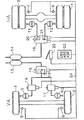
図1に、電子ブレーキシステム(EBS)及び統合されたABS及びASR機能を有する商用車のブレーキ装置のブロック回路図が示されている。車両は、前車軸VAにおける車輪1、2、及び二重タイヤとして構成された後車軸HAにおける車輪3、4を有する。すべての車輪の回転速度は、回転速度センサ5ないし8によって検出することができる。前車軸の車輪は、ブレーキシリンダ9、10によって、かつ後車軸の車輪は、ブレーキシリンダ11、12によって制動される。この場合、ブレーキ力を伝達するために圧縮空気が使われ、この圧縮空気は、貯蔵容器13、14内に蓄えられている。後車軸を管轄する容器14は、比例弁18を介して後車軸のためのブレーキシリンダ11、12に結合されている。前記の比例弁18は、電子装置ブロック23から到来する信号を介して電気的に制御することができる。後車軸のブレーキシリンダ11、12のブレーキ圧力PBは、圧力センサ20、21を介して検出することができ、かつ電子装置23に帰還通知される。このようにして所望のブレーキ圧力の正確な調整が可能である。このブレーキ圧力は、運転者によって操作されるブレーキ信号発生器22によってあらかじめ与えられ、このブレーキ信号発生器は、相応した電気出力信号を送出する。ブレーキ信号発生器22は、別のすべての電気部品のように、バスシステム24に接続されており、このバスシステムは、両方の方向に通信を伝達するために適しており、かつ例えばCANバスであることができる。部品は、同様に電子装置成分(インターフェース)を含んでいる。
【0015】
バスシステムの代わりに、通常のケーブル接続を設けてもよい。
【0016】
前車輪の動作ブレーキ圧力を調整するために、共通の比例弁15が設けられている。この比例弁は、圧力検出のために圧力センサ19を有する。したがってここでは両方の前車輪の圧力の個別の調節は、不可能である。
【0017】
比例弁15の出口は、ABS弁16、17を介して前車軸のブレーキシリンダ9、10に接続されている。前記のABS弁16、17は、オン−オフ弁として構成されており、かつ同様にバスシステム24から制御することができる。ここでもバスシステムの代わりに、通常のケーブル接続を設けてもよい。
【0018】
前記のブレーキ調整システムは、ハイブリッドシステムとも称する。このようなシステムは、調整弁15を、後車軸のための調整弁18よりも著しく簡単かつ望ましい価格で構成することができるという利点を有する。調整弁15は、ロック防止の役割を受持つ必要がないので、移動速度が、過剰に高い必要はない。ロック防止機能は、その代わりに前記のロック防止弁16、17によって受持たれ、これらロック防止弁は、きわめて迅速に反応することができる。このようにして、前車軸においてとくに重要なロック防止機能が、ここではとくに迅速に実行できることが達成される。その上前車軸に対してもブレーキシリンダ毎に高速調整弁(比例弁)を有する完全システムに対して、コストの節約が達成される。
【0019】
ハイブリッドシステムにおける所望のブレーキ圧力の調整は、前車軸に対して、動作制動の際又は開いたABS弁16、17の際にだけ可能である。それに対して、ABSシステムが動作している間に、前車軸のブレーキシリンダ9、10内に生じるブレーキ圧力は、もはや個々にはわからない。したがって具体的な差圧力ΔP又はヨーイングモーメントの調節は、このようなハイブリッドシステムの前車軸に対して不可能である。
【0020】
部分a)、b)、c)からなる図2の線図において、ABS調整されたブレーキに関して種々の速度経過、圧力経過及び調整信号が、時間に関して記入されている。
【0021】
図2aは、時間tに関して、ABS調整の間に一様に低下する車両速度VF、ロー−車輪VLの変化する車輪速度、及びロー−車輪にほぼ同期して一緒に制御されるハイ−車輪VHの速度を示している。
【0022】
図2bは、前車軸のハイ−及びロー−車輪のブレーキ圧力PBを時間tに関して示している。
【0023】
図2cは、前車軸のロー−車輪の所属の調整信号を示し、しかも車輪加速度+/−b及び車輪スリップλを時間tに関してい示している。
【0024】
時点t0に制動が始まる。ブレーキ圧力PBは、時点t1に−b調整信号が生じるまで、急勾配で上昇し、かつブレーキ圧力は、最高値Pmaxすなわち減圧調整開始圧力(調整圧力)から出発して、再び急速に低下する。低下は、−b信号が時点t2に再び減圧終了圧力値Pminに低下するとすぐに終了する。t1からt2までの期間tALは、電子装置23内において検出され、かつ記憶される。時点t1からハイ−車輪における圧力は、それ以上上昇するのではなく、時点t3まで一定に維持される。前記の時点t3は、+b調整信号の発生から生じる。この時点以後、ハイ−車輪のブレーキ圧力も低下し、しかも時点t4まで低下する。前記の時点t4は、時点t3と時間tAHの和から生じる。前記の時間tAHは、次に詳細に説明するように、電子装置23によって計算される。
【0025】
ここにおいて+b信号が再び低下する時点t5は、第2のABS調整サイクルのロー−車輪及びハイ−車輪における新たな圧力上昇とともに始まる。
【0026】
図2cによる調整信号λは、どの時間区間において調整されたロー−車輪がスリップ閾値を上回るかを示している。前記の例において、λ信号は、直接利用されるのではない。しかしこれは、ABS内において、とりわけいわゆる車輪の“緩慢なロック”を避けるために使われる。
【0027】
この時、本発明によれば、道路の状態及び車両の積荷に整合した最適なヨーイングモーメントは、次のようにして達成される。すなわち前車軸VAの一緒に制御されるハイ−車輪のブレーキシリンダ9又は10の空気逃し時間tAHは、後車軸(駆動車軸)HAのハイ−及びロー−車輪のブレーキ圧力PBに、又は後車軸のハイ−車輪及びロー−車輪及び前車軸VAのロー−車輪のブレーキ圧力に依存している。前記のブレーキ圧力PBとして、目的に合うように、いわゆる調整圧力(図2におけるPmax)が利用される。調整圧力は、一般に圧力低下段階が続くABS調整サイクルの間のブレーキシリンダ内におけるそれぞれ最高の圧力である。ブレーキ圧力は、ブレーキ力に直接比例している。それにより調整圧力が、ちょうど支配的な最大ブレーキ力に、したがってタイヤと道路の間のちょうど利用できる力結合潜在能力にも直接比例していることが明らかである。これは、増加する摩擦値(又は道路の品質)及び増加するタイヤ負荷とともに高まるので、調整圧力は、道路品質及び車両の積荷に関する情報を含んでいる。一般に前記の空気逃し時間tAHを計算するために、後車軸の調整圧力が利用される。なぜなら(比較的高価な)圧力センサによって後車輪のブレーキマスタシリンダにおけるブレーキ圧力を検出することで、一般に十分であるからである。
【0028】
本発明の第1の変形によれば、前記の空気逃し時間は、電子装置23によって次の式にしたがって計算され:
【0029】
【数1】
【0030】
その際、
tAH:一緒に制御される前車輪(ハイ−車輪)の空気逃し時間
tAL:調整される前車輪(ロー−車輪)の空気逃し時間
【0031】
【数2】
【0032】
K1、K2:定数
PmaxH:ハイ−側の駆動車輪の調整圧力
PmaxL:ロー−側の駆動車輪の調整圧力
である。
【0033】
時間tALに関してそれぞれ得られた値は、電子装置23によって検出される。
【0034】
その際、定数K1及びK2に対して意味のある値として:
0.4≦K1≦0.9
及び
0≦K2≦0.07/バール
が得られた。
【0035】
A1に対する値は、実際に1より大きくないので、空気逃し時間tAHに対して常に空気逃し時間tALより小さな値が得られる。それにより差圧力又はヨーイングモーメントの最大値の徐々に行なわれる上昇及び制限が生じる。
【0036】
0.0と1.0の間の値、なるべく0.2と0.8の間の値に値A1を制限することは、目的に合っている。
【0037】
前記の空気逃し時間tAHを次式にしたがって計算することも可能である:
【0038】
【数3】
【0039】
その際、
【0040】
【数4】
。
【0041】
これにより摩擦値の相違が大きい際に、車両の積荷が、とくに良好に考慮される。
【0042】
さらに空気逃し時間tAHを次式にしたがって計算することが可能である:
【0043】
【数5】
【0044】
その際、
【0045】
【数6】
。
【0046】
これにより絶対的な圧力の大きさの影響が減少され、すなわち積荷及び車輪ブレーキにおける比、ブレーキ力/ブレーキ圧力の影響が減少される。
【0047】
さらに空気逃し時間tAHを次式にしたがって計算することが可能である:
【0048】
【数7】
【0049】
その際、
【0050】
【数8】
。
【0051】
その際、K8、K9、K10はここでも定数であり、かつPmaxLVAは、ロー−側の前車輪の調整圧力である。
【0052】
この計算様式は、ロー−側の摩擦値をさらに大幅に考慮するという利点を有する。後車軸の調節圧力は、大きな摩擦値においても積荷を積んでいない車両においてきわめて小さい。それにより両側において大きな摩擦値において車両が安定に制動するといえども、大きな摩擦値における積荷のない車両の際、両方の車両側においてVAにおける小さな差圧力だけ、及び小さな許容ヨーイングモーメントだけしか生じない。ロー−前車輪の調整圧力を含めることによって、この効果は減少することができ、したがってさらに大きなブレーキ力が利用でき、かつブレーキ行程が短縮できる。
【0053】
駆動車軸の前記の調整圧力PmaxH及びPmaxLの代わりに、駆動車軸の車輪の調整された圧力の平均経過も利用することができる。これは、目的に合うように次式にしたがって計算され:
【0054】
【数9】
、
【0055】
その際、Pminは、駆動車軸のそれぞれの車輪のいわゆる保持圧力すなわち減圧終了圧力値である(図2b参照)。
【0056】
さらに調整圧力PmaxH、PmaxLの代わりに、ブレーキ圧力の時間に関して平均化された値も利用することができる。これは、電子装置23内における強力なフィルタ処理によって計算することができる。
【0057】
駆動される後車軸の他に、リフト可能な車輪を有する別の後車軸(リフト車軸)が存在する車両も利用される。この構造様式において、前記のリフト車軸を降下した場合、明らかに駆動される車軸の車輪負荷が減少する。駆動車軸の車輪における車輪負荷の減少により、この時ここでも調整圧力は減少する。なぜなら駆動車軸の車輪の最大限伝達できるブレーキ力は、小さくなるからである。この場合、時間tAHを計算する前記の方法によれば、舵取り車軸の車輪において得られるブレーキ圧力差は、リフト車軸の降下によって変化するようになり、しかも一層小さなヨーイングモーメントの方向に変化するようになる。
【0058】
しかしながらこの結果は、望ましいわけではない。なぜならμスプリット摩擦値において降下したリフト車軸を有する車両は、経験によればかつ理論的に証明可能にも一層安定に制動するからである。したがってこの場合、車両が支配不可能になることなく、舵取り車軸の車輪における一層大きなブレーキ圧力差ΔPが可能である。
【0059】
目的に合った方法によってリフト車軸位置を認識し(例えば適当な検出を介して)、かつリフト車軸の位置を電子装置23のEBS又はABSに伝達することによって、この問題に対処することができる。それからこの場合、前車軸VAの一緒に制御される車輪の空気逃し時間tAHは、リフト車軸を降下した際に前記の一層安定な制動を利用するため、したがってブレーキ行程を短縮するために、相応して短縮される。このことは、次のようにして行なうことができる。すなわち次の式に:
【0060】
【数1】
【0061】
次のような項A1を算入する:
【0062】
【数10】
。
【0063】
その際、追加的な係数K11は、1より大きいので、A1に対する値は小さくなる。それによりここでもハイ−車輪の空気逃し時間tAHの短縮が生じ、それにより差圧力ΔP又は許容ヨーイングモーメントは上昇する。
【0064】
特別の場合に、前車軸のブレーキシリンダのブレーキ圧力情報も存在するならば、前記の式に:
【0065】
【数7】
【0066】
を挿入してもよい。
【0067】
【数11】
【0068】
定数K11は、目的に合うように次の商から形成することができる:
【0069】
K11=(車輪負荷、駆動車軸+車輪負荷、リフト車軸)/車輪負荷、駆動車軸
【0070】
この商は、ほとんどの場合車両データから大雑把に検出することができる。なぜならリフト車軸を降下した際の固定の車軸負荷状態は、ほとんどの場合構造的に提示されているからである。定数K11に対して値範囲としてほぼ:
1.3≦K11≦2
を示すことができる。定数K11に対する1.5の値が、FG範囲におけるほとんどの車両タイプのために利用することができる。
【0071】
車軸負荷に対して、邸動車軸及びリフト車軸の軸負荷の適当な検出によって検出することができる値を利用することも、場合によっては可能である。これら値は、ABS又はEBSの電子装置に引渡される。それにより前記の商は、一層正確に計算することもできる。このことは、リフト車軸を降下した際の車軸負荷状態が一定ではなく、例えばトラクション制御を実現するために選択可能である車両において、とくに意味がある。
【図面の簡単な説明】
【図1】統合されたアンチロックシステム(ABS)を有する電子ブレーキシステム(EBS)の概略的なブロック回路図である。
【図2】舵取り車軸(前車軸VA)のロー−車輪及びハイ−車輪の車輪速度(V)、ブレーキ圧力(PB)及び調整信号(+/−b、λ)を調整される制動の間に時間(t)に関して記入した線図である。
【符号の説明】
1 車輪
2 車輪
3 車輪
4 車輪
5 回転速度センサ
6 回転速度センサ
7 回転速度センサ
8 回転速度センサ
9 ブレーキシリンダ
10 ブレーキシリンダ
11 ブレーキシリンダ
12 ブレーキシリンダ
HA 後車軸
VA 前車軸
PB ブレーキ圧力
Pmax 調整圧力
Pm 平均圧力
tAH 空気逃し時間[0001]
BACKGROUND OF THE INVENTION
The present invention is a method for attenuating a yawing moment in a vehicle having an anti-lock system when braking the vehicle on a road having different friction coefficients on the left and right, and at least information on the brake pressure of the wheels on the rear axle is used. that on those.
[0002]
[Prior art]
When braking a vehicle on a road with a different friction value on the side, a yawing moment is generated as is well known, and this yawing moment tries to turn the vehicle in the direction of the road with the higher friction value. To do. The driver must deal with this effect by reverse steering. However, this can be a problem for unskilled drivers, particularly when the yawing moment suddenly occurs or is particularly severe due to undesired conditions. Such conditions include, for example, the vehicle's short wheelbase, large treads, large positive steering roll radii, slight loads, especially very different road conditions such as concrete and ice, and for example adjusting anti-lock systems (ABS). ) May be a particularly powerful brake operation, such as braking.
[0003]
Therefore, especially in vehicles equipped with ABS, the yawing moment that is generated during regulated braking on roads with different lateral surfaces (μ-split) is configured to rise slowly, and thus the stability of the vehicle It is already well known to increase the driving force and reduce the burden on the driver. This is done in particular by special measures in the electronic device of the ABS (German Patent Application Publication No. 2855326). Wheels traveling on the smooth road side (low-wheels) are first adjusted by ABS, while wheels traveling on the gripping side (high-wheels) are controlled together by a low-wheel brake pressure adjustment signal. .
[0004]
In so doing, the differential pressure or yawing moment increases until the high-wheel also begins to adjust.
[0005]
Vehicles with so-called electronic brake systems (EBS) are also known, in which the electrical target value from the brake pressure signal generator can be adjusted (actual value) as the brake pressure in the brake cylinder (Germany) Republic Patent Application Publication No. 4406235). These brake systems are also usually equipped with ABS. Here, since a pressure sensor is used to detect the brake pressure, in a pneumatic brake system with ABS, the brake pressure difference between the low-wheel on the smooth road side and the high-wheel on the gripping road side. It can be easily deduced to limit (ΔP) to a constant value and thus achieve yawing moment damping.
[0006]
Furthermore, conventional ABS is known (German Patent Application 2460309), and this ABS is equipped with a brake pressure sensor. In doing so, the high-wheels can be controlled together in terms of pressure by the ABS-adjusting low-wheels, or the high-wheel pressures are also averaged to meet the purpose for the low-wheel pressures. While maintaining the brake pressure difference (ΔP), it can be maintained at a constant value.
[0007]
Finally, according to DE 28 51 107, the brake pressure at the high-wheels is still kept constant during the low-wheel air relief until the low-wheel slip signal (λ) drops. It is known to limit the yawing moment that occurs on the μ-split travel path in ABS. Following this, the high-wheels are also evacuated and for a period of time that is a predetermined fraction of their pressure maintenance time. This also achieves an impact-free yawing moment to a considerable extent that rises slowly.
[0008]
It is disadvantageous in the known device that the damping of the obtained yawing moment is not tuned to the respective road conditions on both road sides and thus to the high side and to the respective vehicles. The maximum high-wheel brake pressure is dependent on the low-wheel brake pressure course, which is determined by the low-wheel friction force, and is limited in the early stages, by a time-delayed configuration. The high-wheel brake pressure, which is tolerated to the maximum for vehicle behavior that can still be controlled, is not always fully utilized. Thus, it may happen that the braking stroke is provided by too much under-braking of the high-wheels in changing road surfaces.
[0009]
In some cases, the known constant configuration of the brake pressure difference (ΔP) is too large for dangerous vehicles (semi-trailers with no load), so that these can only be controlled by the driver with difficulty or not at all. Can also happen.
[0010]
[Problems to be solved by the invention]
The object of the present invention is to attenuate yawing moments in vehicles with an antilock system, which on the one hand reduces the driver's burden due to excessive reverse steering and on the other hand reduces the braking stroke of the vehicle relative to known systems. It is to provide a method.
[0011]
[Means for Solving the Problems]
This problem is solved by the present invention as follows. That front axle low - high is controlled with the wheel - wheel and low - - air escape time of the wheel brake cylinders, the car axis high after being driven to the wheel brake pressure, dependent or rear axle High- wheel and low-wheel brake pressure and front axle low-wheel brake pressure. The dependent claims of the claims include specific embodiments for the purpose.
[0012]
By applying the method according to the invention, yawing moment damping that is automatically adapted to changing road conditions and vehicle types or loads and thus contributes to shortening the total braking stroke is possible. At that time, the control ability of the vehicle is maintained. By including the adjustment pressure in the detection of the allowed pressure difference, the road quality and the vehicle load are taken into account in a special way.
[0013]
DETAILED DESCRIPTION OF THE INVENTION
Next, the present invention will be described in detail with reference to the drawings.
[0014]
FIG. 1 shows a block circuit diagram of an electronic brake system (EBS) and a commercial vehicle brake system having an integrated ABS and ASR function. The vehicle has
[0015]
A normal cable connection may be provided instead of the bus system.
[0016]
A common
[0017]
The outlet of the
[0018]
The brake adjustment system is also referred to as a hybrid system. Such a system has the advantage that the regulating
[0019]
Adjustment of the desired brake pressure in the hybrid system is only possible with respect to the front axle during operation braking or when the
[0020]
In the diagram of FIG. 2 consisting of parts a), b), c), various speed courses, pressure courses and regulation signals are entered with respect to time for the ABS adjusted brake.
[0021]
FIG. 2a shows that, with respect to time t, the vehicle speed VF that decreases uniformly during ABS adjustment, the changing wheel speed of the low-wheel VL, and the high-wheel VH that are controlled together almost synchronously with the low-wheel. Shows the speed.
[0022]
FIG. 2b shows the front axle high- and low-wheel brake pressure PB with respect to time t.
[0023]
FIG. 2c shows the adjustment signal for the low-wheel belonging to the front axle and also the wheel acceleration +/− b and the wheel slip λ with respect to time t.
[0024]
Braking starts at time t0. The brake pressure PB rises steeply until the -b adjustment signal occurs at time t1, and the brake pressure starts again from the maximum value Pmax, that is, the pressure reduction adjustment start pressure (adjustment pressure), and then rapidly decreases again. The decrease ends as soon as the -b signal decreases again to the pressure reduction end pressure value Pmin at time t2. The period tAL from t1 to t2 is detected and stored in the
[0025]
Here, the time t5 when the + b signal drops again begins with a new pressure rise on the low-wheel and high-wheel of the second ABS adjustment cycle.
[0026]
The adjustment signal λ according to FIG. 2c indicates in which time interval the adjusted low-wheel exceeds the slip threshold. In the above example, the λ signal is not used directly. However, this is used in the ABS, in particular to avoid so-called “slow locking” of the wheels.
[0027]
At this time, according to the present invention, the optimum yawing moment that matches the road conditions and the vehicle load is achieved as follows. That is, the air escape time tAH of the high-
[0028]
According to a first variant of the invention, the air escape time is calculated by the
[0029]
[Expression 1]
[0030]
that time,
tAH: Air escape time of front wheel (high-wheel) controlled together tAL: Air escape time of front wheel (low-wheel) adjusted together
[Expression 2]
[0032]
K1, K2: Constant PmaxH: Adjustment pressure of the high-side drive wheel PmaxL: Adjustment pressure of the low-side drive wheel.
[0033]
The value obtained for each time tAL is detected by the
[0034]
In that case, the meaningful values for the constants K1 and K2 are:
0.4 ≦ K1 ≦ 0.9
And 0 ≦ K2 ≦ 0.07 / bar.
[0035]
Since the value for A1 is not actually greater than 1, a value smaller than the air escape time tAL is always obtained for the air escape time tAH. This causes a gradual increase and limitation of the maximum value of the differential pressure or yawing moment.
[0036]
Limiting the value A1 to a value between 0.0 and 1.0, preferably between 0.2 and 0.8, suits the purpose.
[0037]
It is also possible to calculate the air escape time tAH according to the following formula:
[0038]
[Equation 3]
[0039]
that time,
[0040]
[Expression 4]
.
[0041]
Thus, when the difference in friction value is large, the load of the vehicle is considered particularly well.
[0042]
Furthermore, the air escape time tAH can be calculated according to the following formula:
[0043]
[Equation 5]
[0044]
that time,
[0045]
[Formula 6]
.
[0046]
This reduces the effect of absolute pressure magnitude, i.e. the ratio in load and wheel brakes, the effect of brake force / brake pressure.
[0047]
Furthermore, the air escape time tAH can be calculated according to the following formula:
[0048]
[Expression 7]
[0049]
that time,
[0050]
[Equation 8]
.
[0051]
In this case, K8, K9 and K10 are also constants here, and PmaxLVA is the adjustment pressure of the front wheel on the low side.
[0052]
This mode of calculation has the advantage that the low-side friction value is taken into account more significantly. The adjusting pressure of the rear axle is very small in vehicles that are not loaded even at large friction values. Even if this results in a stable braking of the vehicle at large friction values on both sides, only a small differential pressure at VA and a small allowable yawing moment will occur on both vehicle sides when there is no load at large friction values. By including the regulation pressure of the low-front wheel, this effect can be reduced, so that a greater braking force can be used and the braking stroke can be shortened.
[0053]
Instead of the adjustment pressures PmaxH and PmaxL of the drive axle, the average course of the adjusted pressure of the wheels of the drive axle can also be used. This is calculated according to the following formula to suit the purpose:
[0054]
[Equation 9]
,
[0055]
In this case, Pmin is a so-called holding pressure of each wheel of the drive axle, that is, a pressure reduction end pressure value (see FIG. 2b).
[0056]
Further, instead of the adjustment pressures PmaxH and PmaxL, values averaged with respect to the time of the brake pressure can also be used. This can be calculated by powerful filtering within the
[0057]
In addition to the driven rear axle, a vehicle having another rear axle (lift axle) having liftable wheels is also used. In this construction mode, when the lift axle is lowered, the wheel load on the clearly driven axle is reduced. Due to the reduction of the wheel load on the wheels of the drive axle, the adjustment pressure again decreases at this time. This is because the braking force that can be transmitted to the maximum of the wheels of the drive axle is reduced. In this case, according to the above method for calculating the time tAH, the brake pressure difference obtained at the wheel of the steering axle will change with the descent of the lift axle, and in the direction of the smaller yawing moment. Become.
[0058]
However, this result is not desirable. This is because a vehicle having a lift axle lowered at a μ-split friction value will brake more stably by experience and theoretically proveable. Therefore, in this case, a greater brake pressure difference ΔP at the steering axle wheel is possible without the vehicle becoming incapable of control.
[0059]
This problem can be addressed by recognizing the position of the lift axle in a way that suits the purpose (eg, via suitable detection) and communicating the position of the lift axle to the EBS or ABS of the
[0060]
[Expression 1]
[0061]
Include the following term A1:
[0062]
[Expression 10]
.
[0063]
At this time, the additional coefficient K11 is larger than 1, so the value for A1 becomes smaller. This again reduces the high-wheel air escape time tAH, thereby increasing the differential pressure ΔP or the allowable yawing moment.
[0064]
In the special case, if the brake pressure information of the front axle brake cylinder is also present, the above formula:
[0065]
[Expression 7]
[0066]
May be inserted.
[0067]
[Expression 11]
[0068]
The constant K11 can be formed from the following quotients to suit the purpose:
[0069]
K11 = (wheel load, drive axle + wheel load, lift axle) / wheel load, drive axle
In most cases, this quotient can be roughly detected from the vehicle data. This is because the fixed axle load state when the lift axle is lowered is structurally presented in most cases. As a value range for the constant K11:
1.3 ≦ K11 ≦ 2
Can be shown. A value of 1.5 for the constant K11 can be used for most vehicle types in the FG range.
[0071]
It is also possible in some cases to use a value that can be detected by appropriate detection of the axle load of the maneuvering axle and the lift axle for the axle load. These values are delivered to an ABS or EBS electronic device. Thereby, the quotient can also be calculated more accurately. This is particularly significant in vehicles where the axle load state when the lift axle is lowered is not constant and can be selected, for example, to achieve traction control.
[Brief description of the drawings]
FIG. 1 is a schematic block circuit diagram of an electronic brake system (EBS) having an integrated anti-lock system (ABS).
FIG. 2 shows the steering wheel (front axle VA) low-wheel and high-wheel wheel speed (V), brake pressure (PB) and adjustment signals (+/− b, λ) during the adjusted braking. It is the diagram filled in regarding time (t).
[Explanation of symbols]
DESCRIPTION OF
Claims (13)
tAH=A1×tAL
その際、
tAH:前車軸のロー−車輪と一緒に制御されるハイ−車輪の空気逃し時間
tAL:前車軸の調整されるロー−車輪の空気逃し時間
A1=K1−K2×(PmaxH+PmaxL)
K1、K2:定数
PmaxH:ハイ−側の後車輪の減圧調整開始圧力
PmaxL:ロー−側の後車輪の減圧調整開始圧力
であることを特徴とする、請求項2記載の方法。The air escape time (t AH ) of the high-wheel brake cylinder (9 or 10) controlled along with the front-axle (VA) low-wheel is calculated according to the following equation:
t AH = A 1 × t AL
that time,
t AH: front axle row - are controlled with the wheel Ruha Lee - car wheel air escape time t AL: front axle of the adjusted Carlo sitting - car wheel air escape time A 1 = K 1 -K 2 × (Pmax H + Pmax L )
K 1, K 2: constants Pmax H: High - wheels vacuum controller starting pressure Pmax L after side: Low - characterized in that it is a vacuum controller start pressure of the wheel after the side, The method of claim 2 wherein.
tAH=A2×tAL
その際、
tAH:前車軸のロー−車輪と一緒に制御されるハイ−車輪の空気逃し時間
tAL:前車軸の調整されるロー−車輪の空気逃し時間
A2=K3−K4×(PmaxH−PmaxL)
K3、K4:定数
PmaxH:ハイ−側の後車輪の減圧調整開始圧力
PmaxL:ロー−側の後車輪の減圧調整開始圧力
であることを特徴とする、請求項1ないし2の1つに記載の方法。The air escape time (t AH ) of the high-wheel brake cylinder (9 or 10) controlled with the front-axle (VA) low-wheel is calculated according to the following formula:
t AH = A 2 × t AL
that time,
t AH: front axle row - are controlled with the wheel Ruha Lee - car wheel air escape time t AL: front axle of the adjusted Carlo sitting - car wheel air escape time A 2 = K 3 -K 4 × (Pmax H −Pmax L )
K 3, K 4: constants Pmax H: High - wheel reduced pressure adjustment start pressure after side Pmax L: Low - characterized in that it is a vacuum controller start pressure after the side wheels, according to claim 1 or 2 1 The method described in one.
tAH=A3×tAL
その際、
tAH:前車軸のロー−車輪と一緒に制御されるハイ−車輪の空気逃し時間
tAL:前車軸の調整されるロー−車輪の空気逃し時間
A3=K6−K7×(PmaxH/PmaxL)
K6、K7:定数
PmaxH:ハイ−側の後車輪の減圧調整開始圧力
PmaxL:ロー−側の後車輪の減圧調整開始圧力
であることを特徴とする、請求項1ないし2の1つに記載の方法。The air escape time (t AH ) of the high-wheel brake cylinder (9 or 10) controlled with the front-axle (VA) low-wheel is calculated according to the following formula:
t AH = A 3 × t AL
that time,
t AH: front axle row - are controlled with the wheel Ruha Lee - car wheel air escape time t AL: front axle of the adjusted Carlo sitting - car wheel air escape time A 3 = K 6 -K 7 × (Pmax H / Pmax L )
K6, K 7: constants Pmax H: High - wheel reduced pressure adjustment start pressure after side Pmax L: Low - characterized in that it is a vacuum controller start pressure after the side wheels, one of claims 1 to 2 The method described in 1.
tAH=A4×tAL
その際、
tAH:前車軸のロー−車輪と一緒に制御されるハイ−車輪の空気逃し時間
tAL:前車軸の調整されるロー−車輪の空気逃し時間
A4=K8−K9×(PmaxH+PmaxL+K10×PmaxLVA)
K8、K9、K10:定数
PmaxH:ハイ−側の後車輪の減圧調整開始圧力
PmaxL:ロー−側の後車輪の減圧調整開始圧力
PmaxLVA:ロー−側の前車輪の減圧調整開始圧力
であることを特徴とする、請求項1ないし2の1つに記載の方法。In but also information about the brake pressure (PB) of the wheels of the front axle (VA) is used, the front axle row (VA) - air wheel brake cylinder (9 or 10) - high to be controlled with a wheel The miss time (t AH ) is calculated according to the following formula:
t AH = A 4 × t AL
that time,
t AH: front axle row - are controlled with the wheel Ruha Lee - car wheel air escape time t AL: front axle of the adjusted Carlo sitting - car wheel air escape time A 4 = K 8 -K 9 × (Pmax H + Pmax L + K 10 × Pmax LVA )
K 8 , K 9 , K 10 : Constant Pmax H : High-side rear wheel decompression adjustment start pressure Pmax L : Low-side rear wheel decompression adjustment start pressure Pmax LVA : Low-side front wheel decompression adjustment 3. A method according to claim 1, characterized in that it is a starting pressure.
その際、
Pm=(Pmax+Pmin)/2
その際、
Pmin=保持圧力すなわち減圧終了圧力値
であることを特徴とする、請求項1ないし6の1つに記載の方法。Instead of the pressure reduction adjustment starting pressure (Pmax), the average pressure Pm is used,
that time,
Pm = (Pmax + Pmin) / 2
that time,
Method according to one of claims 1 to 6, characterized in that Pmin = holding pressure, i.e. the pressure reduction end pressure value .
A1=K1−K2×K11×(PmaxH+PmaxL)
その際、K11≧1
であることを特徴とする、請求項3記載の方法。In a method for a vehicle having a lift axle, recognizing a lift axle lowered by a suitable method , the term A1 is calculated according to the following equation:
A 1 = K 1 −K 2 × K 11 × (Pmax H + Pmax L )
At that time, K11 ≧ 1
The method according to claim 3, wherein:
A4=K8−K9×〔K12×(PmaxH+PmaxL)+K10×PmaxLVA〕
ことを特徴とする、請求項6記載の方法。In a method for a vehicle having a lift axle, recognizing a lift axle lowered by an appropriate method , the term A4 is calculated according to the following formula:
A 4 = K 8 -K 9 × [K 12 × (Pmax H + Pmax L) + K10 × Pmax LVA ]
The method according to claim 6, wherein:
K11=(後車軸の車輪負荷+リフト車軸の車輪負荷)/後車軸の車輪負荷
ことを特徴とする、請求項10ないし12の1つに記載の方法。Constant K11, wherein the following K11 = (wheel load of the wheel load + lift axle of the rear axle) / rear axle wheel load being formed by the equation, according to one of claims 10 to 12 the method of.
Applications Claiming Priority (2)
| Application Number | Priority Date | Filing Date | Title |
|---|---|---|---|
| DE19647997A DE19647997A1 (en) | 1996-11-20 | 1996-11-20 | Method for reducing yaw moment in a vehicle with an anti-lock braking system |
| DE19647997.5 | 1996-11-20 |
Publications (2)
| Publication Number | Publication Date |
|---|---|
| JPH10152034A JPH10152034A (en) | 1998-06-09 |
| JP4148302B2 true JP4148302B2 (en) | 2008-09-10 |
Family
ID=7812223
Family Applications (1)
| Application Number | Title | Priority Date | Filing Date |
|---|---|---|---|
| JP34988997A Expired - Lifetime JP4148302B2 (en) | 1996-11-20 | 1997-11-14 | Method for damping yawing moment in vehicles with anti-lock system |
Country Status (4)
| Country | Link |
|---|---|
| US (1) | US6000765A (en) |
| EP (1) | EP0844155B1 (en) |
| JP (1) | JP4148302B2 (en) |
| DE (2) | DE19647997A1 (en) |
Families Citing this family (20)
| Publication number | Priority date | Publication date | Assignee | Title |
|---|---|---|---|---|
| SE9701443L (en) * | 1997-04-18 | 1998-02-23 | Scania Cv Ab | Device for a vehicle |
| DE19732998A1 (en) | 1997-07-31 | 1999-02-04 | Itt Mfg Enterprises Inc | Method and device for detecting a braking situation |
| US6663113B2 (en) | 1998-10-09 | 2003-12-16 | Robert Bosch Gmbh | System and method for reducing stopping distance and improving traction in motor vehicles |
| DE10053608B4 (en) * | 2000-10-28 | 2010-01-28 | Robert Bosch Gmbh | Traction control device and method for controlling the slip of a wheel |
| DE10156958B4 (en) * | 2000-12-06 | 2011-02-03 | Continental Teves Ag & Co. Ohg | Method and device for improving the control behavior of an anti-lock brake system |
| DE10232792A1 (en) | 2002-07-19 | 2004-02-12 | Wabco Gmbh & Co. Ohg | Braking method for a vehicle |
| US20040201272A1 (en) * | 2003-04-08 | 2004-10-14 | Delphi Technologies Inc. | ABS yaw control with yaw rate sensor |
| DE502006003630D1 (en) * | 2005-09-14 | 2009-06-10 | Continental Teves Ag & Co Ohg | METHOD FOR DETERMINING AN INHOMOGENIC RAILWAY |
| FR2894211B1 (en) * | 2005-12-06 | 2008-02-08 | Lohr Ind | BRAKE SYSTEM WITH TWO-STAGE ELECTRO-PNEUMATIC CONTROL FOR A MULTI-AXLE ROAD VEHICLE. |
| JP5421222B2 (en) | 2010-11-08 | 2014-02-19 | トヨタ自動車株式会社 | Braking force control device |
| DE102014216265A1 (en) * | 2014-08-15 | 2016-02-18 | Continental Teves Ag & Co. Ohg | Method for adapting the control strategy of a slip control system of a vehicle in a μ-split situation |
| DE102014017683A1 (en) | 2014-11-28 | 2016-06-02 | Wabco Gmbh | Method for controlling a pneumatic brake system and such pneumatic brake system for a vehicle |
| US10675936B2 (en) | 2014-12-16 | 2020-06-09 | Atv8 Llc | System and method for vehicle stabilization |
| WO2016100529A1 (en) | 2014-12-16 | 2016-06-23 | Aktv8 LLC | Electronically controlled vehicle suspension system and method of manufacture |
| US10160278B2 (en) | 2014-12-16 | 2018-12-25 | Aktv8 LLC | System and method for vehicle stabilization |
| US10870325B2 (en) | 2014-12-16 | 2020-12-22 | Aktv8 LLC | System and method for vehicle stabilization |
| US9937748B2 (en) | 2015-04-09 | 2018-04-10 | Patrick Norton | Bead lock systems and methods |
| DE102015016721A1 (en) | 2015-12-22 | 2017-06-22 | Wabco Gmbh | A method of regulating vehicle actual deceleration in a vehicle having an ABS braking system |
| ES2926640T3 (en) | 2016-09-06 | 2022-10-27 | Aktv8 LLC | Tire Management System and Procedures |
| KR20220057674A (en) * | 2020-10-29 | 2022-05-09 | 주식회사 만도 | Apparatus and method for controlling vehicle and, vehicle system |
Family Cites Families (13)
| Publication number | Priority date | Publication date | Assignee | Title |
|---|---|---|---|---|
| DE2460309A1 (en) * | 1974-12-20 | 1976-06-24 | Wabco Westinghouse Gmbh | ANTI-SKID CONTROL SYSTEM FOR PRESSURE-ACTUATED VEHICLE BRAKES |
| DE2851107C2 (en) * | 1978-11-25 | 1990-03-08 | Wabco Westinghouse Fahrzeugbremsen GmbH, 3000 Hannover | Circuit arrangement for improving the driving stability of vehicles equipped with anti-lock braking systems |
| DE2855326A1 (en) * | 1978-12-21 | 1980-07-17 | Wabco Fahrzeugbremsen Gmbh | CIRCUIT ARRANGEMENT FOR IMPROVING DRIVING STABILITY IN THE BRAKE CASE OF VEHICLES WITH BLOCK-PROTECTED VEHICLE BRAKE SYSTEMS |
| DE3501381A1 (en) * | 1985-01-17 | 1986-07-17 | Robert Bosch Gmbh, 7000 Stuttgart | ANTI-BLOCKING BRAKE SYSTEM |
| JPH0775974B2 (en) * | 1986-10-16 | 1995-08-16 | 日本エ−ビ−エス株式会社 | Hydraulic control device for anti-skidding device |
| GB8711303D0 (en) * | 1987-05-13 | 1987-06-17 | Lucas Ind Plc | Anti-skid braking systems |
| DE3903585A1 (en) * | 1989-02-07 | 1990-08-09 | Knorr Bremse Ag | ANTI-BLOCKED BRAKE SYSTEM WITH Yaw Torque Limitation |
| DE4033767A1 (en) * | 1990-10-24 | 1992-04-30 | Bosch Gmbh Robert | ELECTRO-PNEUMATIC BRAKE SYSTEM |
| DE4114734A1 (en) * | 1991-05-06 | 1992-11-12 | Teves Gmbh Alfred | CIRCUIT ARRANGEMENT FOR A BRAKE SYSTEM WITH ELECTRONIC BLOCKING PROTECTION CONTROL |
| US5315518A (en) * | 1991-06-10 | 1994-05-24 | General Motors Corporation | Method and apparatus for initializing antilock brake control on split coefficient surface |
| US5275474A (en) * | 1991-10-04 | 1994-01-04 | General Motors Corporation | Vehicle wheel slip control on split coefficient surface |
| DE4406235A1 (en) * | 1994-02-25 | 1995-08-31 | Wabco Vermoegensverwaltung | Pressure control device |
| DE4441624A1 (en) * | 1994-11-23 | 1996-05-30 | Teves Gmbh Alfred | Circuit arrangement for a brake system with anti-lock control |
-
1996
- 1996-11-20 DE DE19647997A patent/DE19647997A1/en not_active Withdrawn
-
1997
- 1997-09-19 EP EP97116337A patent/EP0844155B1/en not_active Expired - Lifetime
- 1997-09-19 DE DE59707097T patent/DE59707097D1/en not_active Expired - Lifetime
- 1997-11-14 JP JP34988997A patent/JP4148302B2/en not_active Expired - Lifetime
- 1997-11-17 US US08/968,815 patent/US6000765A/en not_active Expired - Lifetime
Also Published As
| Publication number | Publication date |
|---|---|
| EP0844155B1 (en) | 2002-04-24 |
| EP0844155A3 (en) | 1999-07-21 |
| DE59707097D1 (en) | 2002-05-29 |
| US6000765A (en) | 1999-12-14 |
| DE19647997A1 (en) | 1998-05-28 |
| JPH10152034A (en) | 1998-06-09 |
| EP0844155A2 (en) | 1998-05-27 |
Similar Documents
| Publication | Publication Date | Title |
|---|---|---|
| JP4148302B2 (en) | Method for damping yawing moment in vehicles with anti-lock system | |
| US8442737B2 (en) | Method for operating a vehicle brake system and vehicle brake system | |
| US5624164A (en) | Braking force distribution control system | |
| EP1721796B1 (en) | Pressure boost for vehicle rear brake circuits | |
| JP5126427B1 (en) | Vehicle braking force distribution control device | |
| KR20010015907A (en) | Method and device for stabilising a motor vehicle in order to prevent it from rolling over | |
| CA2486396A1 (en) | Antilock braking system based roll over prevention | |
| JPH0712813B2 (en) | Slip control type brake system | |
| JPH0647369B2 (en) | Breaker for automobile | |
| US6923514B1 (en) | Electronic brake control system | |
| JP4151039B2 (en) | Method of damping yaw moment in anti-lock device | |
| JP3350042B2 (en) | Pressure medium operated braking device for multi-axle vehicles | |
| US5842755A (en) | Braking force control system in vehicle | |
| US4632467A (en) | Brake system with brake slip control | |
| GB2317930A (en) | Vehicle with automatic braking effort control on downhill gradients | |
| US10625719B2 (en) | Method for adjusting brake pressures on pneumatically actuated wheel brakes of a vehicle, brake system for carrying out the method, and vehicle | |
| JP3529643B2 (en) | Braking method and brake device | |
| JP2004504987A (en) | Stabilizer for vehicles with compressed air actuated brake device | |
| JPH0911871A (en) | Brake force distribution control method of vehicle | |
| CN108025709B (en) | Motor vehicle traction control system and method | |
| JP2500857B2 (en) | Anti-skidding control device | |
| JP3205684B2 (en) | Vehicle braking force distribution control method | |
| US4896924A (en) | Antiskid control device | |
| JPH0542864A (en) | Anti-skid controller | |
| JP4953507B2 (en) | How to maintain engine braking |
Legal Events
| Date | Code | Title | Description |
|---|---|---|---|
| A621 | Written request for application examination |
Free format text: JAPANESE INTERMEDIATE CODE: A621 Effective date: 20041029 |
|
| A131 | Notification of reasons for refusal |
Free format text: JAPANESE INTERMEDIATE CODE: A131 Effective date: 20080115 |
|
| A521 | Written amendment |
Free format text: JAPANESE INTERMEDIATE CODE: A523 Effective date: 20080403 |
|
| TRDD | Decision of grant or rejection written | ||
| A01 | Written decision to grant a patent or to grant a registration (utility model) |
Free format text: JAPANESE INTERMEDIATE CODE: A01 Effective date: 20080610 |
|
| A01 | Written decision to grant a patent or to grant a registration (utility model) |
Free format text: JAPANESE INTERMEDIATE CODE: A01 |
|
| A61 | First payment of annual fees (during grant procedure) |
Free format text: JAPANESE INTERMEDIATE CODE: A61 Effective date: 20080617 |
|
| FPAY | Renewal fee payment (event date is renewal date of database) |
Free format text: PAYMENT UNTIL: 20110704 Year of fee payment: 3 |
|
| R150 | Certificate of patent or registration of utility model |
Free format text: JAPANESE INTERMEDIATE CODE: R150 |
|
| FPAY | Renewal fee payment (event date is renewal date of database) |
Free format text: PAYMENT UNTIL: 20120704 Year of fee payment: 4 |
|
| FPAY | Renewal fee payment (event date is renewal date of database) |
Free format text: PAYMENT UNTIL: 20130704 Year of fee payment: 5 |
|
| R250 | Receipt of annual fees |
Free format text: JAPANESE INTERMEDIATE CODE: R250 |
|
| R250 | Receipt of annual fees |
Free format text: JAPANESE INTERMEDIATE CODE: R250 |
|
| R250 | Receipt of annual fees |
Free format text: JAPANESE INTERMEDIATE CODE: R250 |
|
| R250 | Receipt of annual fees |
Free format text: JAPANESE INTERMEDIATE CODE: R250 |
|
| R250 | Receipt of annual fees |
Free format text: JAPANESE INTERMEDIATE CODE: R250 |
|
| EXPY | Cancellation because of completion of term |