EP0456010B1 - Strahlrohr für Hochdruckreinigungsgeräte - Google Patents
Strahlrohr für Hochdruckreinigungsgeräte Download PDFInfo
- Publication number
- EP0456010B1 EP0456010B1 EP91106083A EP91106083A EP0456010B1 EP 0456010 B1 EP0456010 B1 EP 0456010B1 EP 91106083 A EP91106083 A EP 91106083A EP 91106083 A EP91106083 A EP 91106083A EP 0456010 B1 EP0456010 B1 EP 0456010B1
- Authority
- EP
- European Patent Office
- Prior art keywords
- jet pipe
- spray nozzle
- cap
- nozzle
- nozzles
- Prior art date
- Legal status (The legal status is an assumption and is not a legal conclusion. Google has not performed a legal analysis and makes no representation as to the accuracy of the status listed.)
- Expired - Lifetime
Links
- 238000004140 cleaning Methods 0.000 title claims description 9
- 239000007921 spray Substances 0.000 claims description 25
- 239000004033 plastic Substances 0.000 claims description 14
- 239000002184 metal Substances 0.000 claims description 11
- 239000004952 Polyamide Substances 0.000 claims description 4
- 229920002647 polyamide Polymers 0.000 claims description 4
- 239000003365 glass fiber Substances 0.000 claims description 3
- 238000001746 injection moulding Methods 0.000 claims 1
- 239000007788 liquid Substances 0.000 description 9
- 238000007789 sealing Methods 0.000 description 3
- 238000005507 spraying Methods 0.000 description 3
- 238000004519 manufacturing process Methods 0.000 description 2
- 210000002105 tongue Anatomy 0.000 description 2
- 238000010276 construction Methods 0.000 description 1
- 230000008878 coupling Effects 0.000 description 1
- 238000010168 coupling process Methods 0.000 description 1
- 238000005859 coupling reaction Methods 0.000 description 1
- 238000010292 electrical insulation Methods 0.000 description 1
- 239000012530 fluid Substances 0.000 description 1
- 239000011521 glass Substances 0.000 description 1
- 238000009413 insulation Methods 0.000 description 1
Images

Classifications
-
- B—PERFORMING OPERATIONS; TRANSPORTING
- B05—SPRAYING OR ATOMISING IN GENERAL; APPLYING FLUENT MATERIALS TO SURFACES, IN GENERAL
- B05B—SPRAYING APPARATUS; ATOMISING APPARATUS; NOZZLES
- B05B1/00—Nozzles, spray heads or other outlets, with or without auxiliary devices such as valves, heating means
-
- B—PERFORMING OPERATIONS; TRANSPORTING
- B05—SPRAYING OR ATOMISING IN GENERAL; APPLYING FLUENT MATERIALS TO SURFACES, IN GENERAL
- B05B—SPRAYING APPARATUS; ATOMISING APPARATUS; NOZZLES
- B05B1/00—Nozzles, spray heads or other outlets, with or without auxiliary devices such as valves, heating means
- B05B1/02—Nozzles, spray heads or other outlets, with or without auxiliary devices such as valves, heating means designed to produce a jet, spray, or other discharge of particular shape or nature, e.g. in single drops, or having an outlet of particular shape
- B05B1/04—Nozzles, spray heads or other outlets, with or without auxiliary devices such as valves, heating means designed to produce a jet, spray, or other discharge of particular shape or nature, e.g. in single drops, or having an outlet of particular shape in flat form, e.g. fan-like, sheet-like
Definitions
- the invention relates to a jet pipe for high-pressure cleaning devices, for example for a spray gun, on which the jet pipe is placed.
- Jet pipes are usually made of metal. Metal is advantageous in terms of its mechanical resistance and its processing is well mastered. However, it is not easy to manufacture a complexly shaped metal nozzle and parts to be assembled cannot normally be connected to the metal nozzle without additional connecting elements, such as welded or soldered connections. In addition, special precautions for the electrical insulation and the heat insulation are required for metal parts.
- Devices for cleaning, spraying, treating and processing surfaces, containers, etc. are also known, in which the treatment liquid is applied to the surface to be treated via a tubular line and an outlet nozzle (DE-A-3 626 997).
- the hose can be accommodated in a plastic quiver, the length of this quiver can be adjusted.
- the plastic tube can easily be designed so that it is still pressure-resistant at operating pressures of 120 bar. It is also electrically and thermally well insulating. Since the jet pipe is made of a sprayable plastic, such as polyamide, which may be glass fiber reinforced, a jet pipe with many integrated functional elements can be produced in a single operation. In this case, a spray nozzle made of metal can also be injected in an pressure-tight manner as an insert. A screw connection or the like is not required and no additional sealing.
- jet pipe has a connecting element for connection to the spraying device, which is molded on directly.
- a plastic cap with an axial opening is provided to match the jet pipe, which is designed so that when it is placed over the end with the spray nozzle engages in a worm thread formed directly on the jet pipe.
- the cap When turning, the cap also makes a movement parallel to the tube axis.
- the jet emerging from the spray nozzle can be shaped.
- the spray nozzle has an axial nozzle and bores perpendicular to it, that an opening in the plastic cap widens into a cavity which is adapted to the shape of the spray nozzle 6 so that when the cap is farthest over the jet pipe is rotated, the spray nozzle rests at a point between the outlet of the axial nozzle and that of the other nozzles on the wall of the cavity and thereby cuts off the connection between the opening and the further nozzles.
- a compact jet is obtained, while if the nozzle is not in contact with the wall of the cavity and then liquid can also get into the cavity in the cap through the further nozzles, the fluid is swirled there and the emerging jet therefore appropriate training of the opening z.
- B. is flat.
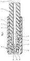
- a jet pipe 1 which consists of a sprayable plastic, such as glass fiber reinforced polyamide.
- the jet pipe 1 has a bore 2.
- a spray nozzle 3 is injected as an insert.
- a worm thread 4 is formed directly, i. H. it is generated at the same time when spraying the jet pipe 1.
- the cap 5 is designed as an elastic tongue, the tongues each having a projection 7 which, when the cap 5 is pushed over the jet pipe 1, engages in the screw thread 4.
- This type of connection between the cap and the jet pipe is not mandatory; For example, it would also be possible to connect using screws that pass through the wall of the cap reach into the screw thread.
- the cap 5 has a slit-shaped opening 8 at its closed end.
- the spray nozzle 3 has a bore 9 which is concentric with the bore 2 and which narrows to form a nozzle 10 at the spray-side end of the spray nozzle. Radial nozzles 11 are drilled into the spray nozzle 3 immediately before the constriction. The spray nozzle 3 also has annular depressions in front of and behind the constriction point for receiving O-rings 12 and 13.
- the cap 5 is shown in a position relative to the jet pipe 1 or the spray nozzle 3, in which, when liquid flows through the bores 2 and 9 into the spray nozzle 3, the latter both through the nozzle 10 and through the radial nozzles 11 is pressed out of the spray nozzle 3.
- the liquid is then swirled in a cavity 14 behind the opening 8 in the cap 5 and then pressed out through the opening 8 in the form of a flat jet.
- the O-ring 12 prevents liquid from moving backwards, i.e. in the direction of the incoming liquid.
- the normally unstructured middle part and the other end of the jet pipe 1 are not shown in FIG. 1.
- the other end will normally have a directly molded-on grip area, but above all a directly molded-on connecting element via which the coupling to a high-pressure cleaning device takes place.
- the connecting element can be designed very differently and requires a matching connecting element in the high-pressure cleaning device.
- the representation in FIG. 2 differs from that in FIG. 1 only in that the cap 5 is in a different position to the jet pipe 1.
- the position is changed by rotating the cap 5, which, since the cap engages with the projections 7 in the worm thread 4, causes the cap to also be moved in the direction of the tube axis during the rotation.
- the spray nozzle 3 extends much further into the cavity 14 than is the case in the illustration shown in FIG. 1. It is essential that, as a result of the tapering of the cavity 14 towards the opening 8, the O-ring 13 presses against the wall of the cavity 14 and thus prevents liquid that has escaped from the nozzles 11 from flowing further. I.e. in other words, only liquid can flow out through the nozzle 10, which is then pressed directly through the opening 8 in the form of a compact jet.
- the pressure resistance of the jet pipe is excellent if the plastic is chosen correctly.
Landscapes
- Spray Control Apparatus (AREA)
Description
- Die Erfindung betrifft ein Strahlrohr für Hochdruckreinigungsgeräte, zum Beispiel für eine Spritzpistole, auf die das Strahlrohr aufgesetzt wird.
- Üblicherweise bestehen Strahlrohre aus Metall. Metall ist von seiner mechanischen Widerstandsfähigkeit her vorteilhaft und seine Bearbeitung wird gut beherrscht. Allerdings ist die Herstellung eines kompliziert geformten Strahlrohres aus Metall nicht einfach und zu montierende Teile können normalerweise nicht ohne zusätzliche Verbindungselemente, wie zum Beispiel Schweiß- oder Lötverbindungen, mit dem Strahlrohr aus Metall verbunden werden. Es kommt hinzu, daß bei Metallteilen im Bedarfsfall besondere Vorkehrungen für die elektrische Isolation und die Wärmeisolation erforderlich sind.
- Es sind auch Vorrichtungen zum Reinigen, Besprühen, Behandeln und Bearbeiten von Flächen, Behältern etc. bekannt, bei denen die Behandlungsflüssigkeit über eine schlauchförmige Leitung und eine Auslaßdüse auf die zu behandelnde Fläche aufgebracht wird (DE-A-3 626 997). Dabei kann der Schlauch in einem Köcher aus Kunststoff aufgenommen werden, dieser Köcher kann in seiner Länge verstellt werden.
- Auch bei dieser Konstruktion erfolgt die Verbindung der eigentlichen Flüssigkeitsleitung mit der Auslaßdüse über einen komplizierten Anschluß.
- Bei Punktstrahl-Rotationsdüsen für Hochdruckreinigungsgeräte ist es an sich bekannt, Hochdruckdüsen in einen Düsenkörper aus Kunststoff einzuspritzen (DE-A-3 832 035). Dabei ist dieser Düsenkörper nur ein kleines Bauteil einer Rotordüse und übernimmt insbesondere keinerlei Abdichtfunktionen. Diese Abdichtfunktion wird auch bei dieser bekannten Rotordüse durch ein Gehäuse aus Metall übernommen.
- Es ist die Aufgabe der Erfindung ein Strahlrohr für Hochdruckreinigungsgeräte anzugeben, welches dieselbe mechanische Widerstandsfähigkeit wie ein metallenes Strahlrohr aufweist, darüberhinaus aber einfach herzustellen ist und ohne weitere Umstände mit zu montierenden Teilen verbunden werden kann.
- Diese Aufgabe wird mit einem Strahlrohr der eingangs genannten Art dadurch gelöst, daß es aus einem spritzbaren Kunststoff besteht und daß an seinem einen Ende eine Sprühdüse aus Metall als Einlegeteil mit eingespritzt ist.
- Das Kunststoffrohr kann in seinen Abmessungen ohne weiteres so ausgelegt werden, daß es bei Betriebsdrücken von 120 bar noch druckfest ist. Es ist außerdem elektrisch und wärmemäßig gut isolierend. Da das Strahlrohr aus einem spritzbaren Kunststoff, wie zum Beispiel aus - gegebenenfalls glasfaserverstärktem - Polyamid besteht, kann ein Strahlrohr mit vielen integrierten Funktionselementen in einem einzigen Arbeitsgang hergestellt werden. Dabei kann auch in vorteilhafter Weise eine aus Metall bestehende Sprühdüse als Einlegeteil druckdicht miteingespritzt werden. Eine Schraubverbindung oder ähnliches ist dabei nicht erforderlich und auch keine zusätzliche Abdichtung.
- Es ist vorteilhaft, wenn das Strahlrohr direkt angeformt ein Verbindungselement zur Verbindung mit der Sprühvorrichtung aufweist.
- Es ist darüberhinaus günstig, wenn passend zu dem Strahlrohr eine Kunststoffkappe mit einer axialen Öffnung vorgesehen ist, die so ausgebildet ist, daß sie, wenn sie über das Ende mit der Sprühdüse gestülpt wird, in ein am Strahlrohr direkt angeformtes Schneckengewinde eingreift. Beim Drehem macht die Kappe auch eine Bewegung parallel zur Rohrachse. Dabei kann der aus der Sprühdüse austretende Strahl geformt werden. Dies erfolgt in vorteilhafter Weise dadurch, daß die Sprühdüse eine axiale Düse und senkrecht dazu Bohrungen aufweist, daß eine Öffnung in der Kunststoffkappe sich zu einem Hohlraum erweitert, der so an die Form der Sprühdüse angepaßt6 ist, daß wenn die Kappe am weitesten über das Strahlrohr gedreht ist, die Sprühdüse an einer Stelle zwischen dem Austritt der axialen Düse und dem der anderen Düsen an der Wand des Hohlraumes anliegt und dadurch die Verbindung zwischen der Öffnung und den weiteren Düsen abschneidet. Man erhält in dieser Kappenstellung einen kompakten Strahl, während, wenn die Düse nicht an der Wand des Hohlraumes anliegt und dann auch Flüssigkeit durch die weiteren Düsen in den Hohlraum in der Kappe gelangen kann, dort eine Verwirblung der Flüssigkeit stattfindet und der austretende Strahl deshalb bei entsprechender Ausbildung der Öffnung z. B. flach ist.
- Weitere vorteilhafte Ausgestaltungen des erfindungsgemäßen Strahlrohres sind in den Unteransprüchen offenbart.
- Die nachfolgende Beschreibung einer bevorzugten Ausführung der Erfindung dient im Zusammenhang mit der Zeichnung der näheren Erläuterung. Es zeigen:
- Fig. 1:
- einen Längsschnitt durch das eine, die Sprühdüse aufweisende Ende des Strahlrohres mit der Kappe in einer ersten Position und
- Fig. 2:
- dieselbe Darstellung wie in Fig. 1, jedoch mit dem Unterschied, daß sich die Kappe in einer zweiten Position befindet.
- In der Fig. 1 ist ein Strahlrohr 1 gezeigt, welches aus einem spritzbaren Kunststoff, wie zum Beispiel glasfaserverstärktem Polyamid, besteht. Das Strahlrohr 1 weist eine Bohrung 2 auf. In das gezeigte Ende des Strahlrohres 1 ist eine Sprühdüse 3 als Einlegeteil mit eingespritzt. In dem Strahlrohr 1 ist ein Schneckengewinde 4 direkt angeformt, d. h. es wird beim Spritzen des Strahlrohres 1 gleich miterzeugt.
- Über das Ende des Strahlrohres 1 und über die Sprühdüse 3 ist eine Kappe 5, welche ebenfalls aus spritzbarem Kunststoff besteht, gestülpt. In zwei einander gegenüberliegenden Wandbereichen 6 ist die Kappe 5 als elastische Zunge ausgebildet, wobei die Zungen je einen Vorsprung 7 aufweisen, der, wenn die Kappe 5 über das Strahlrohr 1 geschoben wird, in das Schnekkengewinde 4 einrastet. Diese Art der Verbindung zwischen der Kappe und dem Strahlrohr ist nicht zwingend; beispielsweise wäre es auch möglich, die Verbindung mittels Schrauben, welche durch die Wand der Kappe hindurch in das Schneckengewinde hineinreichen, vorzunehmen. Die Kappe 5 weist an ihrem geschlossenen Ende eine schlitzförmige Öffnung 8 auf.
- Die Sprühdüse 3 weist eine mit der Bohrung 2 konzentrische Bohrung 9 auf, welche sich am sprühseitigen Ende der Sprühdüse zu einer Düse 10 verengt. Unmittelbar vor der Verengung sind noch radiale Düsen 11 in die Sprühdüse 3 gebohrt. Die Sprühdüse 3 weist außerdem vor und hinter der Verengungsstelle ringförmige Vertiefungen zur Aufnahme von O-Ringen 12 und 13 auf.
- In der Fig. 1 ist die Kappe 5 in einer Stellung zum Strahlrohr 1 bzw. zur Sprühdüse 3 gezeigt, in welcher, wenn Flüssigkeit durch die Bohrungen 2 bzw. 9 in die Sprühdüse 3 einströmt, diese sowohl durch die Düse 10 als auch durch die radialen Düsen 11 aus der Sprühdüse 3 gedrückt wird. Die Flüssigkeit wird dann in einem Hohlraum 14 hinter der Öffnung 8 in der Kappe 5 verwirbelt und dann in Form eines flachen Strahles durch die Öffnung 8 hinausgedrückt. Der O-Ring 12 verhindert, daß Flüssigkeit nach hinten, d.h. in Richtung der ankommenden Flüssigkeit, gedrückt wird.
- Nicht gezeigt in der Fig. 1 ist das normalerweise unstrukturierte Mittelteil und das andere Ende des Strahlrohres 1. Das andere Ende wird normalerweise einen direkt angeformten Griffbereich, vor allem aber ein direkt angeformtes Verbindungselement, über das die Ankopplung an ein Hochdruckreinigungsgerät erfolgt, aufweisen. Das Verbindungselement kann sehr unterschiedlich ausgebildet sein und erfordert ein dazu passendes Verbindungselement in dem Hochdruckreinigungsgerät.
- Wie bereits erwähnt unterscheidet sich die Darstellung in der Fig. 2 von der in der Fig. 1 nur dadurch, daß sich die Kappe 5 in einer anderen Position zum Strahlrohr 1 befindet. Die Veränderung der Position erfolgt durch eine Drehung der Kappe 5, was, da die Kappe mit den Vorsprüngen 7 in das Schneckengewinde 4 eingreift, bewirkt, daß bei der Drehung die Kappe auch in Richtung der Rohrachse bewegt wird.
- In der in der Fig. 2 gezeigten Kappenposition reicht die Sprühdüse 3 viel weiter in den Hohlraum 14 hinein als dies bei der in der Fig. 1 gezeigten Darstellung der Fall ist. Wesentlich ist dabei, daß infolge der Verjüngung des Hohlraumes 14 zur Öffnung 8 hin der O-Ring 13 gegen die Wand des Hohlraumes 14 drückt und damit verhindert, daß Flüssigkeit, welche aus den Düsen 11 ausgetreten ist, weiterströmen kann. D.h. mit anderen Worten, daß nur Flüssigkeit durch die Düse 10 ausströmen kann, die dann direkt in Form eines Kompaktstrahles durch die Öffnung 8 gedrückt wird. Die Druckfestigkeit des Strahlrohres ist bei richtiger Wahl des Kunststoffes hervorragend. Wird wie im vorliegenden Fall glasfaserverstärktes Polyamid verwendet, ist bei einer Wandstärke des Strahlrohres von nur ungefähr 0,6 cm und bei eingespritzter Sprühdüse 3 Druckfestigkeit bis zu einem Betriebsdruck von 120 bar gewährleistet. Dadurch kommt als weiterer Vorteil gegenüber Metallrohren das geringe Gewicht des erfindungsgemäßen Strahlrohres hinzu.
Claims (6)
- Strahlrohr für Hochdruckreinigungsgeräte, auf die das Strahlrohr aufgesetzt wird, dadurch gekennzeichnet, daß es aus einem spritzbaren Kunststoff besteht und daß an seinem einen Ende eine Sprühdüse (3) aus Metall als Einlegeteil mit eingespritzt ist.
- Strahlrohr nach Anspruch 1, dadurch gekennzeichnet, daß das Strahlrohr aus glasfaserverstärktem Polyamid besteht.
- Strahlrohr nach einem der vorangegangenen Ansprüche, dadurch gekennzeichnet, daß es direkt angeformt ein Verbindungselement zum Hochdruckreinigungsgerät aufweist.
- Strahlrohr nach einem der vorangegangenen Ansprüche, dadurch gekennzeichnet, daß passend zu dem Strahlrohr (1) eine mit einer axialen Öffnung (8) versehene Kunststoffkappe (5) vorgesehen ist, die so ausgebildet ist, daß sie, wenn sie über das Ende mit der Sprühdüse (3) gestülpt wird, in ein am Strahlrohr (1) direkt angeformtes Schneckengewinde (4) eingreift.
- Strahlrohr nach Anspruch 4, dadurch gekennzeichnet, daß zwei einander gegenüberliegende Wandbereiche der Kunststoffkappe (5) als elastische Zunge (16) ausgebildet sind, welche Vorsprünge (7) aufweisen, die in das Schneckengewinde (4) einrasten können.
- Strahlrohr nach Anspruch 4 oder 5, dadurch gekennzeichnet, daß die Sprühdüse (3) in axialer Richtung eine Düse (9) und senkrecht dazu Düsen (11) aufweist, daß die Öffnung (8) in der Kunststoffkappe (5) sich zu einem Hohlraum (14) erweitert, der so an die Form der Sprühdüse (3) angepaßt ist, daß, wenn die Kappe am weitesten über das Strahlrohr gedreht ist, die Sprühdüse (3) an einer Stelle zwischen dem Austritt der Düse (9) und dem der Düsen (11) an der Wand des Hohlraumes (14) anliegt und dadurch die Verbindung zwischen der Öffnung (8) und den Düsen (11) abschneidet.
Applications Claiming Priority (2)
| Application Number | Priority Date | Filing Date | Title |
|---|---|---|---|
| DE4014825 | 1990-05-09 | ||
| DE4014825 | 1990-05-09 |
Publications (3)
| Publication Number | Publication Date |
|---|---|
| EP0456010A2 EP0456010A2 (de) | 1991-11-13 |
| EP0456010A3 EP0456010A3 (en) | 1992-05-13 |
| EP0456010B1 true EP0456010B1 (de) | 1995-07-05 |
Family
ID=6406001
Family Applications (1)
| Application Number | Title | Priority Date | Filing Date |
|---|---|---|---|
| EP91106083A Expired - Lifetime EP0456010B1 (de) | 1990-05-09 | 1991-04-17 | Strahlrohr für Hochdruckreinigungsgeräte |
Country Status (3)
| Country | Link |
|---|---|
| EP (1) | EP0456010B1 (de) |
| DE (1) | DE59105905D1 (de) |
| DK (1) | DK0456010T3 (de) |
Cited By (1)
| Publication number | Priority date | Publication date | Assignee | Title |
|---|---|---|---|---|
| WO2000047329A1 (de) | 1999-02-12 | 2000-08-17 | Alfred Kärcher GmbH & Co. | Strahlrohr für hochdruckreinigungsgeräte |
Families Citing this family (3)
| Publication number | Priority date | Publication date | Assignee | Title |
|---|---|---|---|---|
| GB2355676B (en) * | 1999-09-20 | 2003-07-09 | Lurmark Ltd | Spray nozzle and method of manufacture |
| CN105949763A (zh) * | 2016-05-16 | 2016-09-21 | 上海日之升科技有限公司 | 一种环保型良外观热水稳定聚酰胺组合物及其制备方法 |
| CN114352022A (zh) * | 2022-01-23 | 2022-04-15 | 陆越 | 一种可自主清洗式的混凝土喷射管 |
Family Cites Families (3)
| Publication number | Priority date | Publication date | Assignee | Title |
|---|---|---|---|---|
| FR1125186A (fr) * | 1955-04-29 | 1956-10-25 | Carbures Metalliques Et Derive | Perfectionnement aux buses de sablage |
| DE3626997A1 (de) * | 1986-08-08 | 1988-02-11 | Duo Geraetetechnik Gmbh | Vorrichtung zum verspruehen duennfluessiger medien |
| DE3832035A1 (de) * | 1988-06-10 | 1989-12-07 | Suttner Gmbh & Co Kg | Punktstrahl-rotationsduese fuer hochdruckreinigungsgeraete |
-
1991
- 1991-04-17 DE DE59105905T patent/DE59105905D1/de not_active Expired - Lifetime
- 1991-04-17 DK DK91106083.8T patent/DK0456010T3/da active
- 1991-04-17 EP EP91106083A patent/EP0456010B1/de not_active Expired - Lifetime
Cited By (1)
| Publication number | Priority date | Publication date | Assignee | Title |
|---|---|---|---|---|
| WO2000047329A1 (de) | 1999-02-12 | 2000-08-17 | Alfred Kärcher GmbH & Co. | Strahlrohr für hochdruckreinigungsgeräte |
Also Published As
| Publication number | Publication date |
|---|---|
| EP0456010A3 (en) | 1992-05-13 |
| EP0456010A2 (de) | 1991-11-13 |
| DE59105905D1 (de) | 1995-08-10 |
| DK0456010T3 (da) | 1995-08-21 |
Similar Documents
| Publication | Publication Date | Title |
|---|---|---|
| DE3603344C2 (de) | ||
| DE3143015C3 (de) | Drehbare Schnellkupplung | |
| DE2901306A1 (de) | Schnelltrennduese | |
| DE2820226A1 (de) | Elektrischer schnelltrenn-verbinder | |
| EP0559938B1 (de) | Durchflussmesseinrichtung für flüssige Medien nach dem Ultraschall-Laufzeitprinzip | |
| EP1672265B1 (de) | Verbindungsanordnung für eine Fluidleitung, insbesondere Hahnstück | |
| EP1264127B1 (de) | Drehbarer absperrhahn für eine steckkupplung mit abgewinkeltem anschlussstutzen | |
| EP0386589B1 (de) | Wasserauslaufarmatur | |
| DE3608843A1 (de) | Zweiteiliger metallischer klemmverbinder | |
| EP0456010A2 (de) | Strahlrohr für Hochdruckreinigungsgeräte | |
| DE9005274U1 (de) | Strahlrohr für Hochdruckreinigungsgeräte | |
| EP1029192A1 (de) | Verbindungs- und anschlussstück für wellrohre | |
| EP2420195B1 (de) | Vorrichtung zum fluidführenden Anschluss wenigstens einer Applikationssonde an einen Versorgungsschlauchsatz und Handgriff für ein Chirurgieinstrument | |
| EP0727173B1 (de) | Staubsaugerschlauch mit einem Griffstück | |
| DE102018121733A1 (de) | Kanüle | |
| EP0727172A1 (de) | Saugwerkzeug mit einer Rohrsteckkupplung | |
| DE9005930U1 (de) | Schraubanschluß für einen Duschenschlauch | |
| DE4402475C2 (de) | Mittels Tuohy-Nadel plazierbarer Katheter | |
| DE3024114C2 (de) | Umschaltvorrichtung für ein Hochdruckreinigungsgerät | |
| DE1928177A1 (de) | Gasdichte flexible Verbindungsleitung | |
| DE3320492A1 (de) | Tankgeraet | |
| DE202004013983U1 (de) | Verbindungs- und Anschlussstück für Wellrohre | |
| DE3347239C2 (de) | ||
| DE9005273U1 (de) | Strahlrohr mit Verbindungselement für Hochdruckreinigungsgeräte | |
| EP0456009A1 (de) | Strahlrohr mit Verbindungselement für Hochdruckreinigungsgeräte |
Legal Events
| Date | Code | Title | Description |
|---|---|---|---|
| PUAI | Public reference made under article 153(3) epc to a published international application that has entered the european phase |
Free format text: ORIGINAL CODE: 0009012 |
|
| AK | Designated contracting states |
Kind code of ref document: A2 Designated state(s): DE DK IT |
|
| PUAL | Search report despatched |
Free format text: ORIGINAL CODE: 0009013 |
|
| AK | Designated contracting states |
Kind code of ref document: A3 Designated state(s): DE DK IT |
|
| 17P | Request for examination filed |
Effective date: 19920618 |
|
| 17Q | First examination report despatched |
Effective date: 19930824 |
|
| GRAA | (expected) grant |
Free format text: ORIGINAL CODE: 0009210 |
|
| ITF | It: translation for a ep patent filed | ||
| AK | Designated contracting states |
Kind code of ref document: B1 Designated state(s): DE DK IT |
|
| REF | Corresponds to: |
Ref document number: 59105905 Country of ref document: DE Date of ref document: 19950810 |
|
| REG | Reference to a national code |
Ref country code: DK Ref legal event code: T3 |
|
| PLBE | No opposition filed within time limit |
Free format text: ORIGINAL CODE: 0009261 |
|
| STAA | Information on the status of an ep patent application or granted ep patent |
Free format text: STATUS: NO OPPOSITION FILED WITHIN TIME LIMIT |
|
| 26N | No opposition filed | ||
| PGFP | Annual fee paid to national office [announced via postgrant information from national office to epo] |
Ref country code: DK Payment date: 20040419 Year of fee payment: 14 |
|
| PG25 | Lapsed in a contracting state [announced via postgrant information from national office to epo] |
Ref country code: DK Free format text: LAPSE BECAUSE OF NON-PAYMENT OF DUE FEES Effective date: 20050502 |
|
| REG | Reference to a national code |
Ref country code: DK Ref legal event code: EBP |
|
| PGFP | Annual fee paid to national office [announced via postgrant information from national office to epo] |
Ref country code: IT Payment date: 20100423 Year of fee payment: 20 Ref country code: DE Payment date: 20100526 Year of fee payment: 20 |
|
| REG | Reference to a national code |
Ref country code: DE Ref legal event code: R071 Ref document number: 59105905 Country of ref document: DE |
|
| PG25 | Lapsed in a contracting state [announced via postgrant information from national office to epo] |
Ref country code: DE Free format text: LAPSE BECAUSE OF EXPIRATION OF PROTECTION Effective date: 20110417 |