EP0455897B1 - Apparatus for the preparation of very fine fibres - Google Patents
Apparatus for the preparation of very fine fibres Download PDFInfo
- Publication number
- EP0455897B1 EP0455897B1 EP90250121A EP90250121A EP0455897B1 EP 0455897 B1 EP0455897 B1 EP 0455897B1 EP 90250121 A EP90250121 A EP 90250121A EP 90250121 A EP90250121 A EP 90250121A EP 0455897 B1 EP0455897 B1 EP 0455897B1
- Authority
- EP
- European Patent Office
- Prior art keywords
- gas
- bores
- melt
- melting
- spinning
- Prior art date
- Legal status (The legal status is an assumption and is not a legal conclusion. Google has not performed a legal analysis and makes no representation as to the accuracy of the status listed.)
- Expired - Lifetime
Links
Images
Classifications
-
- D—TEXTILES; PAPER
- D01—NATURAL OR MAN-MADE THREADS OR FIBRES; SPINNING
- D01D—MECHANICAL METHODS OR APPARATUS IN THE MANUFACTURE OF ARTIFICIAL FILAMENTS, THREADS, FIBRES, BRISTLES OR RIBBONS
- D01D4/00—Spinnerette packs; Cleaning thereof
- D01D4/02—Spinnerettes
- D01D4/025—Melt-blowing or solution-blowing dies
-
- D—TEXTILES; PAPER
- D01—NATURAL OR MAN-MADE THREADS OR FIBRES; SPINNING
- D01D—MECHANICAL METHODS OR APPARATUS IN THE MANUFACTURE OF ARTIFICIAL FILAMENTS, THREADS, FIBRES, BRISTLES OR RIBBONS
- D01D5/00—Formation of filaments, threads, or the like
- D01D5/08—Melt spinning methods
- D01D5/098—Melt spinning methods with simultaneous stretching
- D01D5/0985—Melt spinning methods with simultaneous stretching by means of a flowing gas (e.g. melt-blowing)
Definitions
- the invention relates to a device for producing fine threads according to the preamble of the main claim.
- the arrangement of the melt bores in a row with an overlying distribution channel and air outlet slots lying close to the bores is basically a weak construction, both in terms of the deformation of the slot by the air pressure - 0.5 to 6 bar and above are used - as well as the deformation of the elongated melt distribution space.
- U.S. Patent No. 4,486,161 a device of this type is protected in which the opposing melt walls are connected by webs in order to increase the resistance to inflation.
- a spinning head which has a first plate connected to the melt feed and a second plate also fastened, a gas distribution space being provided between the two plates and being connected to a gas feed.
- a plurality of nozzle elements are screwed into the second plate, the melt bores connected on the one hand with the melt supply and on the other hand into the gas distribution space have opening channels for the emerging threads or fibers surrounding gas streams.
- the nozzle elements consist of several parts, so that the structure is complicated.
- US-A-3 954 361 describes a device for producing threads from a melt-spinnable plastic material which has a spinning head surrounding a melt chamber, in which a plurality of tubes are inserted in a row, which protrude beyond the lower end of the head. Around the head are at a distance from this. two air duct walls are arranged, which have a slot receiving the row of tubes. The air flows through the air duct and to the outside between the tubes and air duct walls spinning the threads.
- the invention has for its object to provide a device for producing fine threads, the one hand continuous fine threads or fibers without thread breaks with a diameter between 5 to 10 microns or particularly thin threads in the range against 1 micron, the do not have to be endless, can supply and which have an improved distribution of the gas or air flow with respect to the individual threads emerging from the spinning head and allow a higher melt throughput, the construction of the spinning head should be simple.
- each Melt thread therefore has its own blowing nozzle.
- the present invention it is possible to produce continuous (or endless) fine threads, as are desired in the textile technology for particularly fine-titer yarns for the production of women's stockings or fine capillary fabrics with high thermal insulation and at the same time possible moisture transport for good physiological wearing properties.
- the single thread of a yarn composed of several such should have a fineness of less than 1 denier per filament.
- 1 denier (den) is the weight of a thread of length 9,000 m
- decitex decitex
- the weight in g also refers to 10,000 m thread length.
- each bore or spinning opening in the spinneret is assigned an individual blowing nozzle, the blowing nozzles being connected to a gas supply, gives a very good gas distribution with respect to the individual threads. Since the gas flow is applied evenly to the threads, there are no thread breaks and the diameter of the threads after they have cooled is essentially constant.
- the design of the spinnerets is not as limited in the design and construction of the spinning heads as in the prior art, in which only a limited number of spinning orifices can be provided.
- the design of the spinning head is very simple and inexpensive due to the specially designed plates with the elevations engaging in bores.
- meltblown fibers that have been used in many areas such as filtration, absorption and insulation in technical, medical, textile tasks.
- the difference to the production of continuous or endless threads is that generally higher melt temperatures and above all higher air velocities, ie also air pressures, are used to avoid high shear stresses to pull out the thread to the appropriate fineness.
- melt temperatures and above all higher air velocities ie also air pressures
- the spin pack 1 shown in FIG. 1 is part of a spinning head which is used for pressing thermoplastic melts in the production of blow-spun threads.
- the spin pack is connected via a melt line 2 to a pump part, not shown.
- the spin pack has a housing consisting of two parts 3, 4 which are screwed together: in the lower part of the housing 3, 4 there is a spinneret 5, which is described in more detail below.
- a large number of melt bores 6 lying next to one another are provided in the spinneret 5.
- a support plate 7 is supported on the spinneret, which has a plurality of through holes 8 for passing the melt through.
- a filter unit 9 is located above the support plate 7 and a displacement body 10 is arranged above it, which defines a specific space for the passage of the melt entering via the melt line 2.
- the melt flow during the transition from one component to the other is sealed by soft metal seals such as aluminum.
- the spinneret 5 which for the sake of clarity is shown in FIG. 1 only with a few melt bores 6 not to scale, FIG. 3 showing a section, has a circular cross section and consists of two plates 11, 12 which are screwed together.
- the upper plate 11, which is provided with the melt bores 6, has a plurality of conical elevations 13 around the melt bores 6.
- the lower plate 12 is designed in such a way that it has conical openings 14 which correspond to the elevations 13, the elevations 13 projecting into the conical openings 14 when the plates 11, 12 are screwed together, so that there is between the outer surface of the elevations 13 and the inner surface of the conical bores 14 each form an annular channel or an annular gap.
- the arrangement consisting of the inner surface of the bore 14 surrounding the melt bore 6 and the annular outer surface of the elevation 13 located in the lower counterplate 12, form a blow nozzle 16.
- the individual blow nozzles 16 surrounding the melt bore 6 are connected to a gas distribution space 17 which by appropriate Formations between the plates 11 and 12 is formed.
- the cross section for the inflow to the individual blowing nozzles 16 is several times larger than the cross section of the annular gap 15 for the purpose of the best possible distribution.
- the gas (air) can be heated directly in the spinning head.
- spinnerets are heated by a liquid or vaporous organic heat transfer medium, the temperature of which is that of the desired melt temperature.
- the gas supply lines can be guided in the spinning head and the gas can also be brought to melt temperature if a sufficiently large heat transfer area is provided. This leads to a particularly compact and simple control device. However, no variations in the gas temperature above or below the melt temperature are then possible.
- the hot gas flows concentrically surrounding the melt bore 6 and leaving the blowing nozzle 16 facilitate the warping of the thread to thinner diameters, which are distorted by gravity, but especially by the tensile forces exerted by the winding unit, and are molecularly oriented depending on the speed.
- the hot gas jet mixes with the ambient air and takes on an increasingly lower mixing temperature.
- the melt temperature of the spun polymeric or other thread-forming raw material falls below, the thread begins to solidify to its final diameter. Finer threads can be achieved in that the throughput is reduced at the same winding speed and, if breaks occur, the air and melt temperature are increased, which is possible up to a certain limit.
- meltblown fine fibers For the production of meltblown fine fibers, a gas heater, mostly electrically heated, which is independent of the temperature of the spinning head is used, through which the gas flows and is then no longer fed through the heating chamber of the spinning head to the nozzle. This can be done constructively in the same way as shown in FIG. 1. Another possibility is to lead the heated gas to the side of the spinneret and then to connect it to the spinneret with the melt opening arranged at the side by pressing against the melt and gas openings with seals. The gas temperature can then be significantly higher than the melt temperature, which produces finer fibers.
- melt-blown fine fibers mostly in the range significantly below 10 ⁇ m and definitely below 1 ⁇ m, are usually deposited in a random form as a fleece.
- the gas flows from the blowing nozzles 16, mixed with the ambient air below the spinnerets, flow laterally or flow through the fleece.
- the fleece made of fine fibers or threads can also be spun directly onto a carrier material.
- the device according to the invention avoids the disadvantages known hitherto, in which the narrow, flat air gap has to be readjusted after each nozzle cleaning.
- this gap arises automatically if only an accuracy that can be achieved with today's machine tools was pursued in the manufacture of the two halves 11 and 12, that is to say the melt bore 6 and the conical bore 14 have the same center with sufficient tolerance.
- a deviation of a few hundredths of a millimeter is permissible for Annular gaps 15 from 0.2 to 0.6 mm.
- one will use the same material for the two parts 11 and 12, so that there are no different thermal expansions.
- the two parts are fitted with fits on the edges using the usual toolmaking technology.
- the spinning bores 6 and the blowing nozzles 16 surrounding them are arranged distributed on a circular cross section.
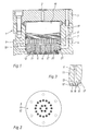
- the melt bores 6 can be distributed as desired on a nozzle face. 2 this was shown for a circular nozzle, the individual melt bores 6 and thus also the blowing nozzles 16 being arranged on concentric circles. But they can also be arranged in a row, with the advantage of more precise maintenance of the air gap compared to the previous devices, or in several rows next to each other.
- Such multi-row longitudinal nozzles with a large number of holes are recommended for the production of fine or microfibers, which are collected as a fleece, while round nozzles can be used for the production of endless textile fine threads for later processing in fabrics or knitted fabrics. So it is also conceivable that in this way cables are made from the finest threads that are later cut into staple fibers. Both round and rectangular nozzles are to be used.
- the principle of the invention is not limited to the shape of the nozzle.
- the spinning head had air tubes which led through a heating room heated with diphyl steam and ended in the fastening surface of the spinning pack.
- a spinneret with a diameter of 60 mm was screwed into the spin pack 1, which had the characteristics according to the invention essentially according to FIG. 1.
- the number of holes in the nozzles was 12 and the diameter of the melt bore was 0.25 mm.
- the lower part 12 of the spinneret formed 14 annular gaps 15 of 0.4 mm width with the cone of the spinning bores 14.
- the temperature of the polyamide melt was 228 ° C. and the air fed to the spinneret was practically the same temperature.
- the air volume was 1.8 Nm3 / h.
- the amount of melt distributed over the twelve holes was 3 g / min.
- the arrangement corresponded to the usual melt spinning device for synthetic threads.
- a blow chute in which air of 25 ° C and 40% rel. Moisture was blown in at a speed of 0.3 m / s to cool the threads.
- the threads were wound up by a high-speed winder at a speed of 5540 m / min.
- the titer was 12 x 0.45 dtex, which corresponds to a diameter of the individual capillary of approximately 7.2 ⁇ m.
- the average diameter of the fibers was 4 to 5 ⁇ m, with the smallest of 2 ⁇ m and the largest of 6 ⁇ m.
- the determination of the thread diameter was carried out on a microscope.
Abstract
Description
Die Erfindung betrifft eine Vorrichtung zum Herstellen von Feinstfäden nach dem Oberbegriff des Hauptanspruchs.The invention relates to a device for producing fine threads according to the preamble of the main claim.
Aus der US-PS 3 379 811 ist eine Vorrichtung und ein Verfahren zur Herstellung von Fäden bekannt, bei denen eine langgestreckte Spinndüse vorgesehen ist, der eine Vielzahl von koplanaren Spinnöffnungen aufweist, denen Polymer zugeführt wird. Beidseitig zu den Spinnöffnungen sind Luft- oder Gaskanäle vorgesehen, die mit einer Luft- oder Gaszuführung verbunden sind. Aus dem Spinnkopf tritt eine Reihe von Fäden aus und die aus den Kanälen beidseitig der Reihe austretende Luft oder das Gas trifft auf die Fäden mit einer Geschwindigkeit, die größer ist als die Fadengeschwindigkeit, wodurch die Fäden von dem Gasstrom mitgezogen werden.From US Pat. No. 3,379,811 a device and a method for producing threads is known, in which an elongated spinneret is provided which has a multiplicity of coplanar spinning orifices to which polymer is fed. Air or gas channels, which are connected to an air or gas supply, are provided on both sides of the spinning openings. A series of threads emerge from the spinning head and the air or gas exiting the channels on both sides of the series hits the threads at a speed greater than the thread speed, thereby pulling the threads with the gas stream.
Bei den bisher bekanntgewordenen Vorrichtungen, bei denen wie in der vorgenannten Patentschrift oder in der wohl ersten Veröffentlichung dieser Art von V.A. Wente in Tech. Rep. No. PB111437 des Naval Research Laboratory (1954) oder in Industrial and Engineering Chemistry, 48 (1954) 1342-46 sind die Schmelzeaustrittsbohrungen in einer Reihe angeordnet und heiße Luftströme treten aus seitlich dazu angeordneten Schlitzen aus. Die Problem liegen zum einen darin, daß es schwierig ist oder erheblichen Aufwand bedeutet, diese Luftaustrittsschlitze über größere Düsenbreiten hin in konstanten Breiten zu halten, zum anderen die Luftströmung konstant über solche Breiten austreten zu lassen, was bei unterschiedlichen Spaltbreiten schon gar nicht mehr möglich ist. Bei der Anordnung der Schmelzebohrungen in einer Reihe mit darüberliegendem Verteilerkanal und dicht neben den Bohrungen liegenden Luftaustrittsschlitzen handelt es sich grundsätzlich um eine festigkeitsmäßig schwache Konstruktion, sowohl was die Verformung des Schlitzes durch den Luftdruck - es werden 0,5 bis 6 bar und darüber angewandt - als auch, was die Verformung des langgestreckten Schmelzeverteilungsraumes anbetrifft. In der US-PS 4 486 161 wird eine Vorrichtung dieser Art geschützt, in der die gegenüberliegenden Schmelzewände durch Stege verbunden sind, um die Festigkeit gegen Aufblähen zu vergrößern.In the devices which have become known so far, in which, as in the aforementioned patent specification or in the probably first publication of this type of V.A. Wente in Tech. Rep. No. PB111437 from the Naval Research Laboratory (1954) or in Industrial and Engineering Chemistry, 48 (1954) 1342-46, the melt outlet bores are arranged in a row and hot air currents emerge from slots arranged on the side. The problem is, on the one hand, that it is difficult or considerable effort to keep these air outlet slots in constant widths over larger nozzle widths, on the other hand, to let the air flow emerge constantly over such widths, which is no longer possible with different gap widths . The arrangement of the melt bores in a row with an overlying distribution channel and air outlet slots lying close to the bores is basically a weak construction, both in terms of the deformation of the slot by the air pressure - 0.5 to 6 bar and above are used - as well as the deformation of the elongated melt distribution space. In U.S. Patent No. 4,486,161 a device of this type is protected in which the opposing melt walls are connected by webs in order to increase the resistance to inflation.
Aus der US-A-3 888 610 ist ein Spinnkopf bekannt, der eine mit der Schmelzezuführung verbundene erste Platte und eine mitbefestigte zweite Platte aufweist, wobei zwischen beiden Platten ein Gasverteilungsraum vorgesehen ist, der mit einer Gaszufuhr verbunden ist. In die zweite Platte ist eine Vielzahl von Düsenelementen eingeschraubt, die einerseits mit der Schmelzezufuhr verbundene Schmelzebohrungen und andererseits in den Gasverteilungsraum mündende Kanäle für die austretenden Fäden oder Fasern umgebende Gasströme aufweisen. Die Düsenelemente bestehen aus mehreren Teilen, so daß der Aufbau kompliziert ist.From US-A-3 888 610 a spinning head is known which has a first plate connected to the melt feed and a second plate also fastened, a gas distribution space being provided between the two plates and being connected to a gas feed. A plurality of nozzle elements are screwed into the second plate, the melt bores connected on the one hand with the melt supply and on the other hand into the gas distribution space have opening channels for the emerging threads or fibers surrounding gas streams. The nozzle elements consist of several parts, so that the structure is complicated.
Die US-A-3 954 361 beschreibt eine Vorrichtung zum Herstellen von Fäden aus einem schmelzspinnbarem Kunststoffmaterial, die einen eine Schmelzekammer umgebenden Spinnkopf aufweist, in den eine Vielzahl von Röhrchen in einer Reihe eingesetzt sind, die über das untere Ende des Kopfes herausragen. Um den Kopf herum sind mit Abstand zu diesem. zwei Luftkanalwände angeordnet, die einen die Reihe von Röhrchen aufnehmenden Schlitz aufweisen. Die Luft strömt durch den Luftkanal und zwischen den die Fäden ausspinnenden Röhrchen und Luftkanalwänden nach außen.US-A-3 954 361 describes a device for producing threads from a melt-spinnable plastic material which has a spinning head surrounding a melt chamber, in which a plurality of tubes are inserted in a row, which protrude beyond the lower end of the head. Around the head are at a distance from this. two air duct walls are arranged, which have a slot receiving the row of tubes. The air flows through the air duct and to the outside between the tubes and air duct walls spinning the threads.
Ausgehend von diesem Stand der Technik liegt der Erfindung die Aufgabe zugrunde, eine Vorrichtung zum Herstellen von Feinstfäden zu schaffen, die einerseits kontinuierliche Feinstfäden oder -fasern ohne Fadenrisse mit einem Durchmesser zwischen 5 bis 10 µm oder besonders dünne Fäden im Bereich gegen 1 µm, die nicht endlos sein müssen, liefern können und die eine verbesserte Verteilung des Gas- oder Luftstromes in bezug auf die einzelnen aus dem Spinnkopf austretenden Fäden aufweisen und einen höheren Schmelzedurchsatz gestatten, wobei die Konstruktion des Spinnkopfes einfach sein soll.Based on this prior art, the invention has for its object to provide a device for producing fine threads, the one hand continuous fine threads or fibers without thread breaks with a diameter between 5 to 10 microns or particularly thin threads in the range against 1 micron, the do not have to be endless, can supply and which have an improved distribution of the gas or air flow with respect to the individual threads emerging from the spinning head and allow a higher melt throughput, the construction of the spinning head should be simple.
Die erfindungsgemäße Vorrichtung zur Herstellung von Feinstfäden oder -fasern vermeidet die Nachteile des Standes der Technik, indem jeder einzelnen Schmelzeaustrittsöffnung ein sie rotationssymmetrisch umschließender Luft- oder Gasaustrittsschlitz zugeordnet ist, jeder Schmelzefaden also seine eigene Blasdüse hat. Das ergibt eine höhere Symmetrie der Strömung und damit eine höhere Gleichmäßigkeit bei der Fadenbildung, verglichen mit Flachstrahlen, die in bestimmten Abständen immer wieder von austretenden Fäden unterbrochen werden, eine weitaus höhere Zahl von Schmelzeaustrittsbohrungen pro Flächeneinheit der Spinndüsenstirnfläche, was zum Zwecke des höheren Durchsatzes und damit höherer Wirtschaftlichkeit in aller Regel gefordert wird, und eine weitaus höhere Festigkeit der Kombination Blasdüse-Spinndüse (Schmelzeaustrittsöffnung) als bei den beschriebenen linearen Anordnungen nach dem Stand der Technik.The device according to the invention for the production of very fine threads or fibers avoids the disadvantages of the prior art, in that each individual melt outlet opening is assigned an air or gas outlet slot enclosing it in a rotationally symmetrical manner, each Melt thread therefore has its own blowing nozzle. This results in a higher symmetry of the flow and thus a higher uniformity in the thread formation, compared to flat jets that are interrupted at certain intervals by emerging threads, a much higher number of melt outlet holes per unit area of the spinneret face, which is for the purpose of higher throughput and This means that higher efficiency is generally required, and a much higher strength of the combination of the blowing nozzle and the spinneret (melt outlet opening) than in the described linear arrangements according to the prior art.
Mit der vorliegenden Erfindung ist es möglich, kontinuierliche (oder endlose) Feinstfäden herzustellen, wie sie Meute in der Textiltechnik gewünscht werden für besonders feintitrige Garne zur Herstellung von Damenstrümpfen oder feinkapillaren Geweben mit hoher Wärmeisolation bei gleichzeitig möglichem Feuchtigkeitstransport für gute physiologische Trageeigenschaften. Der Einzelfaden eines aus mehreren solchen zusammengesetzten Garns soll eine Feinheit unter 1 Denier pro Filament haben. 1 Denier (den) ist das Gewicht eines Fadens der Länge von 9.000 m, ein anderes Maß ist Decitex (dtex), wobei sich das Gewicht ebenfalls in g auf 10.000 m Fadenlänge bezieht.With the present invention it is possible to produce continuous (or endless) fine threads, as are desired in the textile technology for particularly fine-titer yarns for the production of women's stockings or fine capillary fabrics with high thermal insulation and at the same time possible moisture transport for good physiological wearing properties. The single thread of a yarn composed of several such should have a fineness of less than 1 denier per filament. 1 denier (den) is the weight of a thread of length 9,000 m, another measure is Decitex (dtex), whereby the weight in g also refers to 10,000 m thread length.
Dadurch, daß jeder Bohrung bzw. Spinnöffnung in der Spinndüse eine individuelle Blasdüse zugeordnet ist, wobei die Blasdüsen mit einer Gaszuführung verbunden sind, ist eine sehr gute Gasverteilung in bezug auf die einzelnen Fäden gegeben. Da der Gasstrom gleichmäßig auf die Fäden aufgebracht wird, treten keine Fadenrisse auf und der Durchmesser der Fäden nach ihrer Abkühlung ist im wesentlichen konstant. Darüber hinaus ist der Konstrukteur der Spinndüsen in dem Entwurf und dem Aufbau der Spinnköpfe nicht so eingeschränkt wie im Stand der Technik, bei dem nur eine begrenzte Anzahl von Spinnöffnungen vorgesehen werden können. Die Konstruktion des Spinnkopfes ist aufgrund der besonders ausgebildeten Platten mit den in Bohrungen eingreifenden Erhebungen sehr einfach und kostengünstig.The fact that each bore or spinning opening in the spinneret is assigned an individual blowing nozzle, the blowing nozzles being connected to a gas supply, gives a very good gas distribution with respect to the individual threads. Since the gas flow is applied evenly to the threads, there are no thread breaks and the diameter of the threads after they have cooled is essentially constant. In addition, the design of the spinnerets is not as limited in the design and construction of the spinning heads as in the prior art, in which only a limited number of spinning orifices can be provided. The design of the spinning head is very simple and inexpensive due to the specially designed plates with the elevations engaging in bores.
Auch ist es erfindungsgemäß möglich, besonders dünne Fäden im Bereich gegen 1 µm zu erzeugen, wobei diese nicht endlos sein müssen. Es handelt sich dabei um schmelzgeblasene Fasern, die eine vielfache Anwendung in Gebieten wie der Filtration, der Absorption und der Isolierung gefunden haben in technischen, medizinischen, textilen Aufgabenstellungen. Der Unterschied zur Herstellung von kontinuierlichen oder endlosen Fäden besteht darin, daß in der Regel mit höheren Schmelzetemperaturen und vor allem höheren Luftgeschwindigkeiten, also auch Luftdrücken gearbeitet wird, um durch hohe Schubspannungen den Faden zu entsprechender Feinheit auszuziehen. Dabei spielt es im allgemeinen keine Rolle, wenn er abreißt; es sich also um endlich lange Fasern oder auch nur sehr kurze Fibrillen handelt, wenn sich nur keine starken Tropfen, die die aus den Feinstfasern gebildete Kapillarstruktur für den besonderen Anwendungszweck stören würden, bilden. Beides wird durch die gleichmäßige Umströmung des schmelzflüssigen Fadens erzielt.It is also possible according to the invention to produce particularly thin threads in the range of around 1 μm, which need not be endless. These are meltblown fibers that have been used in many areas such as filtration, absorption and insulation in technical, medical, textile tasks. The difference to the production of continuous or endless threads is that generally higher melt temperatures and above all higher air velocities, ie also air pressures, are used to avoid high shear stresses to pull out the thread to the appropriate fineness. In general, it does not matter if it breaks off; it is therefore a question of finitely long fibers or even very short fibrils if only there are no strong drops which would disrupt the capillary structure formed from the fine fibers for the particular application. Both are achieved by the even flow around the molten thread.
Ein Ausführungsbeispiel der Erfindung ist in der Zeichnung dargestellt und wird in der nachfolgenden Beschreibung näher erläutert. Es zeigen:
- Fig. 1
- einen Schnitt durch ein Spinnpack,
- Fig. 2
- eine Ansicht von unten auf die Spinnbohrungen mit Blasdüsen, und
- Fig. 3
- einen Ausschnitt aus der Spinndüse in vergrößerter Darstellung.
- Fig. 1
- a cut through a spin pack,
- Fig. 2
- a bottom view of the spinning bores with blowing nozzles, and
- Fig. 3
- a section of the spinneret in an enlarged view.
Das in Fig. 1 dargestellte Spinnpack 1 ist Bestandteil eines Spinnkopfes, der zum Auspressen thermoplastischer Schmelzen bei der Herstellung von blasgesponnenen Fäden dient. Das Spinnpack ist über eine Schmelzeleitung 2 mit einem nicht dargestellten Pumpenteil verbunden. Das Spinnpack weist ein aus zwei Teilen 3, 4 bestehendes Gehäuse auf, die miteinander verschraubt sind: Im unteren Teil des Gehäuses 3, 4 ist eine Spinndüse 5 angeordnet, die weiter unten genauer beschrieben wird. In der Spinndüse 5 ist eine Vielzahl von nebeneinanderliegenden Schmelzebohrungen 6 vorgesehen. Auf der Spinndüse stützt sich eine Stützplatte 7 ab, die eine Mehrzahl von Durchgangsbohrungen 8 zum Hindurchleiten der Schmelze aufweist. Oberhalb der Stützplatte 7 liegt eine Filtereinheit 9 und darüber ist ein Verdrängungskörper 10 angeordnet, der einen bestimmten Zwischenraum für den Durchtritt der über die Schmelzeleitung 2 eintretenden Schmelze definiert. In gewohnter Weise ist der Schmelzefluß beim Übergang von einem Bauteil in den anderen durch Weichmetalldichtungen wie Aluminium abgedichtet.The spin pack 1 shown in FIG. 1 is part of a spinning head which is used for pressing thermoplastic melts in the production of blow-spun threads. The spin pack is connected via a
Die Spinndüse 5, die zur verbesserten Übersicht in der Fig. 1 nur mit einigen nicht maßstabsgerechten Schmelzebohrungen 6 dargestellt ist, wobei Fig. 3 einen Ausschnitt zeigt, hat einen kreisförmigen Querschnitt und besteht aus zwei Platten 11, 12, die miteinander verschraubt sind. Die obere Platte 11, die mit den Schmelzebohrungen 6 versehen ist, weist um die Schmelzebohrungen 6 herum eine Vielzahl von konischen Erhebungen 13 auf. Die untere Platte 12 ist derart ausgestaltet, daß sie, mit den Erhebungen 13 übereinstimmend, konische Öffnungen 14 aufweist, wobei im verschraubten Zustand der Platten 11, 12 die Erhebungen 13 in die konischen Öffnungen 14 hineinragen, so daß sich zwischen der Außenfläche der Erhebungen 13 und der Innenfläche der konischen Bohrungen 14 jeweils ein Ringkanal oder ein Ringspalt ausbildet. Die Anordnung, bestehend aus der die Schmelzebohrung 6 umgebenden Innenfläche der Bohrung 14 und der in der unteren Gegenplatte 12 befindlichen ringförmigen Außenfläche der Erhebung 13,bilden eine Blasdüse 16. Die einzelnen, die Schmelzebohrung 6 umgebenden Blasdüsen 16 sind mit einem Gasverteilungsraum 17 verbunden, der durch entsprechende Ausformungen zwischen den Platten 11 und 12 gebildet wird. Der Querschnitt für die Zuströmung zu den einzelnen Blasdüsen 16 ist zum Zwecke einer möglichst guten Verteilung um ein Mehrfaches größer als der Querschnitt des Ringspaltes 15.The
Durch die Teile 3 und 4 des Spinnpacks 1 führen eine oder mehrere Gaskanäle 18, 19, die an unter Druck stehende Gasquellen angeschlossen sind und in Ringkanäle 20 in der oberen Spinndüsenplatte 11 münden, die wiederum über Verbindungsleitungen 21 mit dem Gasverteilungsraum 17 in Verbindung stehen. Auch hier sind zwischen den einzelnen Bauteilen Dichtungen angebracht, um ein Entweichen des Gases auf seinem Weg durch das Spinnpack zum Gasverteilungsraum 17 zu verhindern.Through the
Das Gas (Luft) kann direkt im Spinnkopf erhitzt werden. Im allgemeinen sind solche Fadenspinnköpfe durch ein flüssiges oder dampfförmiges organisches Wärmeträgermedium erwärmt, dessen Temperatur die der gewünschten Schmelzetemperatur ist. Durch diesen mit dem Wärmeträgermedium gefüllten Raum können die Gaszufuhrleitungen im Spinnkopf geführt und das Gas ebenfalls auf Schmelzetemperatur gebracht werden, wenn eine ausreichend große Wärmeübertragungsfläche vorgesehen wird. Dies führt zu einer besonders kompakten und regelungstechnisch einfachen Vorrichtung. Allerdings sind dann keine Variationen der Gastemperatur oberhalb oder unterhalb etwa der Schmelzetemperatur möglich.The gas (air) can be heated directly in the spinning head. In general, such spinnerets are heated by a liquid or vaporous organic heat transfer medium, the temperature of which is that of the desired melt temperature. Through this space filled with the heat transfer medium, the gas supply lines can be guided in the spinning head and the gas can also be brought to melt temperature if a sufficiently large heat transfer area is provided. This leads to a particularly compact and simple control device. However, no variations in the gas temperature above or below the melt temperature are then possible.
Für das Spinnen von endlosen Feinstfäden, die in geordneter Form auf Wickeln aufgefangen werden, genügt eine etwa gleich hohe Schmelze- und Gastemperatur.An approximately equally high melt and gas temperature is sufficient for spinning endless fine threads which are collected in an orderly manner on windings.
Die die Schmelzebohrung 6 konzentrisch umgebenden, die Blasdüse 16 verlassenden heißen Gasströme erleichtern den Verzug des Fadens auf dünnere Durchmesser, der durch die Schwerkraft, besonders aber durch die von dem Aufwickelaggregat ausgeübten Zugkräfte verzogen und je nach Geschwindigkeit molekular orientiert wird. Mit wachsendem Abstand von der Spinndüse vermischt sich der Heißgasstrahl mit der Umgebungsluft und nimmt eine zunehmend tiefere Mischtemperatur an. Bei Unterschreiten der Schmelzetemperatur des gesponnenen polymeren öder anderen fadenbildenden Rohstoffes beginnt der Faden zu seinem endgültigen Durchmesser zu erstarren. Feinere Fäden sind dadurch zu erreichen, daß bei gleicher Aufwickelgeschwindigkeit der Durchsatz verringert wird und wenn es zu Abrissen kommt, die Luft- und Schmelzetemperatur erhöht werden, was bis zu einer gewissen Grenze möglich ist.The hot gas flows concentrically surrounding the melt bore 6 and leaving the blowing
Die Wirkung der begleitenden Heißgasströme von ungefähr Schmelzetemperatur zu Verzügen auf geringere als übliche Durchmesser besteht darin, daß der Faden nicht so schnell abgekühlt wird und er zunächst nicht in der üblichen Weise durch Queranblasung durch Kaltluftströme beim Verziehen gestört wird. Diese rufen nämlich Asymmetrien über den Fadenquerschnitt in der Abkühlung hervor und führen auch durch die einseitigen Kräfte zu Störungen im Fadenlauf, Schwingungen und dergleichen. Dagegen umhüllt der Heißluftstrahl aus der Blasdüse den Faden und schützt ihn vor solchen Störungen, bis die Abkühlung allmählich eintritt und die Störungen sich nicht mehr in Fadenrissen auswirken können.The effect of the accompanying hot gas streams from about melt temperature to warping to smaller than usual diameters is that the thread is not cooled as quickly and it is not initially disturbed in the usual way by cross-blowing by cold air streams when warping. These cause asymmetries across the thread cross-section in the cooling and also lead to disturbances in the thread running, vibrations and the like due to the one-sided forces. In contrast, the hot air jet from the blow nozzle envelops the thread and protects it from such disturbances until the cooling gradually occurs and the disturbances can no longer be reflected in thread breaks.
Zur Herstellung von schmelzgeblasenen Feinstfasern wird ein von der Temperatur des Spinnkopfes unabhängiger Gaserhitzer, meistens elektrobeheizt, benutzt, durch den das Gas strömt und dann nicht mehr durch den Heizraum des Spinnkopfes der Düse zugeführt wird. Das kann konstruktiv in gleicher Weise wie in Fig. 1 gezeigt geschehen. Eine andere Möglichkeit besteht darin, das erhitzte Gas seitlich an die Spinndüse zu führen und diese dann bei gleichzeitig seitlich angeordneter Schmelzeöffnung durch seitliches Drücken gegen Schmelze- und Gasöffnungen über Dichtungen mit beiden zu verbinden. Die Gastemperatur kann dann deutlich höher als die Schmelzetemperatur sein, wodurch feinere Fasern erzeugt werden. Derartige schmelzgeblasene Feinstfasern, meist im Bereich deutlich unter 10 µm und durchaus auch unter 1 µm werden meist in regelloser Form als Vlies abgelegt. Dabei strömen die Gasströme aus den Blasdüsen 16 vermischt mit der Umgebungsluft unterhalb der Spinndüsen seitlich ab oder durchströmen das Vlies. Das Vlies aus Feinstfasern oder Fäden kann auch direkt auf ein Trägermaterial aufgesponnen werden.For the production of meltblown fine fibers, a gas heater, mostly electrically heated, which is independent of the temperature of the spinning head is used, through which the gas flows and is then no longer fed through the heating chamber of the spinning head to the nozzle. This can be done constructively in the same way as shown in FIG. 1. Another possibility is to lead the heated gas to the side of the spinneret and then to connect it to the spinneret with the melt opening arranged at the side by pressing against the melt and gas openings with seals. The gas temperature can then be significantly higher than the melt temperature, which produces finer fibers. Such melt-blown fine fibers, mostly in the range significantly below 10 µm and definitely below 1 µm, are usually deposited in a random form as a fleece. The gas flows from the blowing
Die erfindungsgemäße Vorrichtung vermeidet die bisher bekannten Nachteile, bei denen nach jedem Düsenreinigen der enge ebene Luftspalt wieder neu eingestellt werden muß. Bei der vorliegenden Spinndüse ergibt sich dieser Spalt von selbst, wenn bei der Herstellung der beiden Hälften 11 und 12 nur eine mit den heutigen Werkzeugmaschinen erreichbare Genauigkeit verfolgt wurde, also Schmelzebohrung 6 und konisch Bohrung 14 mit hinreichender Toleranz den gleichen Mittelpunkt haben. Eine Abweichung von einigen Hundertstel mm ist zulässig bei Ringspalten 15 von 0,2 bis 0,6 mm. Zweckmäßigerweise wird man für die beiden Teile 11 und 12 das gleiche Material verwenden, so daß es keine unterschiedlichen Wärmeausdehnungen gibt. Die Einpassung der beiden Teile erfolgt mit Passungen an den Rändern in gewohnter Werkzeugmachertechnik.The device according to the invention avoids the disadvantages known hitherto, in which the narrow, flat air gap has to be readjusted after each nozzle cleaning. In the case of the present spinneret, this gap arises automatically if only an accuracy that can be achieved with today's machine tools was pursued in the manufacture of the two
Im beschriebenen Ausführungsbeispiel sind, wie insbesondere aus Fig. 2 zu erkennen ist, die Spinnbohrungen 6 und die sie umgebenden Blasdüsen 16 auf einem kreisförmigen querschnitt verteilt angeordnet. Die Schmelzebohrungen 6 können beliebig auf einer Düsenstirnfläche verteilt sein. In Fig. 2 wurde dieses für eine Kreisdüse gezeigt, wobei auch die einzelnen Schmelzebohrungen 6 und damit auch die Blasdüsen 16 auf konzentrischen Kreisen angeordnet sind. Sie können aber auch in einer Reihe angeordnet sein, wobei man gegenüber den bisherigen Vorrichtungen den Vorteil der genaueren Einhaltung des Luftspaltes hat, oder in mehreren Reihen nebeneinander. Solche mehrreihigen Längsdüsen mit einer groben Lochzahl empfehlen sich bei der Herstellung von Feinst- oder Mikrofasern, die als Vlies aufgefangen werden, während Runddüsen für die Herstellung von endlosen textilen Feinstfäden bei der späteren Verarbeitung in Geweben oder Gewirken in Frage kommen. So ist es auch denkbar, daß auf diese Weise Kabel aus Feinstfäden hergestellt werden, die später zu Stapelfasern zerschnitten werden. Es sind sowohl Rund- als auch Rechteckdüsen einzusetzen. Das erfindungsgemäße Prinzip beschränkt sich jedoch nicht auf die Düsenform.In the exemplary embodiment described, as can be seen in particular from FIG. 2, the spinning bores 6 and the blowing
In zwei Beispielen soll die Verwendung der erfindungsgemäßen Vorrichtung in Verfahren zur Herstellung von Feinstfäden oder schmelzgeblasenen Mikrofasern beispielhaft gezeigt werden.In two examples, the use of the device according to the invention in processes for the production of very fine threads or melt-blown microfibers is to be shown by way of example.
Eine Schmelze aus Polymid 6 mit einer rel. Viskosität von 2,4, gemessen in 96 %iger Schwefelsäure von einer Konzentration von 1 g/dl bei 25° C, wurde von einem Extruder über Schmelzeleitungen einem herkömmlichen Spinnkopf zum Spinnen von Endlosfäden zugeleitet. Der Spinnkopf wies als Zusatzeinrichtung Luftrohre auf, die durch einen mit Diphyldampf beheizten Heizraum führten und in der Befestigungsfläche des Spinnpacks endeten. Eine Spinndüse mit einem Durchmesser von 60 mm war in dem Spinnpack 1 verschraubt, das die erfindungsgemäßen Kennzeichen im wesentlichen gemäß Fig. 1 aufwies. Die Lochzahl der Düsen betrug 12, der Durchmesser der Schmelzebohrung 0,25 mm. Das untere Teil 12 der Spinndüse bildete mit dem Konus der Spinnbohrungen 14 Ringspalte 15 von 0,4 mm Weite. Die Temperatur der Polyamidschmelze betrug 228° C, und die der Spinndüse zugeführte Luft hatte praktisch die gleiche Temperatur. Die Luftmenge betrug 1,8 Nm³/h. Die Schmelzemenge, die sich auf die zwölf Bohrungen verteilte, betrug 3 g/min.A melt of
Die Anordnung entsprach im übrigen der üblichen Schmelzspinneinrichtung für Synthesefäden. Unterhalb der Spinndüse befand sich ein Blasschacht, in den seitlich quer zur Fadenlaufrichtung Luft von 25° C und 40 % rel. Feuchte mit einer Geschwindigkeit von 0,3 m/s eingeblasen wurde zur Abkühlung der Fäden.The arrangement corresponded to the usual melt spinning device for synthetic threads. Below the spinneret was a blow chute in which air of 25 ° C and 40% rel. Moisture was blown in at a speed of 0.3 m / s to cool the threads.
Die Fäden wurden durch einen schnellaufenden Wickler mit einer Geschwindigkeit von 5540 m/min aufgewickelt. Es ergab sich ein Titer von 12 x 0,45 dtex, was einem Durchmesser der Einzelkapillare von etwa 7,2 µm entspricht.The threads were wound up by a high-speed winder at a speed of 5540 m / min. The titer was 12 x 0.45 dtex, which corresponds to a diameter of the individual capillary of approximately 7.2 µm.
Mit derselben Spinndüse im gleichen Spinnpack wurde Polypropylen mit einem Schmelzindex von MFI 35 (35 g Durchfluß durch eine Kapillare von 2,1 mm Durchmesser in 10 min bei 230° C) ausgesponnen. Die Schmelzetemperatur betrug 305° C, der Schmelzedurchsatz 2,4 g/min, also 0,2 g/min x Loch. Die von oben durch Rohre in den Zwischenraum 17 geführte Luft war durch Vorbeiströmen an elektrischen Heizelementen vor dem Spinnpack auf 470° C aufgeheizt worden. Beim Durchtritt durch das Spinnpack trat wegen der dort vorliegenden Temperatur von etwa 300° C eine geringe Abkühlung ein. Die Luftmenge betrug 4,2 Nm³/h. Es ergaben sich längere und kürzere Fasern, die auf einer Siebfläche unterhalb der erfindungsgemäßen Spinndüse aufgefangen wurden. Der mittlere Durchmesser der Fasern lag bei 4 bis 5 µm, mit kleinsten von 2 µm und größten von 6 µm. Die Bestimmung des Fadendurchmessers wurde an einem Mikroskop durchgeführt.With the same spinneret in the same spin pack, polypropylene with a melt index of MFI 35 (35 g flow through a capillary of 2.1 mm diameter in 10 min at 230 ° C.) was spun out. The melt temperature was 305 ° C., the melt throughput was 2.4 g / min, ie 0.2 g / min × hole. The air led through pipes into the
Claims (7)
- Apparatus for the manufacture of very fine fibres comprising a spinning pack which includes a spinning nozzle (5), which is provided with a plurality of melting bores (6) and comprises two interconnectible plates (11, 12) with a gas-distribution chamber (17) thereinbetween, wherein each melting bore (6) in the spinning nozzle (5) is associated with an individual blowing nozzle which is connected to a respective gas-distribution chamber (17), characterised in that the one plate (11) comprises the melting bores and is provided with elevated areas (13), which extend through the gas-distribution chamber and which are also passed through by the melting bores, and that the other plate (12) comprises bores (14), in which respect for the purpose of forming blowing nozzles (16) the elevated areas (13) of the one plate (11) engage the bores (14) of the other plate (12) whilst maintaining an annular gap (15) in such a manner that fibres exiting from the melting bores (6) are concentrically surrounded by gas streams which are ducted through the blowing nozzles (16).
- Apparatus according to claim 1, characterised in that the melting bores (6) are evenly spaced with the blowing nozzles (16) over a circular cross-section.
- Apparatus according to claim 1, characterised in that the melting bores (6) are arranged with the blowing nozzles (16) in at least one longitudinal row.
- Apparatus according to one of claims 1 to 3, characterised in that the bores (14) and the elevated areas (13) are conically arranged in the lower and upper plate (12, 11) in order to form a conical annular gap (15).
- Apparatus according to one of claims 1 to 4, characterised in that the gas-distribution chamber (17) is connected to gas channels (18, 19) which are ducted through the spinning pack.
- Apparatus according to one of claims 1 to 5, characterised in that the gas channels are also ducted through the spinning head and that gases ducted therethrough are heated by the heating of the spinning head.
- Apparatus according to one of claims 1 to 6, characterised in that an additional electric gas heating is provided for heating the gas streams.
Priority Applications (4)
| Application Number | Priority Date | Filing Date | Title |
|---|---|---|---|
| DE9090250121T DE59002398D1 (en) | 1990-05-09 | 1990-05-09 | DEVICE FOR PRODUCING FINE THREADS. |
| EP90250121A EP0455897B1 (en) | 1990-05-09 | 1990-05-09 | Apparatus for the preparation of very fine fibres |
| AT90250121T ATE93283T1 (en) | 1990-05-09 | 1990-05-09 | DEVICE FOR MAKING FINEST THREADS. |
| JP3102765A JPH04228606A (en) | 1990-05-09 | 1991-05-08 | Method and apparatus for manufacturing very fine thread of melt-spinnable synthetic material |
Applications Claiming Priority (1)
| Application Number | Priority Date | Filing Date | Title |
|---|---|---|---|
| EP90250121A EP0455897B1 (en) | 1990-05-09 | 1990-05-09 | Apparatus for the preparation of very fine fibres |
Publications (2)
| Publication Number | Publication Date |
|---|---|
| EP0455897A1 EP0455897A1 (en) | 1991-11-13 |
| EP0455897B1 true EP0455897B1 (en) | 1993-08-18 |
Family
ID=8205229
Family Applications (1)
| Application Number | Title | Priority Date | Filing Date |
|---|---|---|---|
| EP90250121A Expired - Lifetime EP0455897B1 (en) | 1990-05-09 | 1990-05-09 | Apparatus for the preparation of very fine fibres |
Country Status (4)
| Country | Link |
|---|---|
| EP (1) | EP0455897B1 (en) |
| JP (1) | JPH04228606A (en) |
| AT (1) | ATE93283T1 (en) |
| DE (1) | DE59002398D1 (en) |
Families Citing this family (13)
| Publication number | Priority date | Publication date | Assignee | Title |
|---|---|---|---|---|
| SG67284A1 (en) * | 1991-09-06 | 1999-09-21 | Akzo Nobel Nv | Apparatus for high speed spinning multifilament yarns and use thereof |
| US5196207A (en) * | 1992-01-27 | 1993-03-23 | Kimberly-Clark Corporation | Meltblown die head |
| BR9400682A (en) * | 1993-03-05 | 1994-10-18 | Akzo Nv | Apparatus for the fusing spinning of multifilament yarns and their application |
| AT405948B (en) * | 1998-03-26 | 1999-12-27 | Chemiefaser Lenzing Ag | SPIDER NOZZLE |
| DE102006012052A1 (en) * | 2006-03-08 | 2007-09-13 | Lüder GERKING | Spinning device for producing fine threads by splicing |
| CN103882535B (en) * | 2014-04-11 | 2017-05-17 | 天津工业大学 | Solution jetting spinning die head |
| JP5946569B1 (en) * | 2015-04-17 | 2016-07-06 | 紘邦 張本 | Melt blow cap and ultrafine fiber manufacturing equipment |
| JP5946565B1 (en) * | 2015-06-23 | 2016-07-06 | 紘邦 張本 | Spinneret and ultrafine fiber manufacturing equipment |
| RU2614087C1 (en) * | 2015-11-18 | 2017-03-22 | Федеральное государственное автономное образовательное учреждение высшего образования "Национальный исследовательский Томский государственный университет" (ТГУ, НИ ТГУ) | Device for fibrous materials production from molten thermoplastics |
| JP6095089B1 (en) * | 2016-06-20 | 2017-03-15 | 紘邦 張本 | Melt blow cap, ultrafine fiber manufacturing apparatus using the same, and manufacturing method thereof |
| DE102020001132A1 (en) * | 2020-02-20 | 2021-08-26 | Oerlikon Textile Gmbh & Co. Kg | Meltblown nozzle device |
| DE102022102160A1 (en) * | 2022-01-31 | 2023-08-03 | Oerlikon Textile Gmbh & Co. Kg | Meltblowing die apparatus for producing a multiplicity of fiber strands from a polymer melt |
| CN115434021B (en) * | 2022-10-08 | 2024-01-05 | 无锡市兴盛新材料科技有限公司 | Short fiber direct spinning process for optimizing cooling forming |
Family Cites Families (8)
| Publication number | Priority date | Publication date | Assignee | Title |
|---|---|---|---|---|
| JPS5224411B1 (en) * | 1968-12-19 | 1977-07-01 | ||
| US3849241A (en) * | 1968-12-23 | 1974-11-19 | Exxon Research Engineering Co | Non-woven mats by melt blowing |
| US3888610A (en) * | 1973-08-24 | 1975-06-10 | Rothmans Of Pall Mall | Formation of polymeric fibres |
| US3954361A (en) * | 1974-05-23 | 1976-05-04 | Beloit Corporation | Melt blowing apparatus with parallel air stream fiber attenuation |
| US4380570A (en) * | 1980-04-08 | 1983-04-19 | Schwarz Eckhard C A | Apparatus and process for melt-blowing a fiberforming thermoplastic polymer and product produced thereby |
| JPS5750290U (en) * | 1980-09-08 | 1982-03-23 | ||
| JPS6114088A (en) * | 1984-06-28 | 1986-01-22 | Toyo Seikan Kaisha Ltd | Production of welded can body |
| DE3784619T2 (en) * | 1986-10-21 | 1993-06-17 | Mitsui Petrochemical Ind | EXTRUSION NOZZLE FOR MELT BLOWING. |
-
1990
- 1990-05-09 AT AT90250121T patent/ATE93283T1/en active
- 1990-05-09 EP EP90250121A patent/EP0455897B1/en not_active Expired - Lifetime
- 1990-05-09 DE DE9090250121T patent/DE59002398D1/en not_active Expired - Fee Related
-
1991
- 1991-05-08 JP JP3102765A patent/JPH04228606A/en active Pending
Also Published As
| Publication number | Publication date |
|---|---|
| JPH04228606A (en) | 1992-08-18 |
| ATE93283T1 (en) | 1993-09-15 |
| DE59002398D1 (en) | 1993-09-23 |
| EP0455897A1 (en) | 1991-11-13 |
Similar Documents
| Publication | Publication Date | Title |
|---|---|---|
| EP1192301B1 (en) | Method and device for the production of an essentially continuous fine thread | |
| DE19882909B4 (en) | Injection nozzle for producing fibers and method for producing fibers through an injection nozzle | |
| EP1358369B1 (en) | Method and device for producing substantially endless fine threads | |
| EP0515593B1 (en) | Method and device for manufacturing ultrafine fibres from thermoplastics | |
| EP1902164B1 (en) | Spinning apparatus and process for producing fine threads by splicing for forming a nonwoven, and nonwoven obtainable thereby | |
| EP3692188B1 (en) | Device for the extrusion of filaments and manufacture of meltspun nonwovens | |
| DE112005003176B4 (en) | Apparatus for forming meltblown material | |
| EP0455897B1 (en) | Apparatus for the preparation of very fine fibres | |
| WO2011138056A1 (en) | Spinneret for spinning threads, spinning device for spinning threads and method for spinning threads | |
| DE3941824C2 (en) | ||
| WO2000028117A1 (en) | Method and device for producing a high oriented yarn | |
| DE3406346C2 (en) | Melt spinning device for producing a group of filament threads | |
| DE2532900A1 (en) | METHOD FOR PRODUCING SPINNED FIBERS | |
| DE19705113C2 (en) | Stretching device and method for producing stretched plastic filaments | |
| DE60221133T2 (en) | DEVICE AND METHOD FOR PRODUCING FILAMENTS WITH STRETCH NOZZLES | |
| WO2000047801A1 (en) | Method and device for spinning a synthetic yarn | |
| DE1965054C3 (en) | Process for the production of nonwovens from continuous filaments | |
| DE1660311B2 (en) | Method for producing threads and device for carrying out the method | |
| DE10252414B4 (en) | Non-round spin plate hole | |
| WO2017025372A1 (en) | Method and device for melt-spinning a synthetic thread | |
| DE10107232A1 (en) | Spinning thermoplastic multifilament, by extrusion and cooling, employs melt containing modifier reducing cooling rate to protract setting | |
| DE19705116A1 (en) | Yarn and fleece manufactured from stretched plastic filaments, stretching process and process equipment | |
| DE4416136A1 (en) | Spinning apparatus for synthetic fibres | |
| DE8305244U1 (en) | MELT SPINNING DEVICE FOR PRODUCING A SHEET OF FILAMENT THREADS | |
| DD281822A5 (en) | METHOD AND DEVICE FOR PRODUCING A THREAD OF LARGE ELEMENTARY PATH NUMBER HAVING A HIGH ORIENTATION EQUALITY OF SINGLE ELEMENTARY FAITH ONE |
Legal Events
| Date | Code | Title | Description |
|---|---|---|---|
| PUAI | Public reference made under article 153(3) epc to a published international application that has entered the european phase |
Free format text: ORIGINAL CODE: 0009012 |
|
| 17P | Request for examination filed |
Effective date: 19901128 |
|
| AK | Designated contracting states |
Kind code of ref document: A1 Designated state(s): AT BE CH DE DK ES FR GB GR IT LI LU NL SE |
|
| RBV | Designated contracting states (corrected) |
Designated state(s): AT BE CH DE ES FR GB GR IT LI NL |
|
| 17Q | First examination report despatched |
Effective date: 19920304 |
|
| ITF | It: translation for a ep patent filed |
Owner name: DE DOMINICIS & MAYER S.R.L. |
|
| GRAA | (expected) grant |
Free format text: ORIGINAL CODE: 0009210 |
|
| AK | Designated contracting states |
Kind code of ref document: B1 Designated state(s): AT BE CH DE ES FR GB GR IT LI NL |
|
| PG25 | Lapsed in a contracting state [announced via postgrant information from national office to epo] |
Ref country code: GR Free format text: LAPSE BECAUSE OF FAILURE TO SUBMIT A TRANSLATION OF THE DESCRIPTION OR TO PAY THE FEE WITHIN THE PRESCRIBED TIME-LIMIT Effective date: 19930818 Ref country code: ES Free format text: THE PATENT HAS BEEN ANNULLED BY A DECISION OF A NATIONAL AUTHORITY Effective date: 19930818 Ref country code: BE Effective date: 19930818 |
|
| REF | Corresponds to: |
Ref document number: 93283 Country of ref document: AT Date of ref document: 19930915 Kind code of ref document: T |
|
| GBT | Gb: translation of ep patent filed (gb section 77(6)(a)/1977) |
Effective date: 19930817 |
|
| REF | Corresponds to: |
Ref document number: 59002398 Country of ref document: DE Date of ref document: 19930923 |
|
| ET | Fr: translation filed | ||
| PG25 | Lapsed in a contracting state [announced via postgrant information from national office to epo] |
Ref country code: GB Effective date: 19940509 Ref country code: AT Effective date: 19940509 |
|
| PLBE | No opposition filed within time limit |
Free format text: ORIGINAL CODE: 0009261 |
|
| STAA | Information on the status of an ep patent application or granted ep patent |
Free format text: STATUS: NO OPPOSITION FILED WITHIN TIME LIMIT |
|
| PGFP | Annual fee paid to national office [announced via postgrant information from national office to epo] |
Ref country code: CH Payment date: 19940722 Year of fee payment: 5 |
|
| 26N | No opposition filed | ||
| PG25 | Lapsed in a contracting state [announced via postgrant information from national office to epo] |
Ref country code: NL Effective date: 19941201 |
|
| GBPC | Gb: european patent ceased through non-payment of renewal fee |
Effective date: 19940509 |
|
| NLV4 | Nl: lapsed or anulled due to non-payment of the annual fee | ||
| PG25 | Lapsed in a contracting state [announced via postgrant information from national office to epo] |
Ref country code: FR Effective date: 19950131 |
|
| REG | Reference to a national code |
Ref country code: FR Ref legal event code: ST |
|
| PG25 | Lapsed in a contracting state [announced via postgrant information from national office to epo] |
Ref country code: LI Effective date: 19950531 Ref country code: CH Effective date: 19950531 |
|
| REG | Reference to a national code |
Ref country code: CH Ref legal event code: PL |
|
| PGFP | Annual fee paid to national office [announced via postgrant information from national office to epo] |
Ref country code: DE Payment date: 19960708 Year of fee payment: 7 |
|
| PG25 | Lapsed in a contracting state [announced via postgrant information from national office to epo] |
Ref country code: DE Free format text: LAPSE BECAUSE OF NON-PAYMENT OF DUE FEES Effective date: 19980203 |
|
| PG25 | Lapsed in a contracting state [announced via postgrant information from national office to epo] |
Ref country code: IT Free format text: LAPSE BECAUSE OF NON-PAYMENT OF DUE FEES;WARNING: LAPSES OF ITALIAN PATENTS WITH EFFECTIVE DATE BEFORE 2007 MAY HAVE OCCURRED AT ANY TIME BEFORE 2007. THE CORRECT EFFECTIVE DATE MAY BE DIFFERENT FROM THE ONE RECORDED. Effective date: 20050509 |