EP0455563A1 - Elektrische Verteilungsanlage mit Aufnahmeeinrichtungen für Leitungen und elektrische Geräte - Google Patents
Elektrische Verteilungsanlage mit Aufnahmeeinrichtungen für Leitungen und elektrische Geräte Download PDFInfo
- Publication number
- EP0455563A1 EP0455563A1 EP91420126A EP91420126A EP0455563A1 EP 0455563 A1 EP0455563 A1 EP 0455563A1 EP 91420126 A EP91420126 A EP 91420126A EP 91420126 A EP91420126 A EP 91420126A EP 0455563 A1 EP0455563 A1 EP 0455563A1
- Authority
- EP
- European Patent Office
- Prior art keywords
- devices
- chute
- housing
- installation according
- conductors
- Prior art date
- Legal status (The legal status is an assumption and is not a legal conclusion. Google has not performed a legal analysis and makes no representation as to the accuracy of the status listed.)
- Granted
Links
Images


Classifications
-
- H—ELECTRICITY
- H02—GENERATION; CONVERSION OR DISTRIBUTION OF ELECTRIC POWER
- H02G—INSTALLATION OF ELECTRIC CABLES OR LINES, OR OF COMBINED OPTICAL AND ELECTRIC CABLES OR LINES
- H02G3/00—Installations of electric cables or lines or protective tubing therefor in or on buildings, equivalent structures or vehicles
- H02G3/02—Details
- H02G3/08—Distribution boxes; Connection or junction boxes
- H02G3/12—Distribution boxes; Connection or junction boxes for flush mounting
- H02G3/128—Distribution boxes; Connection or junction boxes for flush mounting in plinths, channels, raceways or similar
Definitions
- the invention relates to a terminal distribution installation comprising a trough or plinth of flattened rectangular section having compartments for housing electrical protection and / or control devices and compartments of high or low current conductors, to which the conductors of said devices are connected to supply loads.
- trunking or plinths are commonly used in tertiary or domestic installations, and they have the advantage of easy adaptation, for example by adding an additional socket or a switch in any location.
- the increasingly frequent use of remote-controlled or detection devices in such installations involves either a centralization of these devices, in particular at the subscriber's table or in a distribution box, or an incorporation of these devices into the chute. or in an adjacent housing of the chute.
- the first solution multiplies the number of conductors of the trunking, because each remote-controlled load is connected directly to the switchboard by individual power and / or control conductors.
- This drawback is avoided by distributing the devices in the appropriate locations, for example near the load, but the standard devices with miniature modular housing protrude from the chute and exposed to damage.
- the present invention starts from the observation that these miniature modular devices have, like the chute, a flattened shape and that by housing these devices flat in the chute, their projection can be significantly reduced or even canceled.
- the installation according to the invention is characterized in that said devices are miniature standard modular devices, including the original narrow molded housing with two large lateral faces and four small faces, one of the small faces, forming the bottom, carries hooks for snap fastening, is replaced by a suitable housing, the small faces of which keep the same width but no longer carry the fastening hooks, that said device with suitable housing is housed in the corresponding compartment of the chute with one of its large lateral faces adjacent to the wall bottom of the chute and that the depth of the chute corresponds substantially to the width of the small faces of the housing to avoid significant protrusion of the devices.
- the snap hooks on the bottom of the standard housing are unnecessary for a device placed flat in the chute, and the fixing is carried out by any other suitable means, for example by hooks integral with the large rear side face, in the case a chute with a symmetrical profile rail carried by the bottom.
- the commands, in particular the joystick, and the signals on the front face of the standard device are reported on the cover of the chute, or preferably on the large front side face of the device.
- the standard tilting joystick can for example be replaced by a rotary button integral with the axis of the joystick and this minor modification allows control from the front of the device.
- the chute has a central compartment in the form of a channel receiving the apparatus, this central channel being framed by two other channels, one for the conductors of strong current or power, and the other for the weak currents.
- the connection terminals are arranged on the two small side faces perpendicular to the longitudinal direction of the chute, so as to facilitate the connection of the conductors, preferably carried out before the insertion of the device into the chute.
- the depth of the unipolar and neutral switching devices corresponds substantially to that of the chute and according to a development of the invention, the front face of the housing replaces a corresponding part of the cover of the chute.
- the devices housed in the chute are for example remote control switches, contactors, or circuit breakers with local and / or remote control, or control devices such as relays, detectors or indicators.
- a trough or plinth 10 made of extruded plastic consists of a sheath 11 open towards the front, of flattened rectangular section and of a cover 12 in the form of an elongated plate.
- the bottom 13 of the chute 10 is fixed to the wall and two internal partitions 14, 15 longitudinal carried by the bottom define three compartments in the form of channels, a central compartment 16 and two lateral compartments, one 17 upper and the other 18 inferior.
- Partitions 14.15 leave remain an interval 19 for introducing low current conductors 20 and high current 21, respectively housed in the compartments 17,18.
- the bottom 13 carries or is configured as a rail 22 with a symmetrical snap-fastening profile.
- the cover 12 snaps onto the edges of the sheath 11 and in the central compartment 16 can be housed the usual apparatus of the installation, in particular sockets or switches (not shown) connected to the power conductors 21. From such chutes 10 are well known and used in particular in homes or the tertiary sector to distribute electrical energy, for example single phase.
- the chute 10 comprises an electrical apparatus 23 for protection and / or control, for example a contactor, remote control switch, circuit breaker, relay or the like, hereinafter referred to as a circuit breaker, having a molded box 24 flattened rectangular parallelepiped.
- the housing 24 is introduced into the central compartment 16 with one 25 of its large lateral faces, fixed to the bottom of the trough 10 by hooks 26 for snapping onto the rail 22.
- the depth or the small dimension of the housing 24 corresponds substantially to that of the chute 10 and this dimension is in the usual case of a circuit breaker 23 unipolar and neutral of about 18mm.
- the circuit breaker 23 is a standard modular miniature circuit breaker, for example from the range known commercially as MULTI 9, the housing 27 of which, shown in FIG. 3, has been replaced by a parallelepipedic housing 24 of the same small size. All the other constituent parts of the circuit breaker 23 are preserved, in particular the terminals 28, arranged on the two small lateral faces 29 which, in the trough 10, are perpendicular to the longitudinal direction of the trough 10.
- a circuit breaker When the device 23, in l 'occurrence a circuit breaker, includes a manual control lever 30, one can provide a possibility of access or operation from the front face of the chute or, as shown in Figures 1 and 2, remove the lever 30 and replace it with a rotary button 31, wedged on the axis of the lever and projecting from the front face 32 of the box 24.
- the absence of a lever reduces the overall height of the box 24 and facilitates its accommodation in troughs 10 of low height.
- the cover 12 of the chute 10 can cover the housing 24 of the circuit breaker 23, but in the preferred embodiment, shown in the figures, the front face 32 is flush and forms part of the cover.
- the continuity of the cover 12 is ensured by an overlap of the edges of the adjacent covers and steps 33 provided on the housing 24, and by covers 35 covering the lateral compartments 17, 18.
- the chute 10 and the housing 24 must be adapted to each other to maintain a perfect aesthetic.
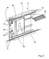
- FIG. 4 illustrates an appliance of another type, for example a thermostat 34, having two local adjustment knobs 36, distributed on the front face of the housing 24. On one of the small lateral faces are arranged control terminals 37 connected to the low current conductors 20. Indicators or other indicators 38 are visible on the front face. These adaptations are easy to make and do not affect the structure of the device which is that of the standard device.
- a range of devices is produced distributed in chutes by replacing the original housing with a housing adapted to these chutes.
- These adapted devices are housed flat in the chute, optionally transferring the control and display members to the front face.
- the connection of the conductors is preferably carried out before the complete insertion into the chute of the device.
- These devices can be used in trunking having only a lateral compartment of conductors or with a compartment arranged in the bottom of the chute, and it is possible to provide extensions when the dimensions of the chute are too large or a partial projection in the opposite case.
- the device can also be housed in an extension in the form of a lateral frame, associated or belonging to the chute so as to limit the section of the chute in the areas deprived of apparatus, the advantage of an absence of frontal projection being preserved.
- a frame or side box can also be provided for housing several modules at the same location of the chute.
- the invention is not limited to single-pole and neutral devices, but the size of the chute must correspond to that of the devices, and the invention extends to any variant.
Applications Claiming Priority (2)
| Application Number | Priority Date | Filing Date | Title |
|---|---|---|---|
| FR9005616 | 1990-05-02 | ||
| FR9005616A FR2661786B1 (fr) | 1990-05-02 | 1990-05-02 | Installation de distribution de l'electricite ayant des goulottes de logement de conducteurs et d'appareils electriques. |
Publications (2)
| Publication Number | Publication Date |
|---|---|
| EP0455563A1 true EP0455563A1 (de) | 1991-11-06 |
| EP0455563B1 EP0455563B1 (de) | 1995-06-28 |
Family
ID=9396315
Family Applications (1)
| Application Number | Title | Priority Date | Filing Date |
|---|---|---|---|
| EP19910420126 Expired - Lifetime EP0455563B1 (de) | 1990-05-02 | 1991-04-15 | Elektrische Verteilungsanlage mit Aufnahmeeinrichtungen für Leitungen und elektrische Geräte |
Country Status (4)
| Country | Link |
|---|---|
| EP (1) | EP0455563B1 (de) |
| DE (1) | DE69110755T2 (de) |
| ES (1) | ES2075947T3 (de) |
| FR (1) | FR2661786B1 (de) |
Cited By (6)
| Publication number | Priority date | Publication date | Assignee | Title |
|---|---|---|---|---|
| DE19511523A1 (de) * | 1994-12-22 | 1996-06-27 | Horst Wagner | Elektroinstallationssystem |
| WO1996030984A1 (de) * | 1995-03-28 | 1996-10-03 | Rittal-Werk Rudolf Loh Gmbh & Co. Kg | Sammelschienensystem |
| EP0957553A1 (de) * | 1998-05-11 | 1999-11-17 | GIRA GIERSIEPEN GmbH. & CO. KG | Kabelkanal |
| GB2352885A (en) * | 1999-07-29 | 2001-02-07 | Panduit Corp | Power outlet for multi-channel raceway |
| GB2421122A (en) * | 2004-12-13 | 2006-06-14 | Novar Ed & S Ltd | Multiple compartment cable trunk with cover and socket mounting box. |
| CN100426600C (zh) * | 2005-06-28 | 2008-10-15 | 正泰集团股份有限公司 | 可轻松改变插座位置的室内插座装置 |
Families Citing this family (3)
| Publication number | Priority date | Publication date | Assignee | Title |
|---|---|---|---|---|
| DE10325938B4 (de) * | 2003-06-07 | 2016-07-28 | Hager Electro Gmbh | Kleinverteiler |
| DE10325936A1 (de) * | 2003-06-07 | 2004-12-23 | Hager Electro Gmbh | Verteiler, insbesondere Kleinverteiler |
| DE102008026047A1 (de) * | 2008-01-26 | 2009-07-30 | Hager Electro Gmbh & Co. Kg | Verteilerkasten zum Einbau in eine Wandöffnung |
Citations (2)
| Publication number | Priority date | Publication date | Assignee | Title |
|---|---|---|---|---|
| US3566194A (en) * | 1969-09-02 | 1971-02-23 | Ite Imperial Corp | Shallow depth load center |
| FR2637131A1 (fr) * | 1988-09-26 | 1990-03-30 | Amp Inc | Assemblage a utiliser avec des conducteurs electriques |
-
1990
- 1990-05-02 FR FR9005616A patent/FR2661786B1/fr not_active Expired - Fee Related
-
1991
- 1991-04-15 EP EP19910420126 patent/EP0455563B1/de not_active Expired - Lifetime
- 1991-04-15 ES ES91420126T patent/ES2075947T3/es not_active Expired - Lifetime
- 1991-04-15 DE DE1991610755 patent/DE69110755T2/de not_active Expired - Fee Related
Patent Citations (2)
| Publication number | Priority date | Publication date | Assignee | Title |
|---|---|---|---|---|
| US3566194A (en) * | 1969-09-02 | 1971-02-23 | Ite Imperial Corp | Shallow depth load center |
| FR2637131A1 (fr) * | 1988-09-26 | 1990-03-30 | Amp Inc | Assemblage a utiliser avec des conducteurs electriques |
Cited By (9)
| Publication number | Priority date | Publication date | Assignee | Title |
|---|---|---|---|---|
| DE19511523A1 (de) * | 1994-12-22 | 1996-06-27 | Horst Wagner | Elektroinstallationssystem |
| WO1996030984A1 (de) * | 1995-03-28 | 1996-10-03 | Rittal-Werk Rudolf Loh Gmbh & Co. Kg | Sammelschienensystem |
| US5817977A (en) * | 1995-03-28 | 1998-10-06 | Rittal-Werk Rudolf Loh Gmbh & Co. Kg | Busbar system |
| EP0957553A1 (de) * | 1998-05-11 | 1999-11-17 | GIRA GIERSIEPEN GmbH. & CO. KG | Kabelkanal |
| GB2352885A (en) * | 1999-07-29 | 2001-02-07 | Panduit Corp | Power outlet for multi-channel raceway |
| GB2352885B (en) * | 1999-07-29 | 2003-03-26 | Panduit Corp | Power outlet for dividend channel raceway |
| GB2421122A (en) * | 2004-12-13 | 2006-06-14 | Novar Ed & S Ltd | Multiple compartment cable trunk with cover and socket mounting box. |
| GB2421122B (en) * | 2004-12-13 | 2009-07-22 | Novar Ed & S Ltd | Cable trunking system |
| CN100426600C (zh) * | 2005-06-28 | 2008-10-15 | 正泰集团股份有限公司 | 可轻松改变插座位置的室内插座装置 |
Also Published As
| Publication number | Publication date |
|---|---|
| DE69110755D1 (de) | 1995-08-03 |
| ES2075947T3 (es) | 1995-10-16 |
| FR2661786A1 (fr) | 1991-11-08 |
| DE69110755T2 (de) | 1996-02-22 |
| FR2661786B1 (fr) | 1992-07-10 |
| EP0455563B1 (de) | 1995-06-28 |
Similar Documents
| Publication | Publication Date | Title |
|---|---|---|
| EP0112232B1 (de) | Einspeisungs- oder Durchverbindungsanordnung für bausteinartig zusammengesetzte elektrische Apparate | |
| CA1331474C (en) | Residential load centre with busbar retaining means | |
| AU624800B2 (en) | Improvements relating to consumer units | |
| EP0455563B1 (de) | Elektrische Verteilungsanlage mit Aufnahmeeinrichtungen für Leitungen und elektrische Geräte | |
| EP0837534B1 (de) | Trag- und Stromeinspeisungsvorrichtung für ein elektrisches Gerät | |
| FR2535912A1 (fr) | Rail profile de fixation d'appareillage pour coffret ou tableau electrique de distribution a basse tension | |
| EP1329008B1 (de) | Hybrid-hochspannungsstation mit gegenüberliegenden abgängen, und gekapselten schalt- und-trennmodulen dafür | |
| FR2676586A1 (fr) | Dispositif d'assemblage mecanique et electrique de boitiers moules miniatures. | |
| EP0063970B1 (de) | Sammelschiene zur Speisung von modularer Apparatur eines elektrischen Kastens | |
| EP0425393A1 (de) | Vorrichtung zur Durchführung von Baugruppen zur Steuerung und Schutz elektrischer Niederspannungsschaltungen | |
| FR2703825A1 (fr) | Disjoncteur en boîtier moulé avec unité d'adaptation des transformateurs de courant. | |
| FR2646568A1 (en) | Electrical distribution panel equipped with isolators | |
| CA1331475C (en) | Adapter for mounting rail in a residential load centre | |
| US4931902A (en) | Bushbar barrier protective members | |
| US9263860B2 (en) | Power distribution system, and switchgear assembly, and mounting member therefor | |
| EP1146619A1 (de) | Rahmenschenkel für ein Rahmengestell, als Leiter zur Verteilung elektrischer Energie | |
| EP0270438B1 (de) | Elektrische Verteilungsanlage und Bestandteile | |
| JP7303819B2 (ja) | 回路遮断器ハウジング | |
| US3120592A (en) | Circuit breakers for panelboards | |
| GB2305008A (en) | Consumer units | |
| CA1118825A (fr) | Barriere isolante de separation d'une cellule de disjoncteurs a haute tension | |
| FR2735913A1 (fr) | Tableau prefabrique a moyenne tension a deux jeux de barres | |
| FR2539925A1 (fr) | Module de commutation haute-tension a trois voies, notamment pour poste de distribution publique d'un reseau d'alimentation en haute-tension suivant un schema dit en coupure d'artere, en boucle ou en double derivation | |
| FR2525829A1 (fr) | Poste compact de distribution d'energie electrique | |
| GB2305007A (en) | Consumer units |
Legal Events
| Date | Code | Title | Description |
|---|---|---|---|
| PUAI | Public reference made under article 153(3) epc to a published international application that has entered the european phase |
Free format text: ORIGINAL CODE: 0009012 |
|
| AK | Designated contracting states |
Kind code of ref document: A1 Designated state(s): BE CH DE ES GB IT LI SE |
|
| 17P | Request for examination filed |
Effective date: 19920415 |
|
| 17Q | First examination report despatched |
Effective date: 19940303 |
|
| RAP1 | Party data changed (applicant data changed or rights of an application transferred) |
Owner name: SCHNEIDER ELECTRIC SA |
|
| GRAA | (expected) grant |
Free format text: ORIGINAL CODE: 0009210 |
|
| AK | Designated contracting states |
Kind code of ref document: B1 Designated state(s): BE CH DE ES GB IT LI SE |
|
| REF | Corresponds to: |
Ref document number: 69110755 Country of ref document: DE Date of ref document: 19950803 |
|
| ITF | It: translation for a ep patent filed |
Owner name: EUROPATENT S.A.S. |
|
| REG | Reference to a national code |
Ref country code: ES Ref legal event code: FG2A Ref document number: 2075947 Country of ref document: ES Kind code of ref document: T3 |
|
| GBT | Gb: translation of ep patent filed (gb section 77(6)(a)/1977) |
Effective date: 19950918 |
|
| PLBE | No opposition filed within time limit |
Free format text: ORIGINAL CODE: 0009261 |
|
| STAA | Information on the status of an ep patent application or granted ep patent |
Free format text: STATUS: NO OPPOSITION FILED WITHIN TIME LIMIT |
|
| 26N | No opposition filed | ||
| PGFP | Annual fee paid to national office [announced via postgrant information from national office to epo] |
Ref country code: SE Payment date: 20010404 Year of fee payment: 11 |
|
| PGFP | Annual fee paid to national office [announced via postgrant information from national office to epo] |
Ref country code: GB Payment date: 20010411 Year of fee payment: 11 Ref country code: DE Payment date: 20010411 Year of fee payment: 11 |
|
| PGFP | Annual fee paid to national office [announced via postgrant information from national office to epo] |
Ref country code: CH Payment date: 20010412 Year of fee payment: 11 |
|
| PGFP | Annual fee paid to national office [announced via postgrant information from national office to epo] |
Ref country code: ES Payment date: 20010430 Year of fee payment: 11 |
|
| PGFP | Annual fee paid to national office [announced via postgrant information from national office to epo] |
Ref country code: BE Payment date: 20010621 Year of fee payment: 11 |
|
| REG | Reference to a national code |
Ref country code: GB Ref legal event code: IF02 |
|
| PG25 | Lapsed in a contracting state [announced via postgrant information from national office to epo] |
Ref country code: GB Free format text: LAPSE BECAUSE OF NON-PAYMENT OF DUE FEES Effective date: 20020415 |
|
| PG25 | Lapsed in a contracting state [announced via postgrant information from national office to epo] |
Ref country code: SE Free format text: LAPSE BECAUSE OF NON-PAYMENT OF DUE FEES Effective date: 20020416 Ref country code: ES Free format text: LAPSE BECAUSE OF NON-PAYMENT OF DUE FEES Effective date: 20020416 |
|
| PG25 | Lapsed in a contracting state [announced via postgrant information from national office to epo] |
Ref country code: LI Free format text: LAPSE BECAUSE OF NON-PAYMENT OF DUE FEES Effective date: 20020430 Ref country code: CH Free format text: LAPSE BECAUSE OF NON-PAYMENT OF DUE FEES Effective date: 20020430 Ref country code: BE Free format text: LAPSE BECAUSE OF NON-PAYMENT OF DUE FEES Effective date: 20020430 |
|
| PG25 | Lapsed in a contracting state [announced via postgrant information from national office to epo] |
Ref country code: DE Free format text: LAPSE BECAUSE OF NON-PAYMENT OF DUE FEES Effective date: 20021101 |
|
| EUG | Se: european patent has lapsed |
Ref document number: 91420126.4 |
|
| GBPC | Gb: european patent ceased through non-payment of renewal fee |
Effective date: 20020415 |
|
| REG | Reference to a national code |
Ref country code: CH Ref legal event code: PL |
|
| REG | Reference to a national code |
Ref country code: ES Ref legal event code: FD2A Effective date: 20030514 |
|
| PG25 | Lapsed in a contracting state [announced via postgrant information from national office to epo] |
Ref country code: IT Free format text: LAPSE BECAUSE OF NON-PAYMENT OF DUE FEES;WARNING: LAPSES OF ITALIAN PATENTS WITH EFFECTIVE DATE BEFORE 2007 MAY HAVE OCCURRED AT ANY TIME BEFORE 2007. THE CORRECT EFFECTIVE DATE MAY BE DIFFERENT FROM THE ONE RECORDED. Effective date: 20050415 |