EP0455557B1 - Arrangement of two ventilators for heating and/or air conditioning in a vehicle - Google Patents
Arrangement of two ventilators for heating and/or air conditioning in a vehicle Download PDFInfo
- Publication number
- EP0455557B1 EP0455557B1 EP91401157A EP91401157A EP0455557B1 EP 0455557 B1 EP0455557 B1 EP 0455557B1 EP 91401157 A EP91401157 A EP 91401157A EP 91401157 A EP91401157 A EP 91401157A EP 0455557 B1 EP0455557 B1 EP 0455557B1
- Authority
- EP
- European Patent Office
- Prior art keywords
- housing
- air
- installation according
- base wall
- rectangle
- Prior art date
- Legal status (The legal status is an assumption and is not a legal conclusion. Google has not performed a legal analysis and makes no representation as to the accuracy of the status listed.)
- Expired - Lifetime
Links
Images


Classifications
-
- B—PERFORMING OPERATIONS; TRANSPORTING
- B60—VEHICLES IN GENERAL
- B60H—ARRANGEMENTS OF HEATING, COOLING, VENTILATING OR OTHER AIR-TREATING DEVICES SPECIALLY ADAPTED FOR PASSENGER OR GOODS SPACES OF VEHICLES
- B60H1/00—Heating, cooling or ventilating [HVAC] devices
- B60H1/00457—Ventilation unit, e.g. combined with a radiator
Definitions
- the invention relates to a heating and / or air conditioning installation for a motor vehicle, comprising two air blowers - still called “fan units" - suitable for sending two streams of fresh air to the same heat exchanger inside. a distribution box.
- Such an installation is known for example from FR-A-2,623,757.
- This heat exchanger can be a simple heating radiator in the case of a vehicle heating appliance, or else an evaporator followed by a heating radiator, in the case of an air conditioning appliance.
- the fresh outside air first passes through the evaporator to be optionally cooled there and then the heating radiator to be optionally heated there.
- Installations of this type are usually used in certain categories of motor vehicles whose volume of the passenger compartment is large and therefore requires a higher flow of heating and / or air conditioning air than in the case of vehicles. classics.
- blowers by using two blowers, it is possible to use standard blowers, that is to say which find an application on vehicles of wide circulation, and which moreover have a small footprint.
- blowers have a drawback due to the fact that the blowers have a large manufacturing dispersion.
- blowers are driven by direct current electric motors and, for equal electrical voltage, two blowers can have very different air flow rates.
- the two air flows coming respectively from the two blowers are channeled by vanes which are perpendicular to the direction of introduction of the two flows and which are capable of directing them respectively towards two halves of the exchanger, usually half right and a left half.
- the object of the invention is in particular to remedy this drawback.
- the housing provides two inlet sections arranged opposite and suitable for being connected respectively to the two blowers to introduce the two flows into the housing.
- the two chambers defined therein can be in vertically superimposed relation, so that a first air flow is obtained which passes through the lower half of the exchanger and a second air flow which crosses the upper half of the exchanger.
- the housing is generally rectangular in shape and comprises a rectangular bottom wall and four side walls attached to the bottom wall, namely two longitudinal side walls and two transverse side walls, the two inlet sections being formed respectively in the two transverse walls, and the four side walls together defining a rectangular open face which constitutes the section of out of the housing.
- the general direction of the partition corresponds substantially to the direction of a diagonal of the rectangle.
- the two longitudinal side walls are arranged substantially horizontally and are of greater length than the transverse side walls which are then arranged substantially vertically. Therefore, the general direction of the partition is slightly inclined relative to the horizontal and allows a vertical superposition of the two chambers with the advantages mentioned above.
- the bottom wall comprises a central portion which extends in a general direction corresponding to a diagonal and which is extended by two curved ends terminating on two opposite sides of the rectangle, which advantageously correspond to the longitudinal side walls of the housing.
- the bottom wall comprises a single rectilinear part which extends in a direction close to that of a diagonal of the rectangle and which terminates on two opposite sides of the rectangle, which advantageously correspond to transverse walls of the housing.
- the housing partition advantageously comprises two rounded faces which connect to the bottom wall and which connect to each other along an edge, said rounded faces making it possible to change the direction of the two air flows in order to channel them towards the section Release.
- the bottom wall preferably comprises, in each of the two chambers, at least one deflector or distributor member to allow the change of the direction of flow of the flow.
- the bottom wall including the partition and its possible deflector members, is removable.
- the housing forms a housing suitable for directly receiving a heat exchanger, in particular an evaporator if the installation allows air conditioning.
- the housing it is particularly advantageous for the housing to include a conduit for discharging the condensates formed in the heat exchanger.
- the installation of the invention may also comprise, in a manner known per se, a mixing flap for ensuring the distribution of the air coming from the outlet section between a branch for transmitting fresh air and a branch for reheating of air.
- the mixing flap is advantageously mounted to pivot about an axis parallel to the direction of introduction of the two air flows into the housing.
- FIG. 1 shows a heating and / or air conditioning installation according to the prior art.
- This installation comprises a box 10 connected to two blowers 12 and 14, located respectively on the left and on the right side of a motor vehicle, respectively by means of two pipes 16 and 18 which do not necessarily have the same configuration.
- the housing 10 internally receives a heat exchanger 20 which can be, for example, an evaporator capable of ensuring the air conditioning of the passenger compartment of the motor vehicle.
- the blowers 12 and 14 are capable of sending two streams of fresh air, coming from outside the passenger compartment, inside the housing 10 which then channels these two streams through vanes 221, 241, 261 located on the left side of the housing and vanes 222, 242 and 262 located on the right side of the housing.
- These blades have generally curved shapes and have generatrices parallel to each other and perpendicular to the direction of flow of the flows F1 and F2 when they are introduced into the housing 10.
- blowers 12 and 14 can have very different flow rates, so that the flows F1 and F2 passing respectively through the left half and the right half of the exchanger 20 can have very different values, being able to be further increased by the fact that the lines 16 and 18 do not necessarily have the same configuration.
- This difference in flow rate causes a temperature difference at the outlet from the face of the exchanger 20.
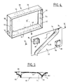
- FIGS. 2 and 3 partially show a heating and / or air conditioning installation according to the invention.
- This installation comprises a box 30 of generally parallelepipedal shape comprising a rectangular bottom wall 32 and four side walls attached to the bottom wall: two longitudinal side walls 36 and 38 parallel to one another and advantageously arranged horizontally, and two side walls transverse 40 and 42 parallel to each other and advantageously arranged vertically.
- the walls 36 and 38 are connected to the bottom wall 32 respectively by edges 44 and 46 which constitute the two long sides of the rectangle.
- the two short sides of the rectangle are materialized by edges 48 and 50 which are not directly attached to the walls 40 and 42.
- these walls respectively form two inlet sections 52 and 54 arranged opposite the one from the other ( Figure 3). These two sections each have a rectangular shape and extend over a height corresponding to that of the edges 48 and 50 and over a width less than the depth of the housing.
- the inlet sections 52 and 54 are suitable for being connected respectively to two blowers 56 and 58 situated respectively on the left and on the right side of the housing.
- the blowers 56 and 58 are suitable for introducing into the housing 30 two air flows in directions of introduction respectively F1 and F2, parallel and in opposite directions, and parallel to the bottom wall 32 of the housing (FIG. 2 ).
- the bottom wall 32 is provided with a partition 60 which protrudes towards the inside of the housing and which has a general direction close to the direction of introduction F1 and F2 of the two flows along the bottom wall 32
- the partition 60 comprises a central part 62 which extends in a general direction corresponding to a diagonal of the rectangle constituting the bottom wall 32, and which is extended by two curved ends 64 and 66 ending on two sides opposite of the rectangle, which correspond respectively to the longitudinal walls 36 and 38 of the housing ( Figure 2).
- the partition 62 thus forms inside the housing two separate chambers 68 and 70 (FIG. 2) supplied respectively by the blowers 56 and 58 and extending substantially over the same width in the general direction of introduction F1 and F2.
- These two chambers lead to an outlet section 72 (FIG. 3), of generally rectangular shape, which constitutes an open face of the housing 30 and which is limited by the four side walls 36, 38, 40 and 42.
- the outlet section 72 is suitable for accommodating a heat exchanger (not shown) capable of being traversed by the external air flows coming from the blowers 56 and 58 respectively. For this, the air flows must undergo a change of direction at right angles to the inside of the housing.
- the bottom wall 32 is advantageously removable and suitable for being applied against a wall 32 ′ which in fact constitutes the real bottom wall of the housing 30.
- the partition 60 comprises (FIG. 5) two rounded faces 74 and 76 which are connected to the bottom wall 32 and which are connected together along d 'an edge 78.
- two deflector or distributing members 80 and 82 are provided (FIGS. 2 to 5) located respectively on either side of the partition 60 in the region of the chambers 68 and 70. These two members also have a rounded shape and respectively provide passages 84 and 86, the section of which progressively widens from the entry to the exit. It will be understood that the air flow sent by the blower 56 flows along the bottom wall 32 and is deflected by the curved wall 74, while a part is deflected by the deflector member 80.
- the air flow sent by the blower 54 flows along the bottom wall 32 and is finally deflected by the curved wall 76 of the partition 60. Part of the flow is also deflected by the member. deflector 82.
- the wall 32 including the partition 60 and the deflector members 80 and 82, can be formed in one piece by molding a plastic material.
- the bottom wall 32 then comprises rectangular cutouts, for example a cutout 88 facing the deflector member 80 to allow demolding. The presence of these two cutouts is not a problem, since the bottom wall 32 is then attached to the wall 32 ′.
- a heat exchanger 90 which, in the example, is an evaporator of an air conditioning system.
- the housing 30 comprises, in the lower part, a pipe 92 suitable for allowing the evacuation of the condensates formed in the heat exchanger 90.
- the air flow F1 coming from the blower 56 passes essentially through the upper half of the exchanger 90, while the flow F2 coming from the blower 58 crosses the lower half of the exchanger. Even if the blowers 56 and 58 have different flow characteristics, and the air flows which pass respectively through the upper part and the lower part of the exchanger 90 are different, this does not constitute a disadvantage of the fact that these two flows are superimposed and that there is therefore no disparity between the right and left halves of the exchanger.
- the outlet section 72 of the housing 30 is connected to an inlet section 94 of another housing 96 of structure known per se. This housing 96 internally defines a branch 98 for transmitting fresh air and a branch 100 for reheating air.
- the latter has a U-shaped configuration and includes a heat exchanger 102 constituted by a heating radiator.
- the branch 100 comprises an inlet section 104 and an outlet section 106 which open respectively upstream and downstream of the branch 98.
- a mixing flap 108 pivotally mounted around an axis 100 makes it possible to vary the distribution between the branches 98 and 100 of the air which enters the housing 96 and, consequently, the temperature of the air which escapes from this housing. In the position of the flap shown in solid lines in Figure 6, all the air flow passes through the branch 100 and is thus heated. In the other extreme position shown in broken lines, the air flows only through branch 98 without being reheated. Of course, the flap 108 can take any intermediate position.
- the fresh or heated air arrives at a mixing zone 112 which is then capable of supplying, in a manner known per se, various distribution outlets inside the passenger compartment.
- the axis 110 of the flap 108 is horizontal and therefore parallel to the direction of introduction of the two flows F1 and F2 through the inlet sections of the housing. Consequently, if the flow rates of the air flows which pass respectively through the upper half and the lower half of the exchanger 90 are different, this difference is not a problem since it can be compensated by the flap 108.
- FIG. 7 shows another embodiment of the invention in which the partition 160 comprises a single rectilinear part which extends in a direction close to that of a diagonal of the rectangle and which ends in two opposite sides of the rectangle, which correspond to the transverse walls 40 and 42.
Description
L'invention concerne une installation de chauffage et/ou de climatisation pour véhicule automobile, comprenant deux pulseurs d'air -encore appelés "groupes motoventilateurs"-propres à envoyer deux flux d'air frais sur un même échangeur de chaleur à l'intérieur d'un boîtier de distribution. Une telle installation est connue par exemple de FR-A- 2.623.757.The invention relates to a heating and / or air conditioning installation for a motor vehicle, comprising two air blowers - still called "fan units" - suitable for sending two streams of fresh air to the same heat exchanger inside. a distribution box. Such an installation is known for example from FR-A-2,623,757.
Cet échangeur de chaleur peut être un simple radiateur de chauffage dans le cas d'un appareil de chauffage de véhicule, ou bien un évaporateur suivi d'un radiateur de chauffage, dans le cas d'un appareil de climatisation. En ce cas, l'air frais extérieur traverse d'abord l'évaporateur pour y être éventuellement refroidi et ensuite le radiateur de chauffage pour y être éventuellement réchauffé.This heat exchanger can be a simple heating radiator in the case of a vehicle heating appliance, or else an evaporator followed by a heating radiator, in the case of an air conditioning appliance. In this case, the fresh outside air first passes through the evaporator to be optionally cooled there and then the heating radiator to be optionally heated there.
On utilise habituellement des installations de ce genre dans certaines catégories de véhicules automobiles dont le volume de l'habitacle est important et nécessite, de ce fait, un débit d'air de chauffage et/ou de climatisation plus élevé que dans le cas des véhicules classiques.Installations of this type are usually used in certain categories of motor vehicles whose volume of the passenger compartment is large and therefore requires a higher flow of heating and / or air conditioning air than in the case of vehicles. classics.
En effet, il est apparu préférable d'utiliser deux pulseurs dont les débits s'additionnent, plutôt qu'un seul pulseur assurant le débit d'air élevé requis.Indeed, it has appeared preferable to use two blowers whose flows add up, rather than a single blower ensuring the high air flow required.
Pour offrir un tel débit d'air avec un seul pulseur, il faudrait concevoir un pulseur spécifique qui ne pourrait pas être utilisé sur les véhicules classiques qui serait particulièrement encombrant et en outre génèrerait des bruits de fonctionnement.To offer such an air flow with a single blower, it would be necessary to design a specific blower which could not be used on conventional vehicles which would be particularly bulky and furthermore generate operating noises.
Par contre, en faisant appel à deux pulseurs, on peut utiliser des pulseurs standards, c'est-à-dire trouvant une application sur des véhicules de grande diffusion, et qui de surcroît présentent un faible encombrement.On the other hand, by using two blowers, it is possible to use standard blowers, that is to say which find an application on vehicles of wide circulation, and which moreover have a small footprint.
Cependant, l'utilisation de deux pulseurs dans une même installation présente un inconvénient dû au fait que les pulseurs présentent une dispersion de fabrication importante.However, the use of two blowers in the same installation has a drawback due to the fact that the blowers have a large manufacturing dispersion.
Ces pulseurs sont animés par des moteurs électriques à courant continu et, à tension électrique égale, deux pulseurs peuvent avoir des débits d'air très différents.These blowers are driven by direct current electric motors and, for equal electrical voltage, two blowers can have very different air flow rates.
Il en résulte qu'il est impossible d'appareiller deux pulseurs pour qu'ils aient rigoureusement le même débit, si bien que le débit d'air qui traverse l'échangeur de chaleur n'est pas homogène sur toute sa surface.As a result, it is impossible to pair two blowers so that they have rigorously the same flow rate, so that the air flow which passes through the heat exchanger is not homogeneous over its entire surface.
En pratique, les deux flux d'air issus respectivement des deux pulseurs sont canalisés par des aubes qui sont perpendiculaires à la direction d'introduction des deux flux et qui sont propres à les diriger respectivement vers deux moitiés de l'échangeur, habituellement une moitié droite et une moitié gauche.In practice, the two air flows coming respectively from the two blowers are channeled by vanes which are perpendicular to the direction of introduction of the two flows and which are capable of directing them respectively towards two halves of the exchanger, usually half right and a left half.
Il en résulte alors que le débit d'air qui circule à travers l'une des moitiés n'est pas le même que celui qui circule à travers l'autre.As a result, the air flow which circulates through one of the halves is not the same as that which circulates through the other.
Cet inconvénient peut être en outre aggravé par le fait que les deux pulseurs sont généralement reliés au boîtier par l'intermédiaire de deux conduites qui n'ont pas nécessairement la même configuration et donc pas la même perte de charge.This drawback can be further aggravated by the fact that the two blowers are generally connected to the housing by means of two pipes which do not necessarily have the same configuration and therefore not the same pressure drop.
L'invention a notamment pour but de remédier à cet inconvénient.The object of the invention is in particular to remedy this drawback.
Elle propose, en conséquence, une installation du type défini en introduction, dans laquelle le boîtier ménage deux sections d'entrée disposées en vis-à-vis et propres à être reliées respectivement aux deux pulseurs pour introduire, dans le boîtier, les deux flux d'air suivant des directions d'introduction parallèles et de sens opposés, et parallèlement à une paroi de fond du boîtier, la paroi de fond étant munie d'une cloison de séparation qui fait saillie vers l'intérieur du boîtier et qui présente une direction générale proche de la direction d'introduction des deux flux le long de la paroi de fond, ce qui permet de définir deux chambres qui s'étendent sensiblement sur la même largeur dans ladite direction d'introduction et qui débouchent sur une section de sortie propre à être reliée à l'échangeur de chaleur.It therefore proposes an installation of the type defined in the introduction, in which the housing provides two inlet sections arranged opposite and suitable for being connected respectively to the two blowers to introduce the two flows into the housing. air in parallel directions of introduction and opposite directions, and parallel to a bottom wall of the housing, the bottom wall being provided with a partition wall which projects towards the inside of the housing and which has a general direction close to the direction of introduction of the two flows along the bottom wall, which makes it possible to define two chambers which extend substantially over the same width in said direction of introduction and which lead to an outlet section suitable for being connected to the heat exchanger.
De ce fait, on peut canaliser les deux flux d'air à l'intérieur du boîtier dans deux chambres adjacentes qui s'étendent sensiblement sur la même largeur dans la direction d'introduction des deux flux.Therefore, one can channel the two air flows inside the housing in two adjacent chambers which extend substantially over the same width in the direction of introduction of the two flows.
En disposant les deux sections d'entrée respectivement à droite et à gauche du boîtier, les deux chambres définies dans celui-ci peuvent être en relation superposée verticalement, si bien que l'on obtient un premier flux d'air qui traverse la moitié inférieure de l'échangeur et un second flux d'air qui traverse la moitié supérieure de l'échangeur.By arranging the two inlet sections respectively on the right and on the left of the housing, the two chambers defined therein can be in vertically superimposed relation, so that a first air flow is obtained which passes through the lower half of the exchanger and a second air flow which crosses the upper half of the exchanger.
Même si les débits de ces deux flux présentent une disparité importante, celle-ci n'est pas gênante car elle ne nuit pas à la répartition des deux flux respectivement du côté droit et du côté gauche de l'habitacle.Even if the flow rates of these two flows have a significant disparity, this is not a problem since it does not affect the distribution of the two flows respectively on the right side and on the left side of the passenger compartment.
Dans une forme de réalisation préférée de l'invention, le boîtier est de forme générale parallélépipédique et comprend une paroi de fond rectangulaire et quatre parois latérales rattachées à la paroi de fond, à savoir deux parois latérales longitudinales et deux parois latérales transversales, les deux sections d'entrée étant formées respectivement dans les deux parois transversales, et les quatre parois latérales définissant ensemble une face ouverte rectangulaire qui constitue la section de sortie du boîtier.In a preferred embodiment of the invention, the housing is generally rectangular in shape and comprises a rectangular bottom wall and four side walls attached to the bottom wall, namely two longitudinal side walls and two transverse side walls, the two inlet sections being formed respectively in the two transverse walls, and the four side walls together defining a rectangular open face which constitutes the section of out of the housing.
Avantageusement, la direction générale de la cloison correspond sensiblement à la direction d'une diagonale du rectangle.Advantageously, the general direction of the partition corresponds substantially to the direction of a diagonal of the rectangle.
Ainsi, il est tout particulièrement avantageux de prévoir que les deux parois latérales longitudinales soient disposées sensiblement à l'horizontale et soient de longueur plus grande que les parois latérales transversales qui sont alors disposées sensiblement à la verticale. De ce fait, la direction générale de la cloison est faiblement inclinée par rapport à l'horizontale et permet une superposition verticale des deux chambres avec les avantages mentionnés précédemment.Thus, it is very particularly advantageous to provide that the two longitudinal side walls are arranged substantially horizontally and are of greater length than the transverse side walls which are then arranged substantially vertically. Therefore, the general direction of the partition is slightly inclined relative to the horizontal and allows a vertical superposition of the two chambers with the advantages mentioned above.
Dans une des formes de réalisation de l'invention, la paroi de fond comprend une partie centrale qui s'étend dans une direction générale correspondant à une diagonale et qui se prolonge par deux extrémités incurvées aboutissant sur deux côtés opposés du rectangle, qui correspondent avantageusement aux parois latérales longitudinales du boîtier.In one of the embodiments of the invention, the bottom wall comprises a central portion which extends in a general direction corresponding to a diagonal and which is extended by two curved ends terminating on two opposite sides of the rectangle, which advantageously correspond to the longitudinal side walls of the housing.
Dans une autre forme de réalisation de l'invention, la paroi de fond comprend une partie rectiligne unique qui s'étend dans une direction proche de celle d'une diagonale du rectangle et qui aboutit sur deux côtés opposés du rectangle, qui correspondent avantageusement aux parois transversales du boîtier.In another embodiment of the invention, the bottom wall comprises a single rectilinear part which extends in a direction close to that of a diagonal of the rectangle and which terminates on two opposite sides of the rectangle, which advantageously correspond to transverse walls of the housing.
La cloison du boîtier comprend avantageusement deux faces arrondies qui se raccordent à la paroi de fond et qui se raccordent entre elles le long d'une arête, lesdites faces arrondies permettant de changer la direction des deux flux d'air pour les canaliser vers la section de sortie.The housing partition advantageously comprises two rounded faces which connect to the bottom wall and which connect to each other along an edge, said rounded faces making it possible to change the direction of the two air flows in order to channel them towards the section Release.
Pour faciliter cette canalisation, la paroi de fond comprend de préférence, dans chacune des deux chambres, au moins un organe déflecteur ou répartiteur pour permettre le changement de la direction d'écoulement du flux.To facilitate this channeling, the bottom wall preferably comprises, in each of the two chambers, at least one deflector or distributor member to allow the change of the direction of flow of the flow.
Avantageusement, la paroi de fond, y compris la cloison de séparation et ses organes déflecteurs éventuels, est amovible.Advantageously, the bottom wall, including the partition and its possible deflector members, is removable.
Avantageusement, le boîtier forme un logement propre à recevoir directement un échangeur de chaleur, en particulier un évaporateur si l'installation permet la climatisation. En ce cas, il est tout particulièrement avantageux que le boîtier comprenne un conduit pour l'évacuation des condensats formés dans l'échangeur de chaleur.Advantageously, the housing forms a housing suitable for directly receiving a heat exchanger, in particular an evaporator if the installation allows air conditioning. In this case, it is particularly advantageous for the housing to include a conduit for discharging the condensates formed in the heat exchanger.
L'installation de l'invention peut comprendre en outre, de manière en soi connue, un volet de mixage pour assurer la répartition de l'air issu de la section de sortie entre une branche de transmission d'air frais et une branche de réchauffage d'air. En ce cas, le volet de mixage est avantageusement monté à pivotement autour d'un axe parallèle à la direction d'introduction des deux flux d'air dans le boîtier.The installation of the invention may also comprise, in a manner known per se, a mixing flap for ensuring the distribution of the air coming from the outlet section between a branch for transmitting fresh air and a branch for reheating of air. In this case, the mixing flap is advantageously mounted to pivot about an axis parallel to the direction of introduction of the two air flows into the housing.
Dans la description qui suit, faite seulement à titre d'exemple, on se réfère aux dessins annexés, sur lesquels :
- la figure 1 est une vue schématique de dessus d'une installation de chauffage et/ou de climatisation à deux pulseurs d'air selon la technique antérieure;
- la figure 2 est une vue en élévation d'une partie d'une installation de chauffage et/ou de climatisation selon l'invention;
- la figure 3 est une vue en perspective du boîtier de l'installation de la figure 2;
- la figure 4 est une vue en perspective éclatée du boîtier de la figure 3;
- la figure 5 est une vue en coupe de la paroi de fond du boîtier selon la ligne V-V de la figure 4;
- la figure 6 est une vue partielle en coupe longitudinale d'une installation selon l'invention; et
- la figure 7 est une vue en élévation d'une partie d'une installation selon l'invention, dans une autre forme de réalisation.
- Figure 1 is a schematic top view of a heating and / or air conditioning system with two air blowers according to the prior art;
- Figure 2 is an elevational view of part of a heating and / or air conditioning installation according to the invention;
- Figure 3 is a perspective view of the housing of the installation of Figure 2;
- Figure 4 is an exploded perspective view of the housing of Figure 3;
- Figure 5 is a sectional view of the bottom wall of the housing along the line VV of Figure 4;
- Figure 6 is a partial view in longitudinal section of an installation according to the invention; and
- Figure 7 is an elevational view of part of an installation according to the invention, in another embodiment.
On se réfère tout d'abord à la figure 1 qui montre une installation de chauffage et/ou de climatisation selon la technique antérieure. Cette installation comprend un boîtier 10 relié à deux pulseurs 12 et 14, situés respectivement du côté gauche et du côté droit d'un véhicule automobile, respectivement par l'intermédiaire de deux conduites 16 et 18 qui n'ont pas nécessairement la même configuration. Le boîtier 10 reçoit intérieurement un échangeur de chaleur 20 qui peut être, par exemple, un évaporateur propre à assurer la climatisation de l'habitacle du véhicule automobile.Reference is first made to FIG. 1 which shows a heating and / or air conditioning installation according to the prior art. This installation comprises a
Les pulseurs 12 et 14 sont propres à envoyer deux flux d'air frais, provenant de l'extérieur de l'habitacle, à l'intérieur du boîtier 10 qui canalise ensuite ces deux flux grâce à des aubes 22₁, 24₁, 26₁ situées du côté gauche du boîtier et des aubes 22₂, 24₂ et 26₂ situées du côté droit du boîtier. Ces aubes ont des formes générales incurvées et possèdent des génératrices parallèles entre elles et perpendiculaires à la direction d'écoulement des flux F1 et F2 lors de leur introduction dans le boîtier 10.The
Du fait des dispersions de fabrication, les pulseurs 12 et 14 peuvent avoir des débits très différents, si bien que les flux F1 et F2 traversant respectivement la moitié gauche et la moitié droite de l'échangeur 20 peuvent avoir des valeurs très différentes, en pouvant être encore accrue par le fait que les conduites 16 et 18 n'ont pas nécessairement la même configuration. Cette différence de débit entraîne une différence de température à la sortie de la face de l'échangeur 20.Due to manufacturing dispersions, the
On se réfère maintenant aux figures 2 et 3 qui montrent en partie une installation de chauffage et/ou de climatisation selon l'invention.Reference is now made to FIGS. 2 and 3 which partially show a heating and / or air conditioning installation according to the invention.
Cette installation comprend un boîtier 30 de forme générale parallélépipédique comprenant une paroi de fond rectangulaire 32 et quatre parois latérales rattachées à la paroi de fond : deux parois latérales longitudinales 36 et 38 parallèles entre elles et avantageusement disposées à l'horizontale, et deux parois latérales transversales 40 et 42 parallèles entre elles et avantageusement disposées à la verticale. Les parois 36 et 38 se raccordent à la paroi de fond 32 respectivement par des arêtes 44 et 46 qui constituent les deux grands côtés du rectangle. Les deux petits côtés du rectangle sont matérialisés par des bords 48 et 50 qui ne sont pas rattachés directement aux parois 40 et 42. En effet, ces parois forment respectivement deux sections d'entrée 52 et 54 disposées en vis-à-vis l'une de l'autre (figure 3). Ces deux sections ont chacune une forme rectangulaire et s'étendent sur une hauteur correspondant à celle des bords 48 et 50 et sur une largeur inférieure à la profondeur du boîtier. Les sections d'entrée 52 et 54 sont propres à être reliées respectivement à deux pulseurs 56 et 58 situés respectivement du côté gauche et du côté droit du boîtier. Les pulseurs 56 et 58 sont propres à introduire, dans le boîtier 30, deux flux d'air suivant des directions d'introduction respectivement F1 et F2, parallèles et de sens opposés, et parallèlement à la paroi de fond 32 du boîtier (figure 2).This installation comprises a
La paroi de fond 32 est munie d'une cloison de séparation 60 qui fait saillie vers l'intérieur du boîtier et qui présente une direction générale proche de la direction d'introduction F1 et F2 des deux flux le long de la paroi de fond 32. Dans l'exemple, la cloison 60 comprend une partie centrale 62 qui s'étend dans une direction générale correspondant à une diagonale du rectangle constituant la paroi de fond 32, et qui se prolonge par deux extrémités incurvées 64 et 66 aboutissant sur deux côtés opposés du rectangle, qui correspondent respectivement aux parois longitudinales 36 et 38 du boîtier (figure 2). La cloison 62 forme ainsi à l'intérieur du boîtier deux chambres distinctes 68 et 70 (figure 2) alimentées respectivement par les pulseurs 56 et 58 et s'étendant sensiblement sur la même largeur dans la direction générale d'introduction F1 et F2. Ces deux chambres débouchent sur une section de sortie 72 (figure 3), de forme générale rectangulaire, qui constitue une face ouverte du boîtier 30 et qui est limitée par les quatre parois latérales 36, 38, 40 et 42.The
La section de sortie 72 est propre à accueillir un échangeur de chaleur (non représenté) propre à être traversé par les flux d'air extérieur issus respectivement des pulseurs 56 et 58. Pour cela, les flux d'air doivent subir un changement de direction à angle droit à l'intérieur du boîtier.The
Comme montré à la figure 4, la paroi de fond 32 est avantageusement amovible et propre à être appliquée contre une paroi 32′ qui constitue en fait la véritable paroi de fond du boîtier 30.As shown in FIG. 4, the
Pour faciliter le changement de direction des flux F1 et F2 à l'intérieur du boîtier, la cloison 60 comprend (figure 5) deux faces arrondies 74 et 76 qui se raccordent à la paroi de fond 32 et qui se raccordent entre elles le long d'une arête 78.To facilitate the change of direction of the flows F1 and F2 inside the housing, the
Pour faciliter le changement de direction des deux flux, il est prévu en outre deux organes déflecteurs ou répartiteurs 80 et 82 (figures 2 à 5) situés respectivement de part et d'autre de la cloison 60 dans la région des chambres 68 et 70. Ces deux organes ont également une forme arrondie et ménagent respectivement des passages 84 et 86 dont la section va progressivement en s'évasant depuis l'entrée jusqu'à la sortie. On comprendra que le flux d'air envoyé par le pulseur 56 s'écoule le long de la paroi de fond 32 et est dévié par la paroi incurvée 74, tandis qu'une partie est déviée par l'organe déflecteur 80.To facilitate the change of direction of the two flows, two deflector or distributing
De façon correspondante, le flux d'air envoyé par le pulseur 54 s'écoule le long de la paroi de fond 32 et est finalement dévié par la paroi incurvée 76 de la cloison 60. Une partie du flux est également déviée par l'organe déflecteur 82.Correspondingly, the air flow sent by the
Comme montré aux figures 4 et 5, la paroi 32, y compris la cloison 60 et les organes déflecteurs 80 et 82, peuvent être formés d'une seule pièce par moulage d'une matière plastique. La paroi de fond 32 comprend alors des découpes rectangulaires, par exemple une découpe 88 en regard de l'organe déflecteur 80 pour permettre le démoulage. La présence de ces deux découpes n'est pas gênante, étant donné que la paroi de fond 32 est ensuite rapportée sur la paroi 32′.As shown in Figures 4 and 5, the
On se réfère maintenant à la figure 6. Dans la section de sortie 72 du boîtier 30 est logé un échangeur de chaleur 90 qui, dans l'exemple, est un évaporateur d'une installation de climatisation. Le boîtier 30 comprend, en partie inférieure, un tuyau 92 propre à permettre l'évacuation des condensats formés dans l'échangeur de chaleur 90.Referring now to Figure 6. In the
Dans l'exemple, le flux d'air F1 provenant du pulseur 56 traverse pour l'essentiel la moitié supérieure de l'échangeur 90, tandis que le flux F2 provenant du pulseur 58 traverse la moitié inférieure de l'échangeur. Même si les pulseurs 56 et 58 ont des caractéristiques de débit différentes, et que les débits d'air qui traversent respectivement la partie supérieure et la partie inférieure de l'échangeur 90 sont différentes, ceci ne constitue pas un inconvénient du fait que ces deux flux sont superposés et qu'il n'existe donc pas de disparité entre les moitiés droite et les moitiés gauche de l'échangeur. Dans l'installation représentée à la figure 6, la section de sortie 72 du boîtier 30 se raccorde sur une section d'entrée 94 d'un autre boîtier 96 de structure en soi connue. Ce boîtier 96 définit intérieurement une branche 98 de transmission d'air frais et une branche 100 de réchauffage d'air. Cette dernière a une configuration en U et comprend un échangeur de chaleur 102 constitué par un radiateur de chauffage. La branche 100 comprend une section d'entrée 104 et une section de sortie 106 qui débouchent respectivement en amont et en aval de la branche 98. Un volet de mixage 108 monté à pivotement autour d'un axe 100 permet de faire varier la répartition entre les branches 98 et 100 de l'air qui entre dans le boîtier 96 et, par conséquent, la température de l'air qui s'échappe de ce boîtier. Dans la position du volet représentée en trait plein sur la figure 6, tout le débit d'air passe par la branche 100 et est ainsi réchauffé. Dans l'autre position extrême représentée en trait interrompu, l'air s'écoule uniquement par la branche 98 sans être réchauffé. Bien entendu, le volet 108 peut prendre toute position intermédiaire. L'air frais ou réchauffé parvient à une zone de mixage 112 qui est propre à alimenter ensuite, de manière en soi connue, différentes bouches de distribution à l'intérieur de l'habitacle. Dans l'exemple, l'axe 110 du volet 108 est horizontal et donc parallèle à la direction d'introduction des deux flux F1 et F2 par les sections d'entrée du boîtier. Par conséquent, si les débits des flux d'air qui traversent respectivement la moitié supérieure et la moitié inférieure de l'échangeur 90 sont différents, cette différence n'est pas gênante puisqu'elle peut être compensée par le volet 108.In the example, the air flow F1 coming from the
On se réfère maintenant à la figure 7 qui montre une autre forme de réalisation de l'invention dans laquelle la cloison 160 comprend une partie rectiligne unique qui s'étend dans une direction proche de celle d'une diagonale du rectangle et qui aboutit sur deux côtés opposés du rectangle, qui correspondent aux parois transversales 40 et 42.Reference is now made to FIG. 7 which shows another embodiment of the invention in which the
Claims (10)
- A heating and/or air conditioning installation for a motor vehicle, comprising two air fans (56, 58), adapted to deliver two respective streams of fresh air to a common heat exchanger (90) within a housing (30), characterised in that the housing (30) defines two inlet sections (52, 54), which are disposed facing each other and which are adapted to be connected respectively to the two fans, whereby to introduce the two air streams into the housing, in inlet directions (F1 and F2) which are parallel and opposed to each other, and parallel to a base wall (32) of the housing (30), and in that the base wall (32) is provided with a separating bulkhead (60) which projects into the housing (30) and which extends in a general direction close to the inlet direction of the two streams along the base wall (32), so as to define two chambers (68, 70) which extend over substantially the same width in the said inlet direction and which exhaust into an outlet section (72) which is adapted to be connected to the heat exchanger.
- An installation according to Claim 1, characterised in that the housing (30) is of generally paraellelepipedic shape and includes a rectangular base wall (32) and four side walls joined to the base wall, namely two longitudinal side walls (36, 38) and two transverse side walls (40, 42), in that the two inlet sections (52, 54) are defined respectively in the two transverse walls (40, 42), and in that the four side walls together define a rectangular open face (72) which constitutes the said outlet section of the housing.
- An installation according to Claim 1 or Claim 2, in which the base wall (32) is of generally rectangular shape, characterised in that the general direction of the bulkhead (60) corresponds substantially to the direction of a diagonal of the rectangle.
- An installation according to Claim 3, characterised in that the bulkhead (60) comprises a central portion (62) which extends in a general direction corresponding to a diagonal of the rectangle and which is extended by two incurved terminal portions (64, 66), which terminate on two opposed sides of the rectangle corresponding to the longitudinal walls (36, 38).
- An installation according to Claim 3, characterised in that the bulkhead (160) comprises a single rectilinear portion, which extends in a direction close to that of a diagonal of the rectangle and which terminates on two opposed sides of the rectangle corresponding to the transverse walls (36, 38) of the housing.
- An installation according to one of Claims 1 to 5, characterised in that the bulkhead (60) includes two rounded faces (74, 76), which are joined to the base wall and which are joined together along an edge (78), whereby to change the direction of the two streams.
- An installation according to one of Claims 1 to 6, characterised in that the base wall (32) comprises, in the region of each of the two chambers (68, 70), at least one splitter member (80, 82) which is adapted to change the direction of flow of the air stream.
- An installation according to one of Claims 1 to 7, characterised in that the base wall (32) is removable.
- An installation according to one of Claims 1 to 8, characterised in that the housing (30) defines a mounting adapted for directly receiving a heat exchanger (90), in particular an evaporator, and includes in that case a duct (92) for evacuation of the condensates.
- An installation according to one of Claims 1 to 9, further including a mixing valve (108) which is adapted to distribute the air delivered from the outlet section (72), between a fresh air transmission branch (98) and an air heating branch (100), characterised in that the valve (108) is pivotally mounted about an axis (110) parallel to the direction in which the two streams (F1 and F2) are introduced into the inlet sections (52, 54) of the housing (30).
Applications Claiming Priority (2)
| Application Number | Priority Date | Filing Date | Title |
|---|---|---|---|
| FR9005680 | 1990-05-04 | ||
| FR9005680A FR2661644B1 (en) | 1990-05-04 | 1990-05-04 | HEATING AND / OR AIR CONDITIONING SYSTEM WITH TWO AIR PULSES FOR A MOTOR VEHICLE. |
Publications (2)
| Publication Number | Publication Date |
|---|---|
| EP0455557A1 EP0455557A1 (en) | 1991-11-06 |
| EP0455557B1 true EP0455557B1 (en) | 1993-03-10 |
Family
ID=9396361
Family Applications (1)
| Application Number | Title | Priority Date | Filing Date |
|---|---|---|---|
| EP91401157A Expired - Lifetime EP0455557B1 (en) | 1990-05-04 | 1991-05-02 | Arrangement of two ventilators for heating and/or air conditioning in a vehicle |
Country Status (6)
| Country | Link |
|---|---|
| US (1) | US5135046A (en) |
| EP (1) | EP0455557B1 (en) |
| JP (1) | JPH05238242A (en) |
| DE (1) | DE69100039T2 (en) |
| ES (1) | ES2038528T3 (en) |
| FR (1) | FR2661644B1 (en) |
Families Citing this family (11)
| Publication number | Priority date | Publication date | Assignee | Title |
|---|---|---|---|---|
| US5277547A (en) * | 1991-05-18 | 1994-01-11 | Usui Kokusai Sangyo Kaisha Ltd. | Motor fan unit |
| US5528454A (en) * | 1994-12-29 | 1996-06-18 | Compuserve Incorporated | Cooling device for electronic components arranged in a vertical series and vertical series of electronic devices containing same |
| EP0930186B1 (en) * | 1997-08-11 | 2003-11-05 | Denso Corporation | Air conditioner for vehicles |
| FR2774035B1 (en) * | 1998-01-29 | 2000-03-31 | Valeo Climatisation | MOTOR VEHICLE HEATING AND / OR AIR CONDITIONING DEVICE WITH IMPROVED HEAT EXCHANGE MANAGEMENT |
| FR2796335B1 (en) * | 1999-07-12 | 2001-10-05 | Valeo Climatisation | HEATING SYSTEM, ESPECIALLY A TYPE OF AIR CONDITIONING HAVING A MIXING SHUTTER |
| US6564858B1 (en) * | 2000-07-17 | 2003-05-20 | Liebert Corporation | Overhead cooling system with selectively positioned paths of airflow |
| CZ302206B6 (en) * | 2004-11-19 | 2010-12-15 | Minib, S.R.O. | Air-conditioning trough with forced air passage |
| FR2947040B1 (en) * | 2009-06-23 | 2014-01-03 | Cinier Radiateurs | REVERSIBLE RADIATOR |
| US9308799B2 (en) * | 2011-03-29 | 2016-04-12 | Denso International America, Inc. | Variable evaporator outlet air pressure distribution |
| CN105980178B (en) * | 2014-09-01 | 2017-12-12 | 翰昂系统株式会社 | Heat pump for vehicle |
| CN107101424A (en) * | 2017-06-30 | 2017-08-29 | 广东美芝制冷设备有限公司 | Evaporator assemblies, mounted air conditioner system and vehicle |
Family Cites Families (18)
| Publication number | Priority date | Publication date | Assignee | Title |
|---|---|---|---|---|
| US1889895A (en) * | 1931-06-01 | 1932-12-06 | Buckeye Blower Company | Cross flow radiator |
| US1938801A (en) * | 1931-07-21 | 1933-12-12 | Maxim Silencer Co | Ventilating and air conditioning device |
| US1879802A (en) * | 1931-08-15 | 1932-09-27 | Buckeye Blower Company | Double radiator with means of expansion on radiators |
| US2008255A (en) * | 1933-11-16 | 1935-07-16 | Larkin Refrigerating Corp | Counter flow air conditioner |
| US2149382A (en) * | 1935-08-30 | 1939-03-07 | B F Sturtevant Co | Air distributor |
| US2184837A (en) * | 1938-06-09 | 1939-12-26 | B F Sturtevant Co | Heat exchange unit |
| US2496652A (en) * | 1948-03-03 | 1950-02-07 | John E Ahrens | Refrigeration unit |
| GB697261A (en) * | 1950-06-09 | 1953-09-16 | Paul Raymond Marchal | Improvements in air-distributing apparatus employing heat exchangers |
| GB740069A (en) * | 1953-07-02 | 1955-11-09 | Sulzer Ag | Apparatus for forming an air curtain |
| US2904316A (en) * | 1955-07-26 | 1959-09-15 | Union Stock Yard & Transit Co Chicago | Cold room cooler for meats and other perishable products |
| US2995906A (en) * | 1959-10-28 | 1961-08-15 | A R A Mfg Company | Compact cooling unit |
| US3236298A (en) * | 1962-04-19 | 1966-02-22 | Laing Vortex Inc | Heat exchangers |
| US3403725A (en) * | 1966-10-04 | 1968-10-01 | Trane Co | Axial flow fan arrangement for fan coil unit |
| US3519069A (en) * | 1968-06-03 | 1970-07-07 | Lee Robert Green | Heat exchanging apparatus |
| US3603380A (en) * | 1968-06-14 | 1971-09-07 | Sabastien S Corhanidis | Gas distribution system for effecting heat exchange |
| JPS57130815A (en) * | 1981-02-04 | 1982-08-13 | Nippon Denso Co Ltd | Air conditioner for automobiles |
| DE3520548A1 (en) * | 1985-06-07 | 1986-12-11 | Süddeutsche Kühlerfabrik Julius Fr. Behr GmbH & Co KG, 7000 Stuttgart | HEATING OR AIR CONDITIONING FOR MOTOR VEHICLES |
| DE3740132A1 (en) * | 1987-11-26 | 1989-06-08 | Daimler Benz Ag | VENTILATION DEVICE FOR THE INTERIOR OF A VEHICLE |
-
1990
- 1990-05-04 FR FR9005680A patent/FR2661644B1/en not_active Expired - Lifetime
-
1991
- 1991-05-02 DE DE9191401157T patent/DE69100039T2/en not_active Expired - Fee Related
- 1991-05-02 EP EP91401157A patent/EP0455557B1/en not_active Expired - Lifetime
- 1991-05-02 US US07/694,882 patent/US5135046A/en not_active Expired - Lifetime
- 1991-05-02 ES ES199191401157T patent/ES2038528T3/en not_active Expired - Lifetime
- 1991-05-07 JP JP3130263A patent/JPH05238242A/en active Pending
Also Published As
| Publication number | Publication date |
|---|---|
| DE69100039T2 (en) | 1993-06-17 |
| JPH05238242A (en) | 1993-09-17 |
| EP0455557A1 (en) | 1991-11-06 |
| ES2038528T3 (en) | 1993-07-16 |
| DE69100039D1 (en) | 1993-04-15 |
| FR2661644A1 (en) | 1991-11-08 |
| FR2661644B1 (en) | 1992-07-17 |
| US5135046A (en) | 1992-08-04 |
Similar Documents
| Publication | Publication Date | Title |
|---|---|---|
| EP1288031B2 (en) | Device for generating a temperature controlled air flow for the passenger compartment of a motor vehicle and heating and/or air conditioning apparatus with such a device | |
| EP0455557B1 (en) | Arrangement of two ventilators for heating and/or air conditioning in a vehicle | |
| FR2631896A1 (en) | DISTRIBUTION HOUSING FOR HEATING AND / OR AIR CONDITIONING DEVICE, PARTICULARLY FOR MOTOR VEHICLE | |
| FR2659603A1 (en) | DEVICE FOR HEATING AND VENTILATING THE INTERIOR OF A MOTOR VEHICLE. | |
| FR2735426A1 (en) | DEVICE FOR HEATING-VENTILATION AND / OR AIR CONDITIONING OF THE INTERIOR OF A MOTOR VEHICLE | |
| EP2889168B1 (en) | Heating, ventilation and/or air conditioning device | |
| EP3490826A1 (en) | Heating, ventilation and/or air conditioning device for a motor vehicle | |
| EP0968857A1 (en) | Vehicle heating and/or airconditioning housing with improved acoustic performances | |
| EP1514707B1 (en) | Improved air temperature control of a passenger cell heating and/or air conditioning device | |
| EP0289405A1 (en) | Heating and ventilation apparatus, especially for the passenger compartment of a motor vehicle | |
| FR2720693A1 (en) | Device for heating and / or ventilating the passenger compartment of a vehicle. | |
| FR2724901A1 (en) | DEVICE FOR SUPPORTING A DASHBOARD OF A MOTOR VEHICLE | |
| FR2728116A1 (en) | POWER REGULATOR EQUIPMENT FOR ELECTRIC MOTOR AND CENTRIFUGAL FAN EQUIPPED WITH SUCH EQUIPMENT | |
| FR2742383A1 (en) | Heater or air-conditioner for passenger space of motor vehicle | |
| FR2859579A1 (en) | DEVICE FOR SUPPORTING AN ELECTRIC MOTOR DRIVING A TURBINE, ESPECIALLY FOR AN APPARATUS FOR HEATING, VENTILATION AND / OR AIR CONDITIONING OF A MOTOR VEHICLE | |
| EP0466571A1 (en) | Air blowing device for the heating and ventilation installation of a vehicle | |
| EP1090785B1 (en) | Improved air handling housing for the interior of, in particular, a motor vehicle | |
| WO1999033677A2 (en) | Heating/air-conditioning device integrated in a motor vehicle instrument panel | |
| FR2614243A1 (en) | CASE OF MOLDED PLASTIC MATERIAL FOR HEATING AND VENTILATION DEVICE, PARTICULARLY FOR MOTOR VEHICLE AND METHOD FOR ASSEMBLING THE SAME. | |
| EP0467751A1 (en) | Ventilator for heating- and/or air-conditioning system for motor-vehicles and installation equipped with two ventilators of this kind | |
| EP3046784A1 (en) | Air conditioning device for a motor vehicle with dual stream and distributor of cold | |
| FR2783465A1 (en) | Vehicle heating/air conditioning system integrated into the vehicles instrument panel. | |
| EP1640196B1 (en) | Structural element of a vehicle passenger compartment comprising a selective air distribution module | |
| FR2728511A1 (en) | Heating and ventilation unit for mounting in motor vehicle | |
| WO2022207838A1 (en) | Device for thermal treatment of air for a vehicle with improved temperature management |
Legal Events
| Date | Code | Title | Description |
|---|---|---|---|
| PUAI | Public reference made under article 153(3) epc to a published international application that has entered the european phase |
Free format text: ORIGINAL CODE: 0009012 |
|
| AK | Designated contracting states |
Kind code of ref document: A1 Designated state(s): DE ES GB IT SE |
|
| 17P | Request for examination filed |
Effective date: 19920224 |
|
| 17Q | First examination report despatched |
Effective date: 19920728 |
|
| GRAA | (expected) grant |
Free format text: ORIGINAL CODE: 0009210 |
|
| AK | Designated contracting states |
Kind code of ref document: B1 Designated state(s): DE ES GB IT SE |
|
| REF | Corresponds to: |
Ref document number: 69100039 Country of ref document: DE Date of ref document: 19930415 |
|
| GBT | Gb: translation of ep patent filed (gb section 77(6)(a)/1977) |
Effective date: 19930324 |
|
| ITF | It: translation for a ep patent filed |
Owner name: SOCIETA' ITALIANA BREVETTI S.P.A. |
|
| REG | Reference to a national code |
Ref country code: ES Ref legal event code: FG2A Ref document number: 2038528 Country of ref document: ES Kind code of ref document: T3 |
|
| PLBE | No opposition filed within time limit |
Free format text: ORIGINAL CODE: 0009261 |
|
| STAA | Information on the status of an ep patent application or granted ep patent |
Free format text: STATUS: NO OPPOSITION FILED WITHIN TIME LIMIT |
|
| 26N | No opposition filed | ||
| PGFP | Annual fee paid to national office [announced via postgrant information from national office to epo] |
Ref country code: ES Payment date: 19940518 Year of fee payment: 4 |
|
| PGFP | Annual fee paid to national office [announced via postgrant information from national office to epo] |
Ref country code: SE Payment date: 19940519 Year of fee payment: 4 |
|
| ITTA | It: last paid annual fee | ||
| EAL | Se: european patent in force in sweden |
Ref document number: 91401157.2 |
|
| PG25 | Lapsed in a contracting state [announced via postgrant information from national office to epo] |
Ref country code: SE Effective date: 19950503 Ref country code: ES Free format text: LAPSE BECAUSE OF NON-PAYMENT OF DUE FEES Effective date: 19950503 |
|
| EUG | Se: european patent has lapsed |
Ref document number: 91401157.2 |
|
| REG | Reference to a national code |
Ref country code: ES Ref legal event code: FD2A Effective date: 19990201 |
|
| REG | Reference to a national code |
Ref country code: GB Ref legal event code: IF02 |
|
| PG25 | Lapsed in a contracting state [announced via postgrant information from national office to epo] |
Ref country code: IT Free format text: LAPSE BECAUSE OF NON-PAYMENT OF DUE FEES;WARNING: LAPSES OF ITALIAN PATENTS WITH EFFECTIVE DATE BEFORE 2007 MAY HAVE OCCURRED AT ANY TIME BEFORE 2007. THE CORRECT EFFECTIVE DATE MAY BE DIFFERENT FROM THE ONE RECORDED. Effective date: 20050502 |
|
| PGFP | Annual fee paid to national office [announced via postgrant information from national office to epo] |
Ref country code: DE Payment date: 20050510 Year of fee payment: 15 |
|
| PGFP | Annual fee paid to national office [announced via postgrant information from national office to epo] |
Ref country code: GB Payment date: 20060421 Year of fee payment: 16 |
|
| PG25 | Lapsed in a contracting state [announced via postgrant information from national office to epo] |
Ref country code: DE Free format text: LAPSE BECAUSE OF NON-PAYMENT OF DUE FEES Effective date: 20061201 |
|
| GBPC | Gb: european patent ceased through non-payment of renewal fee |
Effective date: 20070502 |
|
| PG25 | Lapsed in a contracting state [announced via postgrant information from national office to epo] |
Ref country code: GB Free format text: LAPSE BECAUSE OF NON-PAYMENT OF DUE FEES Effective date: 20070502 |