EP0455405A2 - A method and apparatus for scrambling/descrambling a video signal - Google Patents
A method and apparatus for scrambling/descrambling a video signal Download PDFInfo
- Publication number
- EP0455405A2 EP0455405A2 EP91303663A EP91303663A EP0455405A2 EP 0455405 A2 EP0455405 A2 EP 0455405A2 EP 91303663 A EP91303663 A EP 91303663A EP 91303663 A EP91303663 A EP 91303663A EP 0455405 A2 EP0455405 A2 EP 0455405A2
- Authority
- EP
- European Patent Office
- Prior art keywords
- signal
- video signal
- composite video
- converter
- initial data
- Prior art date
- Legal status (The legal status is an assumption and is not a legal conclusion. Google has not performed a legal analysis and makes no representation as to the accuracy of the status listed.)
- Granted
Links
- 238000000034 method Methods 0.000 title claims abstract description 12
- 239000002131 composite material Substances 0.000 claims abstract description 74
- 239000011159 matrix material Substances 0.000 claims abstract description 31
- 230000000295 complement effect Effects 0.000 claims abstract description 15
- 230000004044 response Effects 0.000 claims abstract description 11
- 230000001360 synchronised effect Effects 0.000 claims description 67
- ZMRUPTIKESYGQW-UHFFFAOYSA-N propranolol hydrochloride Chemical compound [H+].[Cl-].C1=CC=C2C(OCC(O)CNC(C)C)=CC=CC2=C1 ZMRUPTIKESYGQW-UHFFFAOYSA-N 0.000 claims description 2
- 230000003139 buffering effect Effects 0.000 claims 2
- 230000006866 deterioration Effects 0.000 abstract description 2
- 238000010276 construction Methods 0.000 description 12
- 230000015654 memory Effects 0.000 description 12
- 238000010586 diagram Methods 0.000 description 6
- 239000000284 extract Substances 0.000 description 3
- 238000005070 sampling Methods 0.000 description 3
- 238000007792 addition Methods 0.000 description 1
- 230000000593 degrading effect Effects 0.000 description 1
- 238000004519 manufacturing process Methods 0.000 description 1
- 238000012986 modification Methods 0.000 description 1
- 230000004048 modification Effects 0.000 description 1
- 238000006467 substitution reaction Methods 0.000 description 1
Images


Classifications
-
- H—ELECTRICITY
- H04—ELECTRIC COMMUNICATION TECHNIQUE
- H04N—PICTORIAL COMMUNICATION, e.g. TELEVISION
- H04N7/00—Television systems
- H04N7/16—Analogue secrecy systems; Analogue subscription systems
- H04N7/167—Systems rendering the television signal unintelligible and subsequently intelligible
- H04N7/169—Systems operating in the time domain of the television signal
- H04N7/1696—Systems operating in the time domain of the television signal by changing or reversing the order of active picture signal portions
-
- H—ELECTRICITY
- H04—ELECTRIC COMMUNICATION TECHNIQUE
- H04N—PICTORIAL COMMUNICATION, e.g. TELEVISION
- H04N7/00—Television systems
- H04N7/10—Adaptations for transmission by electrical cable
-
- H—ELECTRICITY
- H04—ELECTRIC COMMUNICATION TECHNIQUE
- H04N—PICTORIAL COMMUNICATION, e.g. TELEVISION
- H04N21/00—Selective content distribution, e.g. interactive television or video on demand [VOD]
- H04N21/20—Servers specifically adapted for the distribution of content, e.g. VOD servers; Operations thereof
- H04N21/23—Processing of content or additional data; Elementary server operations; Server middleware
- H04N21/234—Processing of video elementary streams, e.g. splicing of video streams, manipulating MPEG-4 scene graphs
- H04N21/2347—Processing of video elementary streams, e.g. splicing of video streams, manipulating MPEG-4 scene graphs involving video stream encryption
-
- H—ELECTRICITY
- H04—ELECTRIC COMMUNICATION TECHNIQUE
- H04N—PICTORIAL COMMUNICATION, e.g. TELEVISION
- H04N21/00—Selective content distribution, e.g. interactive television or video on demand [VOD]
- H04N21/40—Client devices specifically adapted for the reception of or interaction with content, e.g. set-top-box [STB]; Operations thereof
- H04N21/43—Processing of content or additional data, e.g. demultiplexing additional data from a digital video stream; Elementary client operations, e.g. monitoring of home network or synchronising decoder's clock; Client middleware
- H04N21/44—Processing of video elementary streams, e.g. splicing a video clip retrieved from local storage with an incoming video stream, rendering scenes according to MPEG-4 scene graphs
- H04N21/4405—Processing of video elementary streams, e.g. splicing a video clip retrieved from local storage with an incoming video stream, rendering scenes according to MPEG-4 scene graphs involving video stream decryption
-
- H—ELECTRICITY
- H04—ELECTRIC COMMUNICATION TECHNIQUE
- H04N—PICTORIAL COMMUNICATION, e.g. TELEVISION
- H04N7/00—Television systems
- H04N7/16—Analogue secrecy systems; Analogue subscription systems
- H04N7/167—Systems rendering the television signal unintelligible and subsequently intelligible
-
- H—ELECTRICITY
- H04—ELECTRIC COMMUNICATION TECHNIQUE
- H04N—PICTORIAL COMMUNICATION, e.g. TELEVISION
- H04N7/00—Television systems
- H04N7/16—Analogue secrecy systems; Analogue subscription systems
- H04N7/167—Systems rendering the television signal unintelligible and subsequently intelligible
- H04N7/1675—Providing digital key or authorisation information for generation or regeneration of the scrambling sequence
Definitions
- the present invention relates to a method and apparatus for scrmabling and descrmbling a composite video signal, and more particularly to a method and an apparatus for bit-scrambling and again bit-descrambling a digital signal into which the composite video signal is converted thereby.
- the descrambler employed in the above-mentioned conventional line rotation system is shown in Fig. 1.
- the descrambler comprises an A/D converter 1 adapted to convert a composite video signal Vin inputted therein into 8 bit digital signals; two line memories 2 and 3 adapted to store the digital signals from said converter 1 alternately; a synchronous divider 4 adapted to divide said composite video signal Vin inputted therein into a horizontal synchronous signal H sync and a vertical synchronous signal V sync ; a clock generator 5 adapted to generate a sampling clock in response to said horizontal synchronous signal H sync from said synchronous divider 4 to apply said sampling clock to said A/D converter 1; a D/A converter 6 adapted to receive and convert the digital signals from said line memories 2 and 3 into an analog signal and to receive the sampling clock from said clock generator 5 ; a data slicer 7 adapted to extract from said composite video signal Vin initial data coded during a vertical blanking interval VBI thereof every each field thereof in order togenerate random numbers ;
- the A/D converter 1 upon receiving a scrambled composite video signal Vin, the A/D converter 1 converts it into 8 bit digital signals and sends the digital signals out to the line memories 2 and 3 alternately.
- the line memories 2 and 3 which receive the 8 bit digital signals alternately store them alternately in response to address signals from the address generator 11 and send said stored digital signals out to the D/A converter 6.
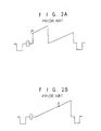
- the D/A converter 6 converts the received digital signals into an analog signal and generates a descrambled composite video signal Vout which is the same as the original composite video signal, as shown in Fig. 2B.
- address values for the line memories 2 and 3 correspond to a point P shown in Fig. 2B.
- a signal of waveform shown in Fig. 2A is scrambled about the point P corresponding to the address values. Accordingly, if a 10 bit random number generator in the scrambler(not shown) which is the same as the 10 bit random number generator 10 generates address values corresponding to the point P on each line randomly, an image from such scrambled video signal can not be recognized at all, like a noise image on screen.
- the above-mentioned random number generator of the scrambler as a transmitter transmits the scrambled composite video signal carried with initial data coded during the vertical blanking interval thereof every each field thereof. Accordingly, the data slicer 7 receives the scrambled composite video signal Vin and extracts the coded initial data which is in turn stored into the data RAM 8.
- the microprocessor 9 decodes the coded initial data stored in the data RAM 8 and supplies it to the 10 bit random number generator 10 as a control signal to control it. Therefore, the value of the point P generated in the scrambler as a transmitter is read precisely by the descrambler as a receiver.
- the scrambler as a transmitter and the descrambler as a receiber have the same construction including the 10 bit random number generator 10 so that if initial data values provided for each field are the same in both devices, namely, values of the point P generated at each horizontal scanning line are the same in both devices.
- the generated value for the point P is supplied to the address generator 11 which in turn supply address signals to the line memories 2 and 3 in order to read a data signal stored in the line memories 2 and 3 as shown in Fig. 2A, as a data signal as shown in Fig. 2B.
- the reason why two line memories 2 and 3 are used is to perform read and write operations on alternate horizontal lines alternately.
- the A/D converter 1 and the D/A converter 6 are intended for use of 8 bits and sample of 1024 per horizontal line(10 address lines), although nonlimited thereto.
- an apparatus for scrambling a video signal comprising an A/D converter for receiving a composite video signal to be bit-scrambled from an external equipment and converting the composite video sinal into a digital signal for bit-scrambling ; a multiplexing means for inputting the digital signal from said A/D converter and multiplexing the digital signal in response to an external select signal ; a D/A converter for receiving the multiplexed digital signal from said multiplexing means and converting the multiplexed digital signal into an analog signal; a synchronous divider for receiving said composite video signal and dividing the composite video signal into a vertical synchronous signal and a horizontal synchronous signal ; a clock generator for receiving the horizontal synchronous signal from said synchronous divider to generate a clock signal and supplying the clock signal to said A/D converter and said D/A converter ; an initial data generating means for receiving said composite video signal, extracting from said composite video signal initial data coded during a vertical blanking interval thereof every
- an apparatus for descrambling a video signal comprising an A/D converter for receiving a scrambled composite video signal to be descrambled and converting the composite video singal into a digital signal for descrambling ; a multiplexing means for inputting the digital signal from said A/D converter and multiplexing the digital signal in response to an external select signal ; a D/A converter for receiving the multiplexed digital signal from said multiplexing means and converting the multiplexed digital signal into an analog signal; a synchronous divider for receiving said composite video signal and dividing the composite video signal into a vertical synchronous signal and a horizontal synchronous signal ; a clock generator for receiving the horizontal synchronous signal from said synchronous divider to generate a clock signal and supplying the clock signal to said A/D converter and said D/A converter; an initial data generating means for receiving said composite video signal, extracting from said composite video signal initial data coded during a vertical blanking interval thereof every each field thereof, and
- a method of scrambling/descrambling a video signal comprising the steps of; converting a composite video signal into digital signals of a predetermined bit number and multiplying the digital signals by a transform matrix of a predetermined format to bit-scramble them; converting said bit-scrambled digital signals to an analog signal and transmitting the analog-converted signal to a user station; re-converting said analog-converted signal into digital signals of said predetermined bit number and multiplying the digital signals by alternative transform matrix of the reverse of said predetermined format to descramble them; and converting said descrambled digital signals to an original composite video signal.
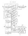
- a scrambler in accordance with an embodiment of the present invention is shown to comprise an A/D converter 1 which receives a composite video signal Vin from an external equipment and converts the composite video signal into 8 bit digital signals A0-A7. Also, the scrambler comprises a synchronous divider 4, a clock generator 5, a multiplexing means 100, a D/A converter 6, a horizontal blanking interval detector 13, an initial data generating means 200, a 3 bit random number generator 12 and an AND logic operating means 300.
- the synchronous divider 4 receives the composite video signal Vin from the external equipment and divides the composite video signal into a vertical synchronous signal V sync and a horizontal synchronous signal H sync which each is to be sent out to the 3 bit random number generator 12, and the clock generator 5 and the horizontal blanking interval detector 13.
- the clock generator 5 receives the horizontal synchronous signal H sync from the synchronous divider 4 to generate a clock signal and supplies the clock signal to the A/D converter 1 and D/A converter 6.
- the multiplexing means 100 comprises 8 8 ⁇ 1 multiplexers 21 through 28 which input simultaneously the 8 bit digital signals A0-A7 from the A/D converter 1. Each of the 8 ⁇ 1 multiplexers 21 through 28 outputs an 1-bit digital signal Y0-Y7 of the 8 bit digital signals A0-A7 to the D/A converter 6 in response to a 3 bit external select signal SEL from the AND logic operating means 300.
- the D/A converter 6 receives the 1 bit digital signal from each of the 8 ⁇ 1 multiplexers 21 through 28, the total 8 bit digital signals and converts the 8 bit digital signals into an scrambled analog signal.
- the horizontal blanking interval detector 13 detects a horizontal blanking interval from the horizontal synchronous signal from the synchronous divider 4, so that it outputs a "low” signal during the detected horizontal blanking interval while a "high” signal during the remaining interval.
- the initial data generating means 200 receives the composite video signal Vin from the external equipment, extracts from the composite video signal Vin initial data coded during a vertical blanking interval thereof every each field thereof and decodes the extracted coded initial data. Then, the decoded initial data from the initial data generating means 200 is sent out to the 3 bit random number generator 12.
- the 3 bit random number generator 12 Upon receiving the vertical synchronous signal V sync from the synchronous divider 4 and the decoded initial data from the initial data generating means 200, the 3 bit random number generator 12 generates 3 bit random numbers.
- the AND logic operating means 300 comprises 3 AND gates 14 through 16 which each has its one input terminal receiving 3 bit signals S1-S3 from the 3 bit random number generator 12 and its other input terminal receiving an output signal from the horizontal blanking interval detector 13. An output terminal of each of the AND gates 14 through 16 is coupled in common to the 8 ⁇ 1 multiplexers 21 through 28 to apply the external select signal SEL.
- the initial data generating means 200 comprises a data slicer 7 for extracting from the composite video signal Vin the initial data coded during the vertical blanking interval thereof every each field thereof, a data RAM 8 for storing the coded initial data from the data slicer 7, and a microprocessor 9 for decoding the coded initial data stored in the data RAM 8 and sending the decoded initial data out to the 3 bit random number generator 12.
- Fig. 4 is a block diagram showing partially a construction of an embodiment of a descrambler according to the present invention.
- This drawing is identical to the Fig. 3, except that there is shown a 2′S complement converter 17 connected between the output stage of the 3 bit random number generator 12 and the one input stage of AND gates 14 through 16 in the AND logic operating means 300.
- 3 bit complement signals S1′- S3′ on the 3 bit signals S1-S3 from the 3 bit random number generator 12 are received at the one input stage of AND gates 14 through 16, differently from the scrambler of the present invention.
- the construction of the descrambler in Fig.4 is identical to that of the scrambler in Fig. 3, but that it comprises the 2′S complement converter 17 connected between the output stage of the 3 bit random number generator 12 and the one input stage of AND gates 14 through 16 in the AND logic operating means 300.
- the 2′S complement converter 17 performs complementing on the 3 bit signals S1-S3 from the 3 bit random number generator.
- the 3 bit complement signals S1′- S3′ 12 on the 3 bit signals S1-S3 are sent out to the one input stage of AND gates 14 through 16, thereby allowing the external select signal SEL of the 2′S complement from the AND gates 14 through 16 in the AND logic operating means 300 to be applied to the multiplexing means 100.
- the 8 bit digital signals from the A/D converter 1 are inputted by the 8 8 ⁇ 1 multiplexers 21 through 28 simultaneously.
- each of the 8 ⁇ 1 multiplexers 21 through 28 outputs the 1 bit digital signal of the 8 bit digital signals to the D/A converter 6 in response to the 3 bit exteranl select signal SEL from the AND logic operating means 300.
- D/A converter 6 receives the 1 bit digital signal from each of the 8 ⁇ 1 multiplexers 21 through 28, the total 8 bit digital signals and converts the 8 bit digital signals into the scrambled analog signal. As a result, the scrambled analog signal can be outputted from the D/A converter 6.
- the synchronous divider 4 receives the composite video signal Vin from the external equipment, together with the A/D converter 1, and divides the composite video signal into vertical synchronous signal V sync and horizontal synchronous signal H which then is sent out to the clock generator 5 and the horizontal blanking interval detector 13.
- the clock generator 5 Upon receiving the horizontal synchronous signal H sync from the synchronous divider 4, the clock generator 5 generates a clock signal and applies it to the A/D converter 1 and the D/A convetere 6.
- the horizontal blanking interval detector 13 detects the horizontal blanking interval from the horizontal synchronous signal and applies a low signal to the other input terminals of respective AND gates 14 to 16 in the AND logic operating means 300 during the horizontal blanking interval. This is for the purpose of maintaining all outputs of the AND logic operating means 300 at low level state during the horizontal blanking interval, because this interval contains the horizontal synchronous signal, a color burst signal, a front porch and a back porch and needs no scrambling.
- the data slicer 7 in the initial data generating means 200 receives the composite video signal Vin which also is applied to the A/D converter 1 and the synchronous divider 4 and extracts from the composite video signal Vin the initial data coded during the vertical blanking interval thereof every each field thereof in order to store it into the data RAM 8.
- the microprocessor 9 decodes the coded initial data stored in the data RAM 8 and send the decoded initial data out to the 3 bit random number generator 12.
- the 3 bit random number generator 12 outputs 3 bit random numbers in response to the inputted initial data and the inputted vertical synchronous signal V sync from the synchronous divider 4.
- AND gates 14 to 16 in the AND logic operating means 300 receive 3 bit signals S1 to S3 as respective one input signals, respectively, and also receive an output signal from the horizontal blanking interval detector 13 as a common other input signal.
- the AND gates S1 to S3 AND logic operate the inputted signals and output 3 bit signals to the multiplexing means 100 as an external select signal, respectively.
- the following table 1 shows a transform matrix format when a composite video signal is converted into 8 bit digital signals.
- the procedure that the multiplexing means 100 is bit-scrambling digital signals from the A/D converter 1 in response to the external select signal SEL from the AND logic operating means 300 can be defined by the following transform matrix equation 1 : where, n is a random positive integer including zero, a is a bit number of the A/D converted composite video signal, j is a positive integer from 1 to a , and Ra(j+n) is the remainder when j+n was divided by a (optionally, a when the remainder is zero).
- transform matrix format tables 2 through 4 Several examples obtained by applying the matrix equation 1 to the transform matrix format table 1 can be expressed as transform matrix format tables 2 through 4 as follows:
- the table 3 shows a transform matrix format of where the random positive integer "n" in the matrix equation 1 is 3.
- the table 4 shows a transform matrix format of the descrambled state where the random positive integer in the matrix equation(1) is 3.
- the external select signal SEL can be obtained by the signals outputted from the 3 bit random number generator 12 and then complemented by the 2′S complement converter 17 as shown in Fig. 4, thus the matrix format of the digitalized composite video signal can be expressed as
- the table 4 can be obtained by substituting the above equations for the matrix equation (1).
- the first term of the scrambled matrix format table 3 can be expressed as :
- the fourth term of the descrambled matrix format table 4 can be expressed as:
- the scrambler as a transmitter generally transmits the scrambled composite video signal carried with initial data coded during the vertical blanking intervla thereof every each field thereof for preventing the non-subscriber from descrambling the video signal.
- the coded initial data is extracted by the data slicer 7 in the initial data generating means 200, stored in the data RAM 8, then decoded by the microprocessor 9.
- the decoded initial data is sent out to the 3 bit random number generator 12 every frame as a signal for controlling the 3 bit random number generator 12.
- non-subscriber who is not notified of information about the coded initial data can not descramble the scrambled video signal because he does not recognize the contents of the 3 bit signals S1-S3 from the 3 bit random number generator 12.
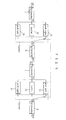
- the scrambler and the descrambler can have such constructions as shown in Fig. 5, in consideration of cases of ⁇ 0, ⁇ 1, ⁇ ⁇ .
- the 8 8 ⁇ 1 multiplexers 21 through 28 in Fig. 3 can be replaced by a buffer 32 in Fig. 5A, also in case of ⁇ 1, the multiplexers 21 through 28 can be replaced by a first shift register 31 shifting digital signal to the right, 1 bit, and in case of ⁇ ⁇ , the multiplexers 21 through 28 can be replaced by a second shift register 33 shifting digital signal to the left, 1 bit.
- the scrambler and the descrambler in accordance with the present invention can provide advantages as follows: First, they can cost down because there is no need to provide the two line memories which have been obliged to provide for the conventional apparatus; Second, they can prevent the image quality from being degraded because the cutting at the random point of the horizontal scanning line for scrambling does not need.
Abstract
Description
- The present invention relates to a method and apparatus for scrmabling and descrmbling a composite video signal, and more particularly to a method and an apparatus for bit-scrambling and again bit-descrambling a digital signal into which the composite video signal is converted thereby.
- There have been various systems for scrambling a composite video signal to prohibit illegally watching TV which is supplied by commercialized system. Among them, there has been used the most generally a line rotation system wherein the scrambled composite video signal is re-scrambled to be descrambled to be the original composite signal. Accordingly, operation principles of a scrambler and a descrambler are basically the same, and thus the operation principle of the descrambler will be described hereinafter only.
- The descrambler employed in the above-mentioned conventional line rotation system is shown in Fig. 1. As shown in the drawing, the descrambler comprises an A/
D converter 1 adapted to convert a composite video signal Vin inputted therein into 8 bit digital signals; twoline memories converter 1 alternately; asynchronous divider 4 adapted to divide said composite video signal Vin inputted therein into a horizontal synchronous signal Hsync and a vertical synchronous signal Vsync ; aclock generator 5 adapted to generate a sampling clock in response to said horizontal synchronous signal Hsync from saidsynchronous divider 4 to apply said sampling clock to said A/D converter 1; a D/A converter 6 adapted to receive and convert the digital signals from saidline memories clock generator 5 ; adata slicer 7 adapted to extract from said composite video signal Vin initial data coded during a vertical blanking interval VBI thereof every each field thereof in order togenerate random numbers ; adata RAM 8 adapted to store the coded initial data from saiddate slicer 7 ; amicroprocessor 9 adapted to decode said coded initial data stored in saiddata RAM 8 ; a 10 bitrandom number generator 10 adapted to receive said vertical synchronous signal Vsync from saidsynchronous divider 4 and the decoded initial data from saidmicroprocessor 9 and generate 10 bit random numbers ; and anaddress generator 11 adapted to receive output signals from said 10 bitrandom number generator 10 and apply address signals to theline memories - The operation of the descrambler with the above-mentioned construction will now be described.
- As shown in Fig. 2A, upon receiving a scrambled composite video signal Vin, the A/
D converter 1 converts it into 8 bit digital signals and sends the digital signals out to theline memories line memories address generator 11 and send said stored digital signals out to the D/A converter 6. The D/A converter 6 converts the received digital signals into an analog signal and generates a descrambled composite video signal Vout which is the same as the original composite video signal, as shown in Fig. 2B. - It is noted that address values for the
line memories - A signal of waveform shown in Fig. 2A is scrambled about the point P corresponding to the address values. Accordingly, if a 10 bit random number generator in the scrambler(not shown) which is the same as the 10 bit
random number generator 10 generates address values corresponding to the point P on each line randomly, an image from such scrambled video signal can not be recognized at all, like a noise image on screen. - On the other hand, the above-mentioned random number generator of the scrambler as a transmitter transmits the scrambled composite video signal carried with initial data coded during the vertical blanking interval thereof every each field thereof. Accordingly, the
data slicer 7 receives the scrambled composite video signal Vin and extracts the coded initial data which is in turn stored into thedata RAM 8. Themicroprocessor 9 decodes the coded initial data stored in thedata RAM 8 and supplies it to the 10 bitrandom number generator 10 as a control signal to control it. Therefore, the value of the point P generated in the scrambler as a transmitter is read precisely by the descrambler as a receiver. This is possible because the scrambler as a transmitter and the descrambler as a receiber have the same construction including the 10 bitrandom number generator 10 so that if initial data values provided for each field are the same in both devices, namely, values of the point P generated at each horizontal scanning line are the same in both devices. The generated value for the point P is supplied to theaddress generator 11 which in turn supply address signals to theline memories line memories line memories D converter 1 and the D/A converter 6 are intended for use of 8 bits and sample of 1024 per horizontal line(10 address lines), although nonlimited thereto. - In the above conventional construction, however, it the address value for the point P is generated by the random number generator, as above-mentioned, a certain point during the video signal interval corresponding to the point P is cut out and then the composite video signal is scrambled about the point P in a line rotation manner. At the cut part of the video signal, high frequency component to be noise is generated. As a result, it results in degrading image quality at the cut part. In addition, there is a disadvantage of expensive manufacture cost which is coused by the use of expensive two line memories. Furthermore, it can not prohibit the non-subscribers from watching illegally, because the composite video signal is simply scrambled by using two line memories.
- Therefore, it is an object of the present invention to provide a method and apparatus for scrambling and descrambling a digitalized composite video signal by using a transform matrix. It is another object of the present invention to provide a method and apparatus for scrambling and descrambling the digitalized composite video signal which is capable of avoiding any deterioration of the image quality, increase of cost, and illegally watching of non-subscribers.
- In accordance with one aspect of the present invention, there is provided an apparatus for scrambling a video signal comprising an A/D converter for receiving a composite video signal to be bit-scrambled from an external equipment and converting the composite video sinal into a digital signal for bit-scrambling ; a multiplexing means for inputting the digital signal from said A/D converter and multiplexing the digital signal in response to an external select signal ; a D/A converter for receiving the multiplexed digital signal from said multiplexing means and converting the multiplexed digital signal into an analog signal; a synchronous divider for receiving said composite video signal and dividing the composite video signal into a vertical synchronous signal and a horizontal synchronous signal ; a clock generator for receiving the horizontal synchronous signal from said synchronous divider to generate a clock signal and supplying the clock signal to said A/D converter and said D/A converter ; an initial data generating means for receiving said composite video signal, extracting from said composite video signal initial data coded during a vertical blanking interval thereof every each field thereof, and decoding the extracted coded initial data; a horizontal blanking interval detector for receiving the horizontal synchronous signal from said synchronous divider, detecting a horizontal blanking interval from said horizontal synchronous signal, and outputting a low signal during the detected horizontal blanking interval ; a random number generator for generating random numbers of a predetermined bit number, upon receiving the vertical synchronous signal from said synchronous divider and the decoded initial data from said initial data generating means ; and an AND logic operating means including a plurality of AND gates which each has its one input terminal for receiving each bit signal from said random number generator, its other input terminal for receiving an output signal from said horizontal blanking interval detector, its output terminal coupled in common to said multiplexing means for applying said external select signal.
- In accordance with another aspect of the present invention, there is provided an apparatus for descrambling a video signal comprising an A/D converter for receiving a scrambled composite video signal to be descrambled and converting the composite video singal into a digital signal for descrambling ; a multiplexing means for inputting the digital signal from said A/D converter and multiplexing the digital signal in response to an external select signal ; a D/A converter for receiving the multiplexed digital signal from said multiplexing means and converting the multiplexed digital signal into an analog signal; a synchronous divider for receiving said composite video signal and dividing the composite video signal into a vertical synchronous signal and a horizontal synchronous signal ; a clock generator for receiving the horizontal synchronous signal from said synchronous divider to generate a clock signal and supplying the clock signal to said A/D converter and said D/A converter; an initial data generating means for receiving said composite video signal, extracting from said composite video signal initial data coded during a vertical blanking interval thereof every each field thereof, and decoding the extracted coded initial data; a horizontal blanking interval detector for receiving the horizontal synchronous signal from said synchronous divider, detecting a horizontal blanking interval from said horizontal synchronous signal, and outputting a low signal during the detected horizontal blanking interval; a random number generator for generating random numbers of a predetermined bit number, upon receiving the vertical synchronous signal from said synchronous diviedr and the decoded initial data from said initial data generating means; a 2′S complement converter for complementing each bit signal from said random number generator ; and an AND logic operating means including a plurality of AND gates which each has its one input terminal for receiving each complement bit signal from said 2′S complement converter, its other input terminal for receiving an output signal from said horizontal blanking interval detector, its output terminal coupled in common to said multiplexing means for applying asid external select signal.
- In accordance with still another aspect of the present invention, there is provided a method of scrambling/descrambling a video signal comprising the steps of; converting a composite video signal into digital signals of a predetermined bit number and multiplying the digital signals by a transform matrix of a predetermined format to bit-scramble them; converting said bit-scrambled digital signals to an analog signal and transmitting the analog-converted signal to a user station; re-converting said analog-converted signal into digital signals of said predetermined bit number and multiplying the digital signals by alternative transform matrix of the reverse of said predetermined format to descramble them; and converting said descrambled digital signals to an original composite video signal.
- The above and other objects, features and advantages of the present invention will be more clearly understood from the following detailed description taken in conjunction with the accompanying drawings, in which:
- Fig. 1 is a block diagram showing a construction of a conventional descrambler;
- Fig. 2A is a waveform diagram of a composite video signal scrambled by a conventional scrambler ;
- Fig. 2B is a waveform diagram of the composite video signal descrambled by the conventional descrambler;
- Fig. 3 is a block diagram showing a construction of an embodiment of a scrambler according to the present invention ;
- Fig. 4 is a block diagram showing a construction of an embodiment of a descrambler according to the present invention;
- Fig. 5 is a block digaram showing a construction of alternative embodiment of the scrambler and the descrambler according to the present invention .
- Referring now to Fig. 3, a scrambler in accordance with an embodiment of the present invention is shown to comprise an A/
D converter 1 which receives a composite video signal Vin from an external equipment and converts the composite video signal into 8 bit digital signals A0-A7. Also, the scrambler comprises asynchronous divider 4, aclock generator 5, a multiplexing means 100, a D/A converter 6, a horizontalblanking interval detector 13, an initial data generating means 200, a 3 bitrandom number generator 12 and an AND logic operating means 300. - The
synchronous divider 4 receives the composite video signal Vin from the external equipment and divides the composite video signal into a vertical synchronous signal Vsync and a horizontal synchronous signal Hsync which each is to be sent out to the 3 bitrandom number generator 12, and theclock generator 5 and the horizontalblanking interval detector 13. - The
clock generator 5 receives the horizontal synchronous signal Hsync from thesynchronous divider 4 to generate a clock signal and supplies the clock signal to the A/D converter 1 and D/A converter 6. - The multiplexing means 100 comprises 8 8× 1
multiplexers 21 through 28 which input simultaneously the 8 bit digital signals A0-A7 from the A/D converter 1. Each of the 8× 1multiplexers 21 through 28 outputs an 1-bit digital signal Y0-Y7 of the 8 bit digital signals A0-A7 to the D/A converter 6 in response to a 3 bit external select signal SEL from the AND logic operating means 300. - The D/
A converter 6 receives the 1 bit digital signal from each of the 8× 1multiplexers 21 through 28, the total 8 bit digital signals and converts the 8 bit digital signals into an scrambled analog signal. - The horizontal
blanking interval detector 13 detects a horizontal blanking interval from the horizontal synchronous signal from thesynchronous divider 4, so that it outputs a "low" signal during the detected horizontal blanking interval while a "high" signal during the remaining interval. - The initial data generating means 200 receives the composite video signal Vin from the external equipment, extracts from the composite video signal Vin initial data coded during a vertical blanking interval thereof every each field thereof and decodes the extracted coded initial data. Then, the decoded initial data from the initial data generating means 200 is sent out to the 3 bit
random number generator 12. - Upon receiving the vertical synchronous signal Vsync from the
synchronous divider 4 and the decoded initial data from the initial data generating means 200, the 3 bitrandom number generator 12 generates 3 bit random numbers. - The AND logic operating means 300 comprises 3 AND
gates 14 through 16 which each has its one input terminal receiving 3 bit signals S1-S3 from the 3 bitrandom number generator 12 and its other input terminal receiving an output signal from the horizontalblanking interval detector 13. An output terminal of each of theAND gates 14 through 16 is coupled in common to the 8× 1multiplexers 21 through 28 to apply the external select signal SEL. - Also, the initial data generating means 200 comprises a
data slicer 7 for extracting from the composite video signal Vin the initial data coded during the vertical blanking interval thereof every each field thereof, adata RAM 8 for storing the coded initial data from thedata slicer 7, and amicroprocessor 9 for decoding the coded initial data stored in thedata RAM 8 and sending the decoded initial data out to the 3 bitrandom number generator 12. - Fig. 4 is a block diagram showing partially a construction of an embodiment of a descrambler according to the present invention. This drawing is identical to the Fig. 3, except that there is shown a 2′
S complement converter 17 connected between the output stage of the 3 bitrandom number generator 12 and the one input stage of ANDgates 14 through 16 in the AND logic operating means 300. For this reason, 3 bit complement signals S1′- S3′ on the 3 bit signals S1-S3 from the 3 bitrandom number generator 12 are received at the one input stage of ANDgates 14 through 16, differently from the scrambler of the present invention. - As described above, the construction of the descrambler in Fig.4 is identical to that of the scrambler in Fig. 3, but that it comprises the 2′
S complement converter 17 connected between the output stage of the 3 bitrandom number generator 12 and the one input stage of ANDgates 14 through 16 in the AND logic operating means 300. The 2′S complement converter 17 performs complementing on the 3 bit signals S1-S3 from the 3 bit random number generator. Therefore, from the 2′S complement converter 17, the 3 bit complement signals S1′-S3′ 12 on the 3 bit signals S1-S3 are sent out to the one input stage of ANDgates 14 through 16, thereby allowing the external select signal SEL of the 2′S complement from the ANDgates 14 through 16 in the AND logic operating means 300 to be applied to the multiplexing means 100. - Therefore, only the operation of the scrambler will be hereinafter described in detail.
- First, when the original composite video signal Vin is converted into the 8 bit digital signals by the A/
D converter 1, then the 8 bit digital signals from the A/D converter 1 are inputted by the 8 8× 1multiplexers 21 through 28 simultaneously. Then, each of the 8× 1multiplexers 21 through 28 outputs the 1 bit digital signal of the 8 bit digital signals to the D/A converter 6 in response to the 3 bit exteranl select signal SEL from the AND logic operating means 300. Finally, D/Aconverter 6 receives the 1 bit digital signal from each of the 8× 1multiplexers 21 through 28, thetotal 8 bit digital signals and converts the 8 bit digital signals into the scrambled analog signal. As a result, the scrambled analog signal can be outputted from the D/A converter 6. - On the other hand, the
synchronous divider 4 receives the composite video signal Vin from the external equipment, together with the A/D converter 1, and divides the composite video signal into vertical synchronous signal Vsync and horizontal synchronous signal H which then is sent out to theclock generator 5 and the horizontalblanking interval detector 13. - Upon receiving the horizontal synchronous signal Hsync from the
synchronous divider 4, theclock generator 5 generates a clock signal and applies it to the A/D converter 1 and the D/A convetere 6. The horizontalblanking interval detector 13 detects the horizontal blanking interval from the horizontal synchronous signal and applies a low signal to the other input terminals of respective ANDgates 14 to 16 in the AND logic operating means 300 during the horizontal blanking interval. This is for the purpose of maintaining all outputs of the AND logic operating means 300 at low level state during the horizontal blanking interval, because this interval contains the horizontal synchronous signal, a color burst signal, a front porch and a back porch and needs no scrambling. - Also, the data slicer 7 in the initial data generating means 200 receives the composite video signal Vin which also is applied to the A/
D converter 1 and thesynchronous divider 4 and extracts from the composite video signal Vin the initial data coded during the vertical blanking interval thereof every each field thereof in order to store it into thedata RAM 8. Themicroprocessor 9 decodes the coded initial data stored in thedata RAM 8 and send the decoded initial data out to the 3 bitrandom number generator 12. The 3 bitrandom number generator 12outputs 3 bit random numbers in response to the inputted initial data and the inputted vertical synchronous signal Vsync from thesynchronous divider 4. Then, ANDgates 14 to 16 in the AND logic operating means 300 receive 3 bit signals S1 to S3 as respective one input signals, respectively, and also receive an output signal from the horizontalblanking interval detector 13 as a common other input signal. The AND gates S1 to S3 AND logic operate the inputted signals andoutput 3 bit signals to the multiplexing means 100 as an external select signal, respectively. - Now, the operation by the construction of the scrambler as shown in Fig. 3 will be described with reference to the accompanying matrix formats.
- The following table 1 shows a transform matrix format when a composite video signal is converted into 8 bit digital signals.

- The procedure that the multiplexing means 100 is bit-scrambling digital signals from the A/
D converter 1 in response to the external select signal SEL from the AND logic operating means 300 can be defined by the following transform matrix equation 1 :
where,
n is a random positive integer including zero,
a is a bit number of the A/D converted composite video signal,
j is a positive integer from 1 to a , and
Ra(j+n) is the remainder when j+n was divided by a (optionally, a when the remainder is zero). - Several examples obtained by applying the
matrix equation 1 to the transform matrix format table 1 can be expressed as transform matrix format tables 2 through 4 as follows:

- The table 2 shows a transform matrix format of

random number generator 12 are zero ( S1=S2=S3=0, that is n=0 ), the matrix format of the composite video signal digitalized by the A/D converter is indicated as /A, the matrix format of the bit-scrambled signals outputted from the multiplexing means 100 is indicated as, and the value of a is 8.
- The table 3 shows a transform matrix format of

matrix equation 1 is 3. - The table 4 shows a transform matrix format of the descrambled state where the random positive integer in the matrix equation(1) is 3. The external select signal SEL can be obtained by the signals outputted from the 3 bit
random number generator 12 and then complemented by the 2′S complement converter 17 as shown in Fig. 4, thus the matrix format of the digitalized composite video signal can be expressed as

- In case of n=3,the first term of the scrambled matrix format table 3 can be expressed as :
- Y0 = 0 ·
A0 + 0 ·A1 + 0 ·A2 + 0 · A3 + ......... + 0 · A7 = A3 - Also, in case of n=3, the fourth term of the descrambled matrix format table 4 can be expressed as:
- A3= 1 · Y0 + 0 · Y1 + 0 · Y2 + 0 · Y3 + ......... + 0 · Y7 = Y0
- Therefore, it is well known that certain signal descrambled by a transform matrix format such as equation (1) can be cescrambled by alternative transform matrix of the reverse format of said matrix resulting in its return to its original composite video signal.
- On the other hand, the scrambler as a transmitter generally transmits the scrambled composite video signal carried with initial data coded during the vertical blanking intervla thereof every each field thereof for preventing the non-subscriber from descrambling the video signal.
- In the scrambler, the coded initial data is extracted by the data slicer 7 in the initial data generating means 200, stored in the
data RAM 8, then decoded by themicroprocessor 9. - Thereafter, the decoded initial data is sent out to the 3 bit
random number generator 12 every frame as a signal for controlling the 3 bitrandom number generator 12. - Accordingly, non-subscriber who is not notified of information about the coded initial data can not descramble the scrambled video signal because he does not recognize the contents of the 3 bit signals S1-S3 from the 3 bit
random number generator 12. - Also, it is possible to take a case of n=0,1,7 in the transform matrix equation(1) into consideration in order to simplify the construction of the 8
multiplexers 21 through 28 in the multiplexing means 100. In other words, the scrambler and the descrambler can have such constructions as shown in Fig. 5, in consideration of cases of π₀, π₁, πη. - In case of π₀, in the scrambler, the 8 8× 1
multiplexers 21 through 28 in Fig. 3 can be replaced by abuffer 32 in Fig. 5A, also in case of π₁, themultiplexers 21 through 28 can be replaced by afirst shift register 31 shifting digital signal to the right, 1 bit, and in case of πη, themultiplexers 21 through 28 can be replaced by asecond shift register 33 shifting digital signal to the left, 1 bit. - As above-mentioned, the scrambler and the descrambler in accordance with the present invention can provide advantages as follows:
First, they can cost down because there is no need to provide the two line memories which have been obliged to provide for the conventional apparatus;
Second, they can prevent the image quality from being degraded because the cutting at the random point of the horizontal scanning line for scrambling does not need. - Although the preferred embodiments of the present invention have been disclosed for illustrative purpose, those skilled in the art will appreciate that various modifications, additions and substitutions are possible, without departing from the scope and spirit of the invention as disclosed in the accompanying claims.
Claims (8)
- An apparatus for scrambling a video signal comprising an A/D converter for receiving a composite video signal to be bit-scrambled from an external equipment and converting the composite video sinal into a digital signal for bit-scrambling ;
a multiplexing means for inputting the digital signal from said A/D converter and multiplexing the digital signal in response to an external select signal ;
a D/A converter for receiving th multiplexed digital signal from said multiplexing means and converting the multiplexed digital signal into an analog signal ;
a synchronous divider for receiving said composite video signal and dividing the composite video signal into a vertical synchronous signal and a horizontal synchronous signal ;
a clock generator for receiving the horizontal synchronous signal from said synchronous divider to generate a clock signal and supplying the clock signal to said A/D converter and said D/A converter ;
an initial data generating means for receiving said composite video signal, extracting from said composite video signal initial data coded during a vertical blanking interval thereof every each field thereof, and decoding the extracted coded initial data ;
a horizontal blanking interval detector for receiving the horizontal synchronous signal from said synchronous divider, detecting a horizontal blanking interval from said horizontal synchronous signal, and outputting a low signal during the detected horizontal blanking interval ;
a random number generator for generating random numbers of a predtermined bit number, upon receiving the vertical synchronous signal from said synchronous divider and the decoded initial data from said initial data generating means ; and
an AND logic operating means including a pulrality of AND gates which each has its one input terminal for receiving each bit signal from said random number generator, its other input terminal for receiving an output signal from said horizontal blanking interval detector, its output terminal coupled in common to said multiplexing means for aplying said external select signal. - An apparatus for descrambling a video signal comprising ;
an A/D converter for receiving a scrambled composite video signal to be descrambled and converting the composite video signal into a digital signal for descrambling ;
a multiplexing means for inputting the digital signal from said A/D converter and multiplexing the digital signal in response to an external select signal ;
a D/A converter for receiving the multiplexed digital signal from said multiplexing means and converting the multiplexed digital signal into an analog signal ;
a synchronous divider for receiving said composite video signal and dividing the composite video signal into a vertical synchronous signal and a horizontal synchronous signal ;
a clock generator for receiving the horizontal synchronous signal from said synchronous divider to generate a clock signal and supplying the clock signal to said A/D converter and said D/A converter ;
an initial data generating means for receiving said composite video signal, extracting from said composite video signal initial data coded during a vertical blanking interval thereof every each field thereof, and decoding the extracted coded initial data ;
a horizontal blanking interval detector for receiving the horizontal synchronous signal from said synchronous divider, detecting a horizontal blanking interval from said horizontal synchronous signal, and outputting a low signal during the detected horizontal blanking interval ;
a random number generator for generating random numbers of a predetermined bit number, upon receiving the vertical synchronous signal from said synchronous divider and the decoded initial data from said initial data generating means ;
a 2′S complement converter for complementing each bit signal from said random number generator ; and
an AND logic operating means including a plurality of AND gates which each has its one input terminal for receiving each complement bit signal from said 2′S complement converter, its other input terminal for receiving an output signal from said horizontal blanking interval detector, its output terminal coupled in common to said multiplexing means for applying said external select signal. - An apparatus for scrambling a video signal as claimed in claim 1, wherein said initial data generating means includes a data slicer for extracting from said composite video signal said initial data coded during the vertical blanking interval thereof every each field thereof, a data RAM for storing said coded initial data from said data slicer, and a microprocessor for decoding said coded initial data stored in said data RAM and sending the decoded initial data out to said random number generator to control it.
- An apparatus for scrambling a video signal as claimed in claim 1, wherein said multiplexing means includes a first shift register for shifting the digital signal from said A/D converter to the right, a buffer for buffering the digital signal from said A/D converter, a second shift register for shifting the digital signal signal from said A/D converter to the left, and a switch responsive to said external select signal for selecting one of output from said first and second shift registers and said buffer.
- An apparatus for descrambling a video signal as claimed in claim 2, wherein said initial data generating means includes a data slicer for extracting from said composite video signal said initial data coded during the vertical blanking interval thereof every each field thereof,a data RAM for storing said coded initial data from said data slicer, and a microprocessor for decoding said coded initial data stored in said data RAM and sending the decoded initial data out to said random number generator to control it.
- An apparatus for descrambling a video signal as claimed in claim 2, wherein said multiplexing means includes a first shift register for shifting the digital signal from said A/D converter to the left, a buffer for buffering the digital signal from said A/D converter, a second shift register for shifting the digital signal from said A/D converter to the right, and a switch responsive to said external select signal for selecting one of output signals from said first and second shift registers and said buffer.
- A method of scrambling/descrambling a video signal comprising the steps of :
converting a composite video signal into digital signals of a predetermined bit number and multiplying the digital signals by a transform matrix of a predetermined format to bit-scramble them ;
converting said bit-scrambled digital signals to an analog signal and transmitting the analog-converted signal to a user station ;
re-converting said analog-converted signal into digital signals of said predetermined bit number and multiplying the digital signals by alternative transform matrix of the reverse of said predetermined format to descramble them ; and
converting said descrambled digital signals to an original composite video signal. - A method for scrambling/descrambling a video signal as claimed in claim 5, wherein said transform matrix is defined by Tn expressed by the equations :
πη = 1 ( in case of πη= Tj, Ra(j+n), 0 ( in case of the others)
= the matrix of the bit-scrambled composite video signal
= the matrix of the digitalized composite video signal
j = positive integer from 1 to a, bit numver of the digitalzed composite video signal
n = random positive integer including zero
x = j + n
Tj, Ra(j+n) = the remainder when x are divided by a(but, when the remainder is zero, Tj,Ra(j+n)is regarded as a).
Applications Claiming Priority (2)
| Application Number | Priority Date | Filing Date | Title |
|---|---|---|---|
| KR9006067 | 1990-04-30 | ||
| KR1019900006067A KR0152270B1 (en) | 1990-04-30 | 1990-04-30 | System for descrambling combined video signal of a pay tv system |
Publications (3)
| Publication Number | Publication Date |
|---|---|
| EP0455405A2 true EP0455405A2 (en) | 1991-11-06 |
| EP0455405A3 EP0455405A3 (en) | 1992-09-30 |
| EP0455405B1 EP0455405B1 (en) | 1995-05-03 |
Family
ID=19298511
Family Applications (1)
| Application Number | Title | Priority Date | Filing Date |
|---|---|---|---|
| EP91303663A Expired - Lifetime EP0455405B1 (en) | 1990-04-30 | 1991-04-24 | A method and apparatus for scrambling/descrambling a video signal |
Country Status (5)
| Country | Link |
|---|---|
| US (1) | US5177786A (en) |
| EP (1) | EP0455405B1 (en) |
| KR (1) | KR0152270B1 (en) |
| DE (1) | DE69109360T2 (en) |
| ES (1) | ES2071917T3 (en) |
Families Citing this family (8)
| Publication number | Priority date | Publication date | Assignee | Title |
|---|---|---|---|---|
| KR960015357B1 (en) * | 1993-07-16 | 1996-11-09 | 대우전자 주식회사 | Communication system of scrambling and descrambling for radio program signal |
| US5533127A (en) * | 1994-03-18 | 1996-07-02 | Canon Information Systems, Inc. | Encryption system |
| US6236727B1 (en) | 1997-06-24 | 2001-05-22 | International Business Machines Corporation | Apparatus, method and computer program product for protecting copyright data within a computer system |
| US6498851B1 (en) * | 1998-11-25 | 2002-12-24 | Sandisk Corporation | Data encryption and signal scrambling using programmable data conversion arrays |
| US6687376B1 (en) * | 1998-12-29 | 2004-02-03 | Texas Instruments Incorporated | High-speed long code generation with arbitrary delay |
| US7099472B2 (en) * | 2000-07-20 | 2006-08-29 | The Directv Group, Inc. | Method and apparatus for securing digital video recording |
| JP2002202719A (en) * | 2000-11-06 | 2002-07-19 | Sony Corp | Device and method for enciphering, device and method for deciphering, and storage medium |
| CN100389612C (en) * | 2004-04-09 | 2008-05-21 | 南京大学 | Method and appts. for duplex transmitting video signal and controlling data |
Citations (5)
| Publication number | Priority date | Publication date | Assignee | Title |
|---|---|---|---|---|
| US4318125A (en) * | 1979-04-25 | 1982-03-02 | Westinghouse Electric Corp. | Solid state digital audio scrambler system for teletransmission of audio intelligence through a television system |
| EP0127125A2 (en) * | 1983-05-24 | 1984-12-05 | Nec Corporation | Video signal transmission system |
| WO1985003604A1 (en) * | 1984-02-06 | 1985-08-15 | British Broadcasting Corporation | Pseudo-random binary sequence generators |
| DE3432653C1 (en) * | 1984-09-05 | 1986-01-16 | Westdeutscher Rundfunk, Anstalt des öffentlichen Rechts, 5000 Köln | Method for transmitting television programmes to authorised subscribers |
| US4791594A (en) * | 1986-03-28 | 1988-12-13 | Technology Inc. 64 | Random-access psuedo random number generator |
Family Cites Families (4)
| Publication number | Priority date | Publication date | Assignee | Title |
|---|---|---|---|---|
| SE400445B (en) * | 1973-10-31 | 1978-03-20 | Univ Western Australia | IMAGE TRANSFER DEVICE |
| US4821321A (en) * | 1981-12-31 | 1989-04-11 | The United States Of America As Represented By The Secretary Of The Army | Automatic secure transmission and reception of pictorial information |
| US4531024A (en) * | 1983-10-25 | 1985-07-23 | At&T Bell Laboratories | Multilocation video conference terminal including video switching contention control |
| IL78541A (en) * | 1986-04-18 | 1989-09-28 | Rotlex Optics Ltd | Method and apparatus for encryption of optical images |
-
1990
- 1990-04-30 KR KR1019900006067A patent/KR0152270B1/en not_active IP Right Cessation
-
1991
- 1991-04-24 EP EP91303663A patent/EP0455405B1/en not_active Expired - Lifetime
- 1991-04-24 ES ES91303663T patent/ES2071917T3/en not_active Expired - Lifetime
- 1991-04-24 DE DE69109360T patent/DE69109360T2/en not_active Expired - Fee Related
- 1991-04-30 US US07/693,724 patent/US5177786A/en not_active Expired - Lifetime
Patent Citations (5)
| Publication number | Priority date | Publication date | Assignee | Title |
|---|---|---|---|---|
| US4318125A (en) * | 1979-04-25 | 1982-03-02 | Westinghouse Electric Corp. | Solid state digital audio scrambler system for teletransmission of audio intelligence through a television system |
| EP0127125A2 (en) * | 1983-05-24 | 1984-12-05 | Nec Corporation | Video signal transmission system |
| WO1985003604A1 (en) * | 1984-02-06 | 1985-08-15 | British Broadcasting Corporation | Pseudo-random binary sequence generators |
| DE3432653C1 (en) * | 1984-09-05 | 1986-01-16 | Westdeutscher Rundfunk, Anstalt des öffentlichen Rechts, 5000 Köln | Method for transmitting television programmes to authorised subscribers |
| US4791594A (en) * | 1986-03-28 | 1988-12-13 | Technology Inc. 64 | Random-access psuedo random number generator |
Also Published As
| Publication number | Publication date |
|---|---|
| EP0455405B1 (en) | 1995-05-03 |
| DE69109360D1 (en) | 1995-06-08 |
| ES2071917T3 (en) | 1995-07-01 |
| KR0152270B1 (en) | 1998-10-15 |
| EP0455405A3 (en) | 1992-09-30 |
| US5177786A (en) | 1993-01-05 |
| KR910019448A (en) | 1991-11-30 |
| DE69109360T2 (en) | 1995-09-28 |
Similar Documents
| Publication | Publication Date | Title |
|---|---|---|
| US4266243A (en) | Scrambling system for television sound signals | |
| AU643926B2 (en) | Virtual channels for a multiplexed analog component (MAC) television system | |
| EP0634869B1 (en) | Apparatus for scrambling and descrambling a video signal | |
| US5224161A (en) | Method of scrambling and of unscrambling composite video signals, and device for implementation | |
| CA2309728C (en) | Packet filtering | |
| US5801782A (en) | Analog video encoder with metered closed caption data on digital video input interface | |
| EP1710781B1 (en) | Image display system | |
| JPH06511123A (en) | Method and apparatus for secure transmission of video signals | |
| EP0455405B1 (en) | A method and apparatus for scrambling/descrambling a video signal | |
| WO1997035437A1 (en) | Video decoder with closed caption data on video output | |
| US7965840B2 (en) | Data transmission and reception method and data transmission and reception device | |
| AU620933B2 (en) | Still picture transmission-display apparatus | |
| US5617475A (en) | Scrambling and descrambling of video signals using horizontal line combinations | |
| EP0518644A2 (en) | Videosignal multiplexing system | |
| US7519182B2 (en) | Encryption device and decryption device | |
| KR20070006240A (en) | Display apparatus and signal processing method thereof | |
| KR920009075B1 (en) | Scrambling system | |
| US7236686B2 (en) | Method and apparatus for transmitting a signal, method and apparatus for receiving a signal, VBI signal generating apparatus, video signal transmitting apparatus, video signal processing apparatus, video signal receiving apparatus, decoding apparatus, and recording medium for recording a video signal | |
| KR100194215B1 (en) | Speech and Text Multiple Output Devices | |
| KR970011544B1 (en) | Image scrambling system | |
| KR100255440B1 (en) | Control function synchronizing method and apparatus | |
| JP3424869B2 (en) | Newspaper distribution method and newspaper receiving device using television signal | |
| KR19980042419A (en) | Bus system for television signal processing unit | |
| KR100284178B1 (en) | Video signal scrambler and descrambler | |
| KR950012668B1 (en) | Scrambler and discrambler of image signal |
Legal Events
| Date | Code | Title | Description |
|---|---|---|---|
| PUAI | Public reference made under article 153(3) epc to a published international application that has entered the european phase |
Free format text: ORIGINAL CODE: 0009012 |
|
| AK | Designated contracting states |
Kind code of ref document: A2 Designated state(s): DE ES FR GB IT NL |
|
| PUAL | Search report despatched |
Free format text: ORIGINAL CODE: 0009013 |
|
| AK | Designated contracting states |
Kind code of ref document: A3 Designated state(s): DE ES FR GB IT NL |
|
| 17P | Request for examination filed |
Effective date: 19921009 |
|
| 17Q | First examination report despatched |
Effective date: 19940920 |
|
| GRAA | (expected) grant |
Free format text: ORIGINAL CODE: 0009210 |
|
| AK | Designated contracting states |
Kind code of ref document: B1 Designated state(s): DE ES FR GB IT NL |
|
| ET | Fr: translation filed | ||
| REF | Corresponds to: |
Ref document number: 69109360 Country of ref document: DE Date of ref document: 19950608 |
|
| REG | Reference to a national code |
Ref country code: ES Ref legal event code: FG2A Ref document number: 2071917 Country of ref document: ES Kind code of ref document: T3 |
|
| ITF | It: translation for a ep patent filed |
Owner name: DR. ING. A. RACHELI & C. |
|
| PLBE | No opposition filed within time limit |
Free format text: ORIGINAL CODE: 0009261 |
|
| STAA | Information on the status of an ep patent application or granted ep patent |
Free format text: STATUS: NO OPPOSITION FILED WITHIN TIME LIMIT |
|
| 26N | No opposition filed | ||
| REG | Reference to a national code |
Ref country code: GB Ref legal event code: IF02 |
|
| PGFP | Annual fee paid to national office [announced via postgrant information from national office to epo] |
Ref country code: NL Payment date: 20070403 Year of fee payment: 17 |
|
| PGFP | Annual fee paid to national office [announced via postgrant information from national office to epo] |
Ref country code: DE Payment date: 20070419 Year of fee payment: 17 |
|
| PGFP | Annual fee paid to national office [announced via postgrant information from national office to epo] |
Ref country code: ES Payment date: 20070521 Year of fee payment: 17 |
|
| PGFP | Annual fee paid to national office [announced via postgrant information from national office to epo] |
Ref country code: GB Payment date: 20070418 Year of fee payment: 17 |
|
| PGFP | Annual fee paid to national office [announced via postgrant information from national office to epo] |
Ref country code: IT Payment date: 20070626 Year of fee payment: 17 |
|
| PGFP | Annual fee paid to national office [announced via postgrant information from national office to epo] |
Ref country code: FR Payment date: 20070411 Year of fee payment: 17 |
|
| GBPC | Gb: european patent ceased through non-payment of renewal fee |
Effective date: 20080424 |
|
| NLV4 | Nl: lapsed or anulled due to non-payment of the annual fee |
Effective date: 20081101 |
|
| PG25 | Lapsed in a contracting state [announced via postgrant information from national office to epo] |
Ref country code: DE Free format text: LAPSE BECAUSE OF NON-PAYMENT OF DUE FEES Effective date: 20081101 Ref country code: NL Free format text: LAPSE BECAUSE OF NON-PAYMENT OF DUE FEES Effective date: 20081101 |
|
| REG | Reference to a national code |
Ref country code: FR Ref legal event code: ST Effective date: 20081231 |
|
| PG25 | Lapsed in a contracting state [announced via postgrant information from national office to epo] |
Ref country code: FR Free format text: LAPSE BECAUSE OF NON-PAYMENT OF DUE FEES Effective date: 20080430 |
|
| REG | Reference to a national code |
Ref country code: ES Ref legal event code: FD2A Effective date: 20080425 |
|
| PG25 | Lapsed in a contracting state [announced via postgrant information from national office to epo] |
Ref country code: GB Free format text: LAPSE BECAUSE OF NON-PAYMENT OF DUE FEES Effective date: 20080424 |
|
| PG25 | Lapsed in a contracting state [announced via postgrant information from national office to epo] |
Ref country code: ES Free format text: LAPSE BECAUSE OF NON-PAYMENT OF DUE FEES Effective date: 20080425 |
|
| PG25 | Lapsed in a contracting state [announced via postgrant information from national office to epo] |
Ref country code: IT Free format text: LAPSE BECAUSE OF NON-PAYMENT OF DUE FEES Effective date: 20080424 |