EP0455164B1 - A turret punch press with a die exchanging device - Google Patents
A turret punch press with a die exchanging device Download PDFInfo
- Publication number
- EP0455164B1 EP0455164B1 EP19910106798 EP91106798A EP0455164B1 EP 0455164 B1 EP0455164 B1 EP 0455164B1 EP 19910106798 EP19910106798 EP 19910106798 EP 91106798 A EP91106798 A EP 91106798A EP 0455164 B1 EP0455164 B1 EP 0455164B1
- Authority
- EP
- European Patent Office
- Prior art keywords
- die
- turret
- sets
- punch press
- storage section
- Prior art date
- Legal status (The legal status is an assumption and is not a legal conclusion. Google has not performed a legal analysis and makes no representation as to the accuracy of the status listed.)
- Expired - Lifetime
Links
- 238000007599 discharging Methods 0.000 claims description 6
- 238000003825 pressing Methods 0.000 description 15
- 238000000034 method Methods 0.000 description 6
- 238000004080 punching Methods 0.000 description 6
- 239000000463 material Substances 0.000 description 5
- 208000007101 Muscle Cramp Diseases 0.000 description 4
- 238000012986 modification Methods 0.000 description 2
- 230000004048 modification Effects 0.000 description 2
- 230000001419 dependent effect Effects 0.000 description 1
- 238000012423 maintenance Methods 0.000 description 1
- 239000011435 rock Substances 0.000 description 1
Images








Classifications
-
- B—PERFORMING OPERATIONS; TRANSPORTING
- B21—MECHANICAL METAL-WORKING WITHOUT ESSENTIALLY REMOVING MATERIAL; PUNCHING METAL
- B21D—WORKING OR PROCESSING OF SHEET METAL OR METAL TUBES, RODS OR PROFILES WITHOUT ESSENTIALLY REMOVING MATERIAL; PUNCHING METAL
- B21D28/00—Shaping by press-cutting; Perforating
-
- B—PERFORMING OPERATIONS; TRANSPORTING
- B21—MECHANICAL METAL-WORKING WITHOUT ESSENTIALLY REMOVING MATERIAL; PUNCHING METAL
- B21D—WORKING OR PROCESSING OF SHEET METAL OR METAL TUBES, RODS OR PROFILES WITHOUT ESSENTIALLY REMOVING MATERIAL; PUNCHING METAL
- B21D37/00—Tools as parts of machines covered by this subclass
- B21D37/04—Movable or exchangeable mountings for tools
-
- B—PERFORMING OPERATIONS; TRANSPORTING
- B21—MECHANICAL METAL-WORKING WITHOUT ESSENTIALLY REMOVING MATERIAL; PUNCHING METAL
- B21D—WORKING OR PROCESSING OF SHEET METAL OR METAL TUBES, RODS OR PROFILES WITHOUT ESSENTIALLY REMOVING MATERIAL; PUNCHING METAL
- B21D28/00—Shaping by press-cutting; Perforating
- B21D28/02—Punching blanks or articles with or without obtaining scrap; Notching
- B21D28/12—Punching using rotatable carriers
-
- B—PERFORMING OPERATIONS; TRANSPORTING
- B21—MECHANICAL METAL-WORKING WITHOUT ESSENTIALLY REMOVING MATERIAL; PUNCHING METAL
- B21D—WORKING OR PROCESSING OF SHEET METAL OR METAL TUBES, RODS OR PROFILES WITHOUT ESSENTIALLY REMOVING MATERIAL; PUNCHING METAL
- B21D37/00—Tools as parts of machines covered by this subclass
- B21D37/14—Particular arrangements for handling and holding in place complete dies
- B21D37/145—Die storage magazines
-
- B—PERFORMING OPERATIONS; TRANSPORTING
- B23—MACHINE TOOLS; METAL-WORKING NOT OTHERWISE PROVIDED FOR
- B23Q—DETAILS, COMPONENTS, OR ACCESSORIES FOR MACHINE TOOLS, e.g. ARRANGEMENTS FOR COPYING OR CONTROLLING; MACHINE TOOLS IN GENERAL CHARACTERISED BY THE CONSTRUCTION OF PARTICULAR DETAILS OR COMPONENTS; COMBINATIONS OR ASSOCIATIONS OF METAL-WORKING MACHINES, NOT DIRECTED TO A PARTICULAR RESULT
- B23Q3/00—Devices holding, supporting, or positioning work or tools, of a kind normally removable from the machine
- B23Q3/155—Arrangements for automatic insertion or removal of tools, e.g. combined with manual handling
- B23Q3/1556—Arrangements for automatic insertion or removal of tools, e.g. combined with manual handling of non-rotary tools
-
- Y—GENERAL TAGGING OF NEW TECHNOLOGICAL DEVELOPMENTS; GENERAL TAGGING OF CROSS-SECTIONAL TECHNOLOGIES SPANNING OVER SEVERAL SECTIONS OF THE IPC; TECHNICAL SUBJECTS COVERED BY FORMER USPC CROSS-REFERENCE ART COLLECTIONS [XRACs] AND DIGESTS
- Y10—TECHNICAL SUBJECTS COVERED BY FORMER USPC
- Y10T—TECHNICAL SUBJECTS COVERED BY FORMER US CLASSIFICATION
- Y10T483/00—Tool changing
- Y10T483/17—Tool changing including machine tool or component
- Y10T483/1729—Reciprocating tool machine tool [e.g., broaching machine, shaping machine, etc.]
- Y10T483/1731—Reciprocating tool machine tool [e.g., broaching machine, shaping machine, etc.] including matrix
-
- Y—GENERAL TAGGING OF NEW TECHNOLOGICAL DEVELOPMENTS; GENERAL TAGGING OF CROSS-SECTIONAL TECHNOLOGIES SPANNING OVER SEVERAL SECTIONS OF THE IPC; TECHNICAL SUBJECTS COVERED BY FORMER USPC CROSS-REFERENCE ART COLLECTIONS [XRACs] AND DIGESTS
- Y10—TECHNICAL SUBJECTS COVERED BY FORMER USPC
- Y10T—TECHNICAL SUBJECTS COVERED BY FORMER US CLASSIFICATION
- Y10T483/00—Tool changing
- Y10T483/18—Tool transfer to or from matrix
- Y10T483/1845—Plural matrices
- Y10T483/1855—Plural matrices including tool replenishing
-
- Y—GENERAL TAGGING OF NEW TECHNOLOGICAL DEVELOPMENTS; GENERAL TAGGING OF CROSS-SECTIONAL TECHNOLOGIES SPANNING OVER SEVERAL SECTIONS OF THE IPC; TECHNICAL SUBJECTS COVERED BY FORMER USPC CROSS-REFERENCE ART COLLECTIONS [XRACs] AND DIGESTS
- Y10—TECHNICAL SUBJECTS COVERED BY FORMER USPC
- Y10T—TECHNICAL SUBJECTS COVERED BY FORMER US CLASSIFICATION
- Y10T83/00—Cutting
- Y10T83/869—Means to drive or to guide tool
- Y10T83/8727—Plural tools selectively engageable with single drive
- Y10T83/8732—Turret of tools
-
- Y—GENERAL TAGGING OF NEW TECHNOLOGICAL DEVELOPMENTS; GENERAL TAGGING OF CROSS-SECTIONAL TECHNOLOGIES SPANNING OVER SEVERAL SECTIONS OF THE IPC; TECHNICAL SUBJECTS COVERED BY FORMER USPC CROSS-REFERENCE ART COLLECTIONS [XRACs] AND DIGESTS
- Y10—TECHNICAL SUBJECTS COVERED BY FORMER USPC
- Y10T—TECHNICAL SUBJECTS COVERED BY FORMER US CLASSIFICATION
- Y10T83/00—Cutting
- Y10T83/869—Means to drive or to guide tool
- Y10T83/8748—Tool displaceable to inactive position [e.g., for work loading]
Definitions
- the present invention relates to a die exchanging device for a punch press and to a turret punch press provided with such a die exchanging device.
- a finite number of die sets are attached in a turret of a turret punch press, and the die sets are exchanged by man power.
- an automatic die exchanging device is used to discharge die sets attached in the turret and to charge other die sets in the turret for next use.
- the above mentioned conventional automatic die exchanging device includes a pair of arms, that is, a first arm for discharging die sets from the turret and a second arm for taking other die sets out from a die storage magazine.
- the pair of arms only carry out discharging and taking out of a die set respectively from the turret and the die storage magazine at the same time and only exchanges the die sets. Therefore, it is necessary to exchange die sets several times when some die sets are required for one processing on a workpiece, and this takes much time totally.
- a method for positioning and fixing a die set in the turret is generally used by pushing the die set to come into contact with a reference surface disposed on the turret and fixing it by means of a hydraulic pressing device.
- the contact of the die set with the reference surface of the turret is surface-to-surface contact, and therefore it is difficult to cause the die set to come into contact with the reference surface uniformly by reason of processing precision. Then an error for positioning arises.
- the hydraulic pressing device is disposed on the turret, and therefore the punch press becomes complicated in structure and cost much, and it requires large space as a result. Moreover, time lag occurs, and maintenance becomes necessary for the use of hydraulic operation.
- a turret punch press according to the preamble of claim 1 is known from EP-A-0138122.
- This known turret punch press uses a magazine cassette which is adapted to carry out a variety of tools.
- new tools are to be changed and mounted on the turret of the punch press and the new tools are supported on a cassette which is located in the magazine rather than the cassette next to the turret, the cassette which is next to the turret has to be removed first and moved to the magazine and then the new cassette supporting the new tools has to be moved next to the turret.
- Fig. 1 is a perspective drawing of an example of a turret punch press of the present invention.
- Fig. 2 is a sectional view in a large scale taken on the arrow II in Fig. 1.
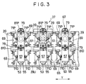
- Fig. 3 is a section view along the line III-III in Fig. 2.
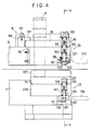
- Fig. 4 is a sectional view in a large scale taken on the arrow IV in Fig. 2.
- Fig. 5 is a sectional view taken along the line V-V in Fig. 4.
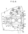
- Fig. 6 is a plan of an upper part of a turret shown in Fig. 4.
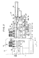
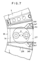
- Fig. 7 is a plan of a lower part of the turret shown in Fig. 4.
- Fig. 8 is a sectional view in a large scale taken on the arrow VIII-VIII in Fig. 2 showing the primary part of a second example of a turret punch press of the present invention.
- Fig. 9 is a sectional view along the line IX-IX in Fig. 8.
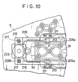
- Fig. 10 is a plan of an upper part of a turret shown in Fig. 8.
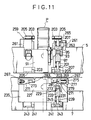
- Fig. 11 is a sectional view of a modified part of the second example of the punch press.
- Fig. 12 is a plan of an upper part of a turret shown in Fig. 11.
- Fig. 13 is a plan of a lower part of the turret shown in Fig. 11.
- Fig. 14 is a perspective drawing of a third example of a turret punch press of the present invention.
- Fig. 15 is a front view in a large scale taken on the arrow XV in Fig. 14.
- Fig. 16 is a plan of the part of the punch press shown in Fig. 15.
- Fig. 17 is a left side elevation of the part of the punch press shown in Fig. 15.
- Fig. 18 is a sectional view in a large scale taken on the arrow XVIII in Fig. 14.
- Fig. 19 is a sectional view along the line XIX-XIX in Fig. 18.
- Fig. 20 is a sectional view in a large scale taken on the arrow XX in Fig. 18.
- Fig. 21 is a sectional view along the line XXI-XXI in Fig. 20.
- Fig. 22 is a plan of an upper part of a turret shown in Fig. 20.
- Fig. 23 is a plan of a lower part of the turret shown in Fig. 20.
- a turret punch press of the first embodiment of the present invention is described.
- a turret punch press 1 is provided with a portal frame 3 in which at a central part a turret 9 consisted of an upper portion 5 and a lower portion 7 is supported by the frame 3.
- a plurality of punches P and dies D are attached in the upper portion 5 and the lower portion 7 of the turret 9 respectively at their circumferential parts.
- a processing location 11 is disposed in the turret punch press 1. After the turret 9 is rotated so that a die set 29 on the turret 9 is positioned at the processing location 11, a punching process starts on a workpiece W which has been positioned at the processing location 11. The punching is carried out by means of a punch P and a die D. The punch P is pressed by a striker (not shown) which is disposed above the processing location 11 and is actuated by driving means (not shown) disposed on the frame 3.
- the punch press 1 has a fixed center table 13 under the portal frame 3 and movable tables 15 provided beside the fixed center table 13.
- the movable tables 15 are guided by guides 17 which extend in a direction Y and are moved smoothly along the guides 17.
- a carriage base 19 extended in a direction X and provided with a positioning device 21 for positioning a workpiece W on the tables 13, 15 is attached.
- the carriage base 19 is provided with a carriage 23 which is movable in the direction X and to which a plurality of cramps 25 are attached for holding the workpiece W.
- the workpiece W held by the cramps 25 is moved in the directions X and Y when the movable tables 15 are moved in the direction Y and the carriage 23 is moved in the direction X, and then the workpiece W is subject to a punching process at the processing location 11.
- the turret 9 is located on the center, the workpiece positioning device 21 on the left side, and a die set storage area 27 in the portal frame 3 on the right side which is opposite to the workpiece positioning device 21.
- the die set storage area 27 includes a die set storage section 31 in which a large number of die sets 29 each consisted of an upper die having an appropriate number of punches and a lower die, are stored being spaced from each other in the directions Y and Z.
- the die sets 29 can be moved in the die set storage section 31 at least in the direction Z by conventional known means.
- each die set attaching area 33 is formed in almost U-shaped cuts for attaching die sets 29 and are spaced from each other appropriately.
- the turret 9 can be rotated, and each die set attaching area 33 can be positioned at a die exchanging position 35.
- an automatic die exchange device 37 is disposed, which is movable in the direction X and Y and is provided with a plurality of housings 39 or die carrying sections.
- the number of the die carrying sections or housings 39 is greater by one than the number of the die attaching areas 33 of the turret 9 in Fig. 1.
- a plurality of guide rails 43 which extend in a parallel direction Y are disposed on a lower frame 41 of the turret punch press 1, and all the housings 39 are slidably mounted integrally on the guide rails 43 through guide members 45.
- a ball screw 49 is rotatably supported by bearings 47 mounted on both ends of the lower frame 41, and a nut member 51 fixed to a common bottom plate 39U of the housings 39 is engaged with the ball screw 49.
- a plurality of guide rails 53 spaced appropriately and extended in a parallel direction X are disposed on the bottom plate 39U of the housings 39, and a plurality of X-axis carriages 57 are mounted on the guide rails 53 through guide members 55.
- a X-axis cylinder 61 is mounted on a side wall 39F (Fig. 2) for each housing 39, and an end of a piston rod 63 disposed in the cylinder 61 is attached to an end wall of the X-axis carriage at an upper part.
- Each housing 39 is provided with an engagement releasing device 65, while the X-axis carriage is provided with a die holding section 67 for holding the die set 29.
- the engagement releasing device 65 includes engaging members 71P and 71D which are disposed beside the housing 39 through guiding members 69, and which are connected at one end by a connecting member 73 as shown in Fig. 2.
- the engagement releasing device 65 is provided with an engagement releasing cylinder 75 on the wall 39F of the housing 39, and a piston rod 77 is disposed in the engagement releasing cylinder 75. An end of the piston rod 77 is connected to the connecting member 73.
- the die holding section 67 includes two holding bars 79 which are mounted on the X-axis carriage 57, and to top ends of which chuck devices 81P, 81D are attached as shown in Figs. 2 and 3.
- the holding bars 79 are connected integrally to two connecting bars 83 respectively which extend in the direction X.
- the connecting bars 83 are connected with each other at one end by a connecting member 85.
- the X-axis carriage 57 is provided with a holding cylinder 87 in which a piston rod 89 is attached, and a top end of the piston rod 89 is fixed to the connecting member 89.
- a die set 29 is attached in the die set attaching area 33 in an exchangeable manner.
- a U-shaped cut 5V is formed in the upper portion 5 of the turret 9 as the die attaching area 33, for attaching a die base or die holder 91 holding, for example, two punches P.
- the die base 91 is charged from and discharged to the right side (Fig. 6). Structure for holding the punches P in the die base 91 is not described here since it is known.
- engaging members 95 with engaging portions 93 are disposed (Fig. 5, on the right and left of an upper part), while pins 97 as engaging members which engage with the engaging members 95 are disposed to slide vertically in the upper portion 5 of the turret 9.
- pins 97 as engaging members which engage with the engaging members 95 are disposed to slide vertically in the upper portion 5 of the turret 9.
- a cut 5C in which an L-shaped supporting block 99 is disposed and fixed to the upper portion 5 with bolts.
- a hole is formed vertically through the supporting block 99, and a screwed bar 101 is inserted in the hole.
- an end of the screwed bar 101 is fixed to the engaging pin 97, and another end is fixed integrally to a supporting block 105 which supports a cam follower 103 in a rotatable manner.
- a spring 107 is disposed between the engaging pin 97 and the supporting block 99. The spring 107 is normally energized to press the engaging pin 97 upwards.
- the die base 91 and the upper portion 5 are designed so that the engaging pins 97 of the upper portion 5 of the turret 9 engage with the engaging members 95 of the die base 91 by means of the energized springs 107 when the die base 91 is charged and positioned. Therefore, positioning of the die base 91 is carried out precisely in the upper portion 5 of the turret 9 in the die attaching area 33.
- a pair of holding members 109 are attached with bolts 111 to a top surface of the upper portion 5 of the turret 9 at both sides of the cut 5V for holding the die base 91 within the cut 5V.
- an elastic member 113 made of gum or other material is fixed by means of bolts 115 under the each holding member 109 at an end portion of the holding member 109, which is an entrance of the die attaching area 33 for the die base 91.
- an L-shaped holding member 117 is attached with bolt 121 through a bracket 119 to the upper portion 5 near a front end of the cut 5V as shown in Fig. 4 and 6 for holding the die base 91 within the cut 5V.
- a U-shaped cut 7V is formed as the die attaching area 33 for attaching a die base or die holder 227 holding two dies D.
- the die base 227 is charged from and discharged to the right side (Fig. 7). Structure for holding the dies D in the die base 227 is not described here since it is known.
- engaging members 127 with engaging portions 125 are disposed (Fig. 5, on the right and left of a lower part), while pins 129 as engaging members which engage with the engaging members 127 are disposed to slide vertically in a supporting member 235 fixed to the lower portion 7 of the turret 9.
- a cut 7C At a lower part of the each engaging pin 129 in the lower portion 7 of the turret 9 there is formed a cut 7C in which an L-shaped supporting block 133 is disposed and fixed to the supporting member 235 with bolts.
- a hole is formed vertically through the supporting block 133, and a screwed bar 135 is inserted in the hole.
- An end of the screwed bar 135 is fixed to the engaging pin 129, and another end is fixed integrally to a supporting block 139 which supports a cam follower 137 in a rotatable manner.
- a spring 141 is disposed between the engaging pin 129 and the supporting block 133. The spring 141 is normally energized to press the engaging pin 129 upwards.
- the die base 227 and the lower portion 7 are so designed that the engaging pins 129 of the lower portion 7 of the turret 9 engage with the engaging members 127 of the die base 227 by means of the energized springs 141 when the die base 227 is charged and positioned. Therefore, positioning of the die base 227 is carried out precisely at the die attaching area 33 of the lower portion 7 of the turret 9.
- a pair of holding members 247 are attached with bolts 249 to the supporting member 235 at both sides of the cut 7V for holding the die base 227 within the cut 7V.
- an elastic member 251 made of gum or other material is fixed by means of bolts 149 under the each holding member 247 at an end portion of the holding member 247, which is an entrance of the die attaching area 33 for the die base 227.
- the chuck devices 81P, 81D are moved to the turret 9 and inserted in holes 255, 257 formed in the die bases 91, 227.
- the chuck devices 81P, 81D which are for example known collet chucks, are inserted in the holes 255, 257, the die bases 91, 227 are held automatically with the chuck devices 81P, 81D.
- the operation includes taking out the new die sets 29 from the die set storage section 31 and charging the die sets 29 into all the die set attaching areas 33 when each area 33 is at the die exchanging position 35 and discharging die sets from each area 33 at the die exchanging position 35 and storing the die sets taken out from each area 33 in the die set storage section 31.
- the holding cylinder 87 is actuated until the chuck devices 81P, 81D come in the holes 255, 257 formed in the die bases 91, 227 to hold the die bases 91, 227, and then the die set 29 is discharged from the turret 9 by actuating the cylinder 87.
- the engagement releasing cylinder 75 and the X-axis cylinder 61 are then actuated to withdraw the engaging members 71P, 71D and the X-axis carriage 57 respectively away from the turret 9.
- the engaging pins 97, 129 are raised by action of the energized springs 107, 141 as the engaging members 71P, 71D have been withdrawn from the turret 9.
- housings 39 are moved a little in the direction Y so that one of housings 39 which holds a die set 29 taken out from die set storage section 31 is located at the die exchanging position 35, and the engagement releasing cylinder 75 is actuated to press down the cam follower 103, 137, while the X-axis carriage 57 is moved forwards to charge the die set 29 into the die attaching area 33 which is at the die exchanging position 35.
- the holding cylinder 87 is operated to withdraw the chuck devices 81P, 81D from the holding holes 255, 257, while the engagement releasing cylinder 75 is operated to withdraw the engaging members 71P, 71D. Therefore, the engaging pins 97, 129 engage with the engaging portions 93, 125 of the engaging members 95, 127 by action of the springs 107, 141, and the die set 29 is set in the die attaching area 33.
- another die set 29 in a die attaching area 33 is discharged from the turret 9 after the die attaching area 33 is located at the die exchanging position 35 by rotating the turret 9, and another die set 29 taken out from the die set storage section 31 is set in the die attaching area 33 in the same way mentioned above.
- a housing 39 is used to take out one die set from the die set storage section 31, and an empty housing is used to discharge a die set to be exchanged from the turret 9.
- the die exchanging device 37 is provided with a plurality of housings 39 to exchange a plurality of die sets 29 at a time, it is possible to shorten time for exchanging some die sets required for a processing.
- the die bases are charged into and discharged from the upper and the lower portions of the turret horizontally by the die exchanging device, therefore exchanging of die sets will be carried out with ease even if a space between the upper portion and the lower portion is small in a vertical direction.
- the press can be, for example, provided with more than three die attaching areas and the housings.
- the die set storage area 27 may be disposed outside the press instead of in the portal frame 3 of the press.
- the engaging pins 97, 129 may be rotated for engaging with the engaging members 95, 127 instead of moving vertically.
- a turret punch press 1 of a second embodiment of the present invention is shown.
- Fig. 7 is a plan for a lower portion of the turret 9 of a turret punch press of the first embodiment.
- Fig. 7 is also a plan for a lower portion of a turret 9 of the turret punch press 1 of the second embodiment, and therefore the plan is referred here.
- An outline of structure of the turret punch press 1 is the same as the first embodiment mentioned above. Same numerals are used for almost of the same structural elements in the second embodiment.
- a feature of the turret punch press of the second embodiment is that the press has other elements for fixing the die set 29 in the die attaching area 33. The feature is now described in detail.
- Figs. 8 to 10 the die base 91 attached in the upper portion 5 of of the turret 9 is shown.
- the die base 91 is provided with engaging members 95 having conical engaging parts 93.
- two engaging members or pins 97 are slidably disposed for engaging with the engaging parts 93 of the engaging members 95 of the die base 91, and also a cut 5C is formed at a lower part of the each engaging pin 97.
- An L-shaped supporting block 99 is disposed in the each cut 5C and is fixed to the upper portion 5 by means of bolts.
- a hole is formed vertically through the supporting block 99, and a screwed bar 201 is inserted in the hole.
- An end of the screwed bar 201 is fixed to the engaging pin 97, and another end is fixed integrally to a supporting block 205 which supports a cam follower 203 in a rotatable manner.
- a spring 207 is disposed between the engaging pin 97 and the supporting block 99. The spring 207 is normally energized to press the engaging pin 97 upwards.
- a fixing member 209 is mounted on the upper portion 5 for pressing down the die base 91 not to come upwards out of the attaching area 33.
- the fixing member 209 is U-shaped as shown in Fig. 10, and is supported by pins 211 which are inserted in levers 209a of the member 209 and which are supported by bearings 213 fixed to the portion 5 of the turret 9, so that the member 209 rotates free around the pin 211.
- a base 209b of the fixing member 209 is attached to the portion 5 with two bolts 217 embedded in the portion 5, and is normally pressed upwards by action of tension springs 219 disposed around the bolts 217 between the base 209b and the portion 5. Therefore, round lower surfaces 215 formed at front ends of the fixing member 209 press down the die base 91.
- a driving member 223 is supported from the portal frame 3 through a bracket 221 for pressing down the base 209b of the fixing member 209.
- the driving member 223 is, for example, a pneumatic cylinder provided with a piston rod 225.
- the fixing member 209 rotates clockwise by the action of the spring 219 and press down the die base 91 to fix it securely to the portion 5.
- a U-shaped cut 7V is formed for attaching a die base or die holder 227 holding two dies D (Fig. 2).
- the die base 227 is charged from and discharged to the right side (Fig. 7).
- engaging members 231 with engaging portions 229 are disposed in the die base 227, while engaging pins or members 233 for engaging with the engaging members 231 are disposed to slide vertically in a supporting member 235 fixed to the lower portion 7 of the turret 9.
- a supporting member 235 fixed to the lower portion 7 of the turret 9.
- a hole is formed vertically through the supporting block 237, and a screwed bar 239 is inserted in the hole.
- An end of the screwed bar 239 is fixed to the engaging pin 233, and another end is fixed integrally to a supporting block 243 which supports a cam follower 241 in a rotatable manner.
- a spring 245 is disposed between the engaging pin 233 and the supporting block 237. The spring 245 is normally energized to press the engaging pin 233 upwards.
- the die base 227 and the lower portion 7 are so designed that the engaging pin 233 of the lower portion 7 of the turret 9 engages with the engaging member 231 of the die base 227 by means of the energized spring 141 when the die base 227 is charged and positioned. Therefore, positioning of the die base 227 is carried out precisely in the lower portion 7 of the turret 9 in the die attaching area 33.
- a pair of holding members 247 are attached with bolts 249 to the supporting member 235 at both sides of the cut 7V for holding the die base 227 within the cut 7V.
- an elastic member 251 made of gum or other material is fixed by means of bolts 253 under the each holding member 247 at an end portion of the holding member 247, which is an entrance of the die attaching area 33 for the die base 227.
- the chuck devices 81P, 81D are moved to the turret 9 and inserted in the holes 255, 257 formed in the die bases 91, 227 (Fig.2).
- the chuck devices 81P, 81D are inserted in the holes 255, 257, the die bases 91, 227 are held automatically with the chuck devices 81P, 81D as mentioned in the above.
- the fixing member 209 is used during the operation.
- the driving member 223 is activated to press down the base 209b of the fixing member 209 so that the contact surfaces 215 of the fixing member 209 to be raised.
- the fixing member 209 is used to press down the die set 29 after the die set 29 has been charged in the turret 9.
- a modified example for the second embodiment is shown, in which the same reference numerals is used for the same elements, and description is omitted for them.
- pressing elements for pressing down the die bases 91, 227 in the upper and lower portions 5, 7 are different from the example shown in Figs. 7 to 10.
- Elements for pressing a die base 91 attached in the upper portion 5 of the turret 9 are pressing members 259 which are disposed on a supporting block 261 mounted on the upper portion 5.
- An engaging member 263 is inserted in each supporting block 261.
- a screwed bar 265 is inserted and fixed in the engaging member 263, and an upper end of the screwed bar 265 is integrally fixed to a supporting block 205 by which a cam follower 203 is supported rotatably.
- a spring 207 is disposed between the engaging member 263 and the supporting block 261 so that the engaging member 263 is normally pressed downwards by the spring 207.
- Elements for pressing a die base 227 attached in the lower portion 7 of the turret 9 are pressing members 267 which are fixed to the supporting member 235 of the lower portion 7 by means of bolts, etc.
- An engaging member 269 slidable to the right and the left (Fig. 11) is disposed in each pressing member 267 as a fixing member for fixing the die base 227 in the portion 7.
- a guide bar 277 for guiding the engaging member 269 is fixed to a base plate 275 which is formed integrally in the pressing member 267.
- a coil spring 279 is disposed around the guide bar 277 and between the engaging member 269 and the base plate 275, and is normally energized to press the engaging member 269 towards the left side for pressing down the die base 227.
- the pressing member 267 is provided with a step 281 at which the engaging member 269 stops and with a hole in which the engaging member 71D of the engagement releasing device 65 is to be inserted.
- fixing releasing elements such as engagement releasing device 65 and the driving member 223 are disposed outside the turret 9, and only fixing elements such as the engaging or fixing members 209, 263, 269 and pins 97, 129, 233 and springs 107, 207, 141, 219, 279, which are relatively small, light, and of simple structure, are mounted on the turret 9 in the turret punch press of the second embodiment So, the turret 9 can be of compact size and simple structure, and therefore it does not require large space, and is manufactured in low cost and easy to maintain. In addition, positioning of die bases is carried out with ease and precisely due to the conical engaging parts 93, 229.
- a turret punch press of a third embodiment and a die exchanging device of the present invention are described.
- a turret punch press 301 is provided with a portal frame 303 in which at the central part a turret 309 consisted of an upper portion 305 and a lower portion 307 is supported by the frame 303.
- a plurality of die sets 329 are to be attached in the turret 309 at die set attaching areas 333 which are formed at a circumferential part of the turret 309.
- a processing location 311 is disposed in the turret punch press 301. After the turret 309 is rotated so that a die set 329 on the turret 309 is positioned at the processing location 311, a punching process starts on a workpiece W which has been positioned at the processing location 311.
- the punching is carried out by means of a punch P and a die D.
- the punch P is pressed by a striker (not shown) which is disposed above the processing location 311 and is actuated by driving means (not shown) disposed on the frame 303.
- the punch press 301 has a fixed center table 313 under the portal frame 303 and two movable tables 315 provided beside the fixed center table 313.
- the movable tables 315 are guided by guides 317 which extend in a direction Y, and are therefore moved smoothly along the guides 317.
- a carriage base 319 extended in a direction X and provided with a positioning device 321 for positioning a workpiece W on the tables 313, 315 is disposed.
- the carriage base 319 is provided with a carriage 323 which is movable in the direction X and to which a plurality of cramps 325 are attached for holding the workpiece W.
- the workpiece W held by the cramps 325 is moved in the directions X and Y when the movable tables 315 are moved in the direction Y and the carriage 323 is moved in the direction X, and then the workpiece W is subject to a punching process at the processing location 311.
- the turret 309 is located on the center, the workpiece positioning device 321 on the left side, and a die set storage area 327 in the portal frame 303 on the right side which is opposite to the workpiece positioning device 321.
- the die set storage area 327 includes a die set storage section 331 in which a large number of die sets 329 each consisted of an upper die having an appropriate number of punches and a lower die, are stored and spaced from each other in the directions Y and Z.
- the die sets 329 can be moved in the storage section 331 at least in the direction Z by conventional known means.
- a plurality of die set attaching areas 333 are formed in almost U-shaped cuts on the circumferential part of the turret 309 for attaching die sets 329.
- the die set attaching areas 333 are spaced from each other appropriately and opposed to each other.
- the turret 309 can be rotated, so that each die set attaching area 333 can be positioned at a die exchanging position 335.
- a die exchange device 337 is disposed, which is movable in the direction X and Y and is provided with a plurality of housings 339 or die carrying sections.
- the number of the die carrying sections or housings 339 is four and is greater by one than the number of the die attaching areas 333 of the turret 309 for this example shown in Fig. 14.
- the die exchanging device 337 is also provide with die carrying means 343 which include a plate 341 supported by a support (not shown) and two guide rails 345 mounted on the plate 341 and spaced from each other.
- the plate 341 and the guide rails 345 extend in a direction Y.
- All the housing 339 are integrally mounted on the guide rails 341 through guide members 351 (not shown in Fig. 14).
- a ball screw 347 is mounted on the plate 341 and between the two guide rails 345 for moving the housing 339 horizontally.
- Figs. 15 to 17 details about the die carrying means 343 are described.
- the plate 341 is supported by a support through a bracket 359 as shown in Fig. 17.
- the guide rails 345 on the plate 341 are engaged with guide members 351 such as LM guides, etc. fixed to a bracket 349 which supports the housing 339.
- the ball screw 347 is supported in a rotatable manner by bearings 353 disposed on the plate 341 as shown in Fig. 15.
- a screwed nut engages with the ball screw 347 and joints entire housings 339 and the supporting bracket 349.
- a motor 357 is disposed at an end of the ball screw 347 for driving it.
- the ball screw 347 rotates, and then the housings 339 moves in the direction Y through the nut member 355.
- the housings 339 moves smoothly since they are guided by the guide rails 345.
- Fig. 15 three positions where the housings 339 stand is shown. At the left position die sets are charged into and discharged from the turret 309 for exchanging the die sets, at the middle position the housings 339 stand waiting for next action, and at the right position die sets are taken out from and stored in the die set storage section 331.
- the housings 339 of the die exchanging device 337 are located at the right position in front of the storage section 331, and some die sets are taken out and held in the housings, and then the housings wait at the middle position until they receive an order for exchanging the die sets. If the housings receive the order, they move to the die exchanging position 335, and the die sets are exchanged by the die exchange device 337.
- the guide members 351 are spaced and disposed on a front plate 349a of the supporting bracket 349, and are engaged in a slidable manner with the guide rails 345 which are sixed to a plate 341 mounted on the bracket 359.
- the ball screw 347 is supported in a rotatable manner by the bearings 353 mounted on the plate 341 at both ends of it, and is also engaged with a nut 355 fixed to the front plate 349a of the supporting bracket 349.
- a plurality of guide bars 361 extended in the direction X are disposed in the housing 339.
- a X-axis carriage 365 is mounted on the guide bars 361 through a plurality of bushings 363.
- a rodless cylinder 367 is fixed to the housing 339 by fixing both ends of a cylinder part 369 of the rodless cylinder 367 to the housing 339 with rock nuts 371.
- a driving portion 373 for driving the cylinder 367 is attached to the X-axis carriage 365.
- Each housing 339 is provided with an engagement releasing device 374, while the X-axis carriage 365 is provided with a die holding section 375 for holding the die set 329.
- the engagement releasing device 374 includes engaging members 379P and 379D which are disposed beside the housing 339 through guiding members 377, and which are connected at one end by a connecting member 381 as shown in Figs. 18 and 19.
- the engagement releasing device 374 is provided with an engagement releasing cylinder 385 disposed in a rotatable manner on the front plate 349a of the supporting bracket 349 through a hinged block 383, and a piston rod 387 is disposed in the engagement releasing cylinder 387.
- a joint 389 is disposed for connecting an end of the piston rod 387 and an end of the link 391.
- the link 391 is hinged at the end in the joint 389, at the middle supported in a rotatable manner by an axis 393 mounted on the housing, and is at the other end engaged with a pin 395 mounted on the connecting member 381.
- the die holding section 375 includes two holding bars 397 which are mounted on the X-axis carriage 365, and to front ends of which chuck devices 399P, 399D are attached as shown in Figs. 18 and 19.
- the holding bars 397 are connected integrally to two holding cylinders 401 respectively which are attached to the X-axis carriage 365.
- Piston rods 403 of the holding cylinders 401 penetrate the holding bars 397, and to ends of the piston rods 403 the chuck devices 399P, 399D are attached.
- the piston rods 403 are normally pressed to withdraw (to the right, in Fig. 18) by action of springs 405 disposed in the holding bars 397.
- the structure of the chuck devices 399P, 399D is that of a collet chuck.
- a die set 329 is attached in the die set attaching area 333 in an exchangeable manner.
- a U-shaped cut 5V is formed in the upper portion 305 of the turret 309 as the die attaching area 333 for attaching a die base or die holder 407 holding an appropriate number of punches P (for example, two or three as shown in Fig. 18).
- the die base 407 is charged from and discharged to the right side (Fig. 6).
- engaging members 411 with engaging portions 409 are disposed (Fig. 21, on the right and left of an upper part), while pins 413 as engaging members which engage with the engaging members 411 are disposed to slide vertically in the upper portion 305 of the turret 309.
- a cut 5C in which an L-shaped supporting block 415 is disposed and fixed to the upper portion 305 with bolts.
- a hole is formed vertically through the supporting block 415, and a screwed bar 417 is inserted in the hole.
- a spring 423 is disposed between the engaging pin 413 and the supporting block 415.
- the spring 423 is normally energized to press the engaging pin 413 upwards.
- the die base 407 and the upper portion 305 are designed so that the engaging pins 413 of the upper portion 305 of the turret 309 engage with the engaging members 411 of the die base 407 by means of the energized springs 423 when the die base 407 is charged and positioned. Therefore, positioning of the die base 407 is carried out precisely at the die attaching area 333 of the upper portion 305 of the turret 309.
- a pair of holding members 425 are attached with bolts 427 to a top surface of the upper portion 305 of the turret 309 at both sides of the cut 5V for holding the die base 407 within the cut 5V.
- an elastic member 429 made of gum or other material is fixed by means of bolts 431 under the each holding member 425 at an end portion of the holding member 425, which is an entrance of the die attaching area 333 for the die base 407.
- an L-shaped holding member 433 is attached with bolt 121 through a bracket 435 to the upper portion 305 near a front end of the cut 5V as shown in Fig. 20 and 22 for holding the die base 407 within the cut 5V.
- a U-shaped cut 7V is formed as the die attaching area 333 for attaching a die base or die holder 439 holding two dies D.
- the die base 439 is charged from and discharged to the right side (Fig. 7).
- engaging members 443 with engaging portions 441 are disposed (Fig. 21 on the right and left of a lower part), while pins 445 as engaging members which engage with the engaging members 443 are disposed to slide vertically in a supporting member 447 fixed to the lower portion 307 of the turret 309.
- a cut 7C At a lower part of the each engaging pin 445 in the lower portion 307 of the turret 309 there is formed a cut 7C in which an L-shaped supporting block 449 is disposed and fixed to the supporting member 447 with bolts.
- a hole is formed vertically through the supporting block 449, and a screwed bar 451 is inserted in the hole.
- An end of the screwed bar 451 is fixed to the engaging pin 445, and another end is fixed integrally to a supporting block 455 which supports a cam follower 453 in a rotatable manner.
- a spring 457 is disposed between the engaging pin 445 and the supporting block 449. The spring 457 is normally energized to press the engaging pin 445 upwards.
- the die base 439 and the lower portion 307 are so designed that the engaging pins 445 of the lower portion 307 of the turret 309 engage with the engaging members 443 of the die base 439 by means of the energized springs 457 when the die base 439 is charged and positioned. Therefore, positioning of the die base 439 is carried out precisely at the die attaching area 333 of the lower portion 307 of the turret 309.
- a pair of holding members 459 are attached with bolts 461 to the supporting member 447 at both sides of the cut 7V for holding the die base 439 within the cut 7V.
- an elastic member 463 made of gum or other material is fixed by means of bolts 465 under the each holding member 459 at an end portion of the holding member 459, which is an entrance of the die attaching area 333 for the die base 439.
- the chuck devices 399P, 399D are moved to the turret 309 and inserted in holes 467, 469 formed in the die bases 407, 439.
- the chuck devices 399P, 399D which are for example known collect chucks, are inserted in the holes 467, 469, the die bases 407, 439 are held automatically with the chuck devices 399P, 399D.
- the operation includes taking out the new die sets 329 from the die set storage section 331 and charging the die sets 329 into all the die set attaching areas 333 when each area 333 is at the die exchanging position 335 and discharging die sets from each area 333 at the die exchanging position 335 and storing the die sets taken out from each area 333 in the die set storage section 331.
- the holding cylinder 401 is actuated until the chuck devices 399P, 399D come in the holes 467, 469 formed in the die bases 407, 439 to hold the die bases 407, 439, and then the die set 329 is discharged from the turret 309 by actuating the cylinder 401.
- the engagement releasing cylinder 385 and the rodless cylinder 367 are then actuated to withdraw the engaging members 379P, 379D and the X-axis carriage 365 respectively away from the turret 309.
- the engaging pins 413, 445 are raised by action of the energized springs 423, 457 as the engaging members 379P, 379D have been withdrawn from the turret 309.
- housings 339 are moved a little in the direction Y so that one of housings 339 which holds a die set 329 taken out from die set storage section 331 is located at the die exchanging position 335, and the engagement releasing cylinder 385 is actuated to press down the cam follower 419, 453, while the X-axis carriage 365 is moved forwards to charge the die set 329 into the die attaching area 333 which is at the die exchanging position 335.
- the holding cylinder 401 is operated to withdraw the chuck devices 399P, 399D from the holding holes 467, 469, while the engagement releasing cylinder 385 is operated to withdraw the engaging members 379P, 379D. Therefore, the engaging pins 413, 445 engage with the engaging portions 409, 441 of the engaging members 411, 443 by action of the springs 423, 457, and the die set 329 is set in the die attaching area 333.
- one or two housings 339 are used to take out one or two die sets from the die set storage section 331, and an empty housing is used to discharge a die set to be exchanged from the turret 309.
- all the die sets 329 on the turret 309 are exchanged quickly by the die exchanging device 337 which moves only on a plane horizontally at the height of the die attaching area 333 which is at the die exchanging position 335.
Landscapes
- Engineering & Computer Science (AREA)
- Mechanical Engineering (AREA)
- Punching Or Piercing (AREA)
- Mounting, Exchange, And Manufacturing Of Dies (AREA)
- Perforating, Stamping-Out Or Severing By Means Other Than Cutting (AREA)
- Encapsulation Of And Coatings For Semiconductor Or Solid State Devices (AREA)
- Lead Frames For Integrated Circuits (AREA)
- Press Drives And Press Lines (AREA)
Abstract
Description
- The present invention relates to a die exchanging device for a punch press and to a turret punch press provided with such a die exchanging device.
- In the prior art, a finite number of die sets are attached in a turret of a turret punch press, and the die sets are exchanged by man power. Sometimes, an automatic die exchanging device is used to discharge die sets attached in the turret and to charge other die sets in the turret for next use.
- The above mentioned conventional automatic die exchanging device includes a pair of arms, that is, a first arm for discharging die sets from the turret and a second arm for taking other die sets out from a die storage magazine.
- By the way, in the above mentioned conventional automatic die exchanging device the pair of arms only carry out discharging and taking out of a die set respectively from the turret and the die storage magazine at the same time and only exchanges the die sets. Therefore, it is necessary to exchange die sets several times when some die sets are required for one processing on a workpiece, and this takes much time totally.
- In addition, it is necessary to move the arms upwards and downwards since heights of the die storage magazine and a die set attached in the punch press for use differ from each other. Due to such movements of the arms, which is complicated, the die exchanging device requires large space and much time for exchanging of the die sets. Furthermore, structure of the device becomes complicated for moving the arms, and, as a result, the exchanging device will cost much and take much time for possible repairing or maintaining.
- By the way, in a conventional turret punch press with a die exchanging device, for example, a method for positioning and fixing a die set in the turret is generally used by pushing the die set to come into contact with a reference surface disposed on the turret and fixing it by means of a hydraulic pressing device.
- In the above mentioned positioning and fixing method, the contact of the die set with the reference surface of the turret is surface-to-surface contact, and therefore it is difficult to cause the die set to come into contact with the reference surface uniformly by reason of processing precision. Then an error for positioning arises.
- Furthermore, the hydraulic pressing device is disposed on the turret, and therefore the punch press becomes complicated in structure and cost much, and it requires large space as a result. Moreover, time lag occurs, and maintenance becomes necessary for the use of hydraulic operation.
- A turret punch press according to the preamble of claim 1 is known from EP-A-0138122.
- This known turret punch press uses a magazine cassette which is adapted to carry out a variety of tools. When new tools are to be changed and mounted on the turret of the punch press and the new tools are supported on a cassette which is located in the magazine rather than the cassette next to the turret, the cassette which is next to the turret has to be removed first and moved to the magazine and then the new cassette supporting the new tools has to be moved next to the turret.
- It is the object of the present invention, to improve the above mentioned disadvantages and provide a turret punch press, which exchanges die sets quickly.
- This object is solved according to the presention invention by the subject matter of claim 1.
- Preferred embodiments of the invention are the subject matter of the dependent claims.
- Fig. 1 is a perspective drawing of an example of a turret punch press of the present invention.
- Fig. 2 is a sectional view in a large scale taken on the arrow II in Fig. 1.
- Fig. 3 is a section view along the line III-III in Fig. 2.
- Fig. 4 is a sectional view in a large scale taken on the arrow IV in Fig. 2.
- Fig. 5 is a sectional view taken along the line V-V in Fig. 4.
- Fig. 6 is a plan of an upper part of a turret shown in Fig. 4.
- Fig. 7 is a plan of a lower part of the turret shown in Fig. 4.
- Fig. 8 is a sectional view in a large scale taken on the arrow VIII-VIII in Fig. 2 showing the primary part of a second example of a turret punch press of the present invention.
- Fig. 9 is a sectional view along the line IX-IX in Fig. 8.
- Fig. 10 is a plan of an upper part of a turret shown in Fig. 8.
- Fig. 11 is a sectional view of a modified part of the second example of the punch press.
- Fig. 12 is a plan of an upper part of a turret shown in Fig. 11.
- Fig. 13 is a plan of a lower part of the turret shown in Fig. 11.
- Fig. 14 is a perspective drawing of a third example of a turret punch press of the present invention.
- Fig. 15 is a front view in a large scale taken on the arrow XV in Fig. 14.
- Fig. 16 is a plan of the part of the punch press shown in Fig. 15.
- Fig. 17 is a left side elevation of the part of the punch press shown in Fig. 15.
- Fig. 18 is a sectional view in a large scale taken on the arrow XVIII in Fig. 14.
- Fig. 19 is a sectional view along the line XIX-XIX in Fig. 18.
- Fig. 20 is a sectional view in a large scale taken on the arrow XX in Fig. 18.
- Fig. 21 is a sectional view along the line XXI-XXI in Fig. 20.
- Fig. 22 is a plan of an upper part of a turret shown in Fig. 20.
- Fig. 23 is a plan of a lower part of the turret shown in Fig. 20.
- Now embodiments of the present invention will be described in detail with reference to attached drawings.
- In Fig. 1-7, a turret punch press of the first embodiment of the present invention is described.
- In Fig. 1, a turret punch press 1 is provided with a
portal frame 3 in which at a central part aturret 9 consisted of anupper portion 5 and alower portion 7 is supported by theframe 3. A plurality of punches P and dies D are attached in theupper portion 5 and thelower portion 7 of theturret 9 respectively at their circumferential parts. - A processing location 11 is disposed in the turret punch press 1. After the
turret 9 is rotated so that adie set 29 on theturret 9 is positioned at the processing location 11, a punching process starts on a workpiece W which has been positioned at the processing location 11. The punching is carried out by means of a punch P and a die D. The punch P is pressed by a striker (not shown) which is disposed above the processing location 11 and is actuated by driving means (not shown) disposed on theframe 3. - The punch press 1 has a fixed center table 13 under the
portal frame 3 and movable tables 15 provided beside the fixed center table 13. The movable tables 15 are guided byguides 17 which extend in a direction Y and are moved smoothly along theguides 17. At left ends of the movable tables 15 acarriage base 19 extended in a direction X and provided with apositioning device 21 for positioning a workpiece W on the tables 13, 15 is attached. Thecarriage base 19 is provided with acarriage 23 which is movable in the direction X and to which a plurality ofcramps 25 are attached for holding the workpiece W. - Therefore, the workpiece W held by the
cramps 25 is moved in the directions X and Y when the movable tables 15 are moved in the direction Y and thecarriage 23 is moved in the direction X, and then the workpiece W is subject to a punching process at the processing location 11. - In the turret punch press 1, the
turret 9 is located on the center, theworkpiece positioning device 21 on the left side, and a dieset storage area 27 in theportal frame 3 on the right side which is opposite to theworkpiece positioning device 21. The dieset storage area 27 includes a dieset storage section 31 in which a large number ofdie sets 29 each consisted of an upper die having an appropriate number of punches and a lower die, are stored being spaced from each other in the directions Y and Z. The diesets 29 can be moved in the dieset storage section 31 at least in the direction Z by conventional known means. - On the circumferential part of the turret 9 a plurality of die set attaching
areas 33 are formed in almost U-shaped cuts for attaching diesets 29 and are spaced from each other appropriately. Theturret 9 can be rotated, and each die set attachingarea 33 can be positioned at a die exchangingposition 35. - In front of the
die exchanging position 35 and the die setstorage section 31, an automaticdie exchange device 37 is disposed, which is movable in the direction X and Y and is provided with a plurality ofhousings 39 or die carrying sections. The number of the die carrying sections orhousings 39 is greater by one than the number of thedie attaching areas 33 of theturret 9 in Fig. 1. - As shown in detail in Figs. 1-3, a plurality of
guide rails 43 which extend in a parallel direction Y are disposed on alower frame 41 of the turret punch press 1, and all thehousings 39 are slidably mounted integrally on the guide rails 43 throughguide members 45. - A
ball screw 49 is rotatably supported bybearings 47 mounted on both ends of thelower frame 41, and anut member 51 fixed to acommon bottom plate 39U of thehousings 39 is engaged with theball screw 49. - When a driving motor (not shown) is actuated the ball screw rotates, and then the
housings 39 moves in the direction Y through thenut member 51. Thehousings 39 moves smoothly since they are guided by the guide rails 43. - A plurality of
guide rails 53 spaced appropriately and extended in a parallel direction X are disposed on thebottom plate 39U of thehousings 39, and a plurality ofX-axis carriages 57 are mounted on the guide rails 53 throughguide members 55. - A
X-axis cylinder 61 is mounted on aside wall 39F (Fig. 2) for eachhousing 39, and an end of apiston rod 63 disposed in thecylinder 61 is attached to an end wall of the X-axis carriage at an upper part. - When the
piston rod 63 of theX-axis cylinder 61 is actuated theX-axis carriage 57 moves in the direction X. TheX-axis carriage 57 moves smoothly since it is guided by the guide rails 53. - Each
housing 39 is provided with anengagement releasing device 65, while the X-axis carriage is provided with adie holding section 67 for holding the die set 29. Theengagement releasing device 65 includes engagingmembers housing 39 through guidingmembers 69, and which are connected at one end by a connectingmember 73 as shown in Fig. 2. - The
engagement releasing device 65 is provided with anengagement releasing cylinder 75 on thewall 39F of thehousing 39, and apiston rod 77 is disposed in theengagement releasing cylinder 75. An end of thepiston rod 77 is connected to the connectingmember 73. - When the
piston rod 77 of thecylinder 75 is actuated the engagingmembers member 73 move in the direction X. The engagingmembers members 69 when move. - The
die holding section 67 includes two holdingbars 79 which are mounted on theX-axis carriage 57, and to top ends of whichchuck devices bars 83 respectively which extend in the direction X. The connecting bars 83 are connected with each other at one end by a connectingmember 85. TheX-axis carriage 57 is provided with a holdingcylinder 87 in which a piston rod 89 is attached, and a top end of the piston rod 89 is fixed to the connecting member 89. - When the piston rod 89 of the
cylinder 87 is actuated thechuck devices member 85 and the connecting bars 83. - A die set 29 is attached in the die
set attaching area 33 in an exchangeable manner. As shown in detail in Fig. 2 and Figs. 4 to 7, aU-shaped cut 5V is formed in theupper portion 5 of theturret 9 as thedie attaching area 33, for attaching a die base or dieholder 91 holding, for example, two punches P. Thedie base 91 is charged from and discharged to the right side (Fig. 6). Structure for holding the punches P in thedie base 91 is not described here since it is known. - In the
die base 91 engagingmembers 95 with engagingportions 93 are disposed (Fig. 5, on the right and left of an upper part), whilepins 97 as engaging members which engage with the engagingmembers 95 are disposed to slide vertically in theupper portion 5 of theturret 9. At a lower part of the each engagingpin 97 in theupper portion 5 of theturret 9 there is formed acut 5C in which an L-shaped supportingblock 99 is disposed and fixed to theupper portion 5 with bolts. A hole is formed vertically through the supportingblock 99, and a screwedbar 101 is inserted in the hole. And an end of the screwedbar 101 is fixed to the engagingpin 97, and another end is fixed integrally to a supportingblock 105 which supports acam follower 103 in a rotatable manner. Aspring 107 is disposed between the engagingpin 97 and the supportingblock 99. Thespring 107 is normally energized to press the engagingpin 97 upwards. Thedie base 91 and theupper portion 5 are designed so that the engagingpins 97 of theupper portion 5 of theturret 9 engage with the engagingmembers 95 of thedie base 91 by means of the energizedsprings 107 when thedie base 91 is charged and positioned. Therefore, positioning of thedie base 91 is carried out precisely in theupper portion 5 of theturret 9 in thedie attaching area 33. - As shown in Figs. 5 and 6 a pair of holding
members 109 are attached withbolts 111 to a top surface of theupper portion 5 of theturret 9 at both sides of thecut 5V for holding thedie base 91 within thecut 5V. For protecting thedie base 91 not to be damaged when it is charged in thedie attaching area 33, anelastic member 113 made of gum or other material is fixed by means ofbolts 115 under the each holdingmember 109 at an end portion of the holdingmember 109, which is an entrance of thedie attaching area 33 for thedie base 91. In addition, an L-shaped holdingmember 117 is attached withbolt 121 through abracket 119 to theupper portion 5 near a front end of thecut 5V as shown in Fig. 4 and 6 for holding thedie base 91 within thecut 5V. - In the
lower portion 7 of the turret 9 aU-shaped cut 7V is formed as thedie attaching area 33 for attaching a die base or dieholder 227 holding two dies D. Thedie base 227 is charged from and discharged to the right side (Fig. 7). Structure for holding the dies D in thedie base 227 is not described here since it is known. - In the
die base 227 engagingmembers 127 with engagingportions 125 are disposed (Fig. 5, on the right and left of a lower part), whilepins 129 as engaging members which engage with the engagingmembers 127 are disposed to slide vertically in a supportingmember 235 fixed to thelower portion 7 of theturret 9. At a lower part of the eachengaging pin 129 in thelower portion 7 of theturret 9 there is formed acut 7C in which an L-shaped supportingblock 133 is disposed and fixed to the supportingmember 235 with bolts. A hole is formed vertically through the supportingblock 133, and a screwedbar 135 is inserted in the hole. An end of the screwedbar 135 is fixed to theengaging pin 129, and another end is fixed integrally to a supportingblock 139 which supports acam follower 137 in a rotatable manner. Aspring 141 is disposed between theengaging pin 129 and the supportingblock 133. Thespring 141 is normally energized to press the engagingpin 129 upwards. Thedie base 227 and thelower portion 7 are so designed that the engagingpins 129 of thelower portion 7 of theturret 9 engage with the engagingmembers 127 of thedie base 227 by means of the energizedsprings 141 when thedie base 227 is charged and positioned. Therefore, positioning of thedie base 227 is carried out precisely at thedie attaching area 33 of thelower portion 7 of theturret 9. - As shown in Figs. 5 and 7 a pair of holding
members 247 are attached withbolts 249 to the supportingmember 235 at both sides of thecut 7V for holding thedie base 227 within thecut 7V. For protecting thedie base 227 not to be damaged when it is charged in thecut 7V of thedie attaching area 33, anelastic member 251 made of gum or other material is fixed by means ofbolts 149 under the each holdingmember 247 at an end portion of the holdingmember 247, which is an entrance of thedie attaching area 33 for thedie base 227. - As shown in Fig. 4, when the engaging
members engagement releasing device 65 are moved to theturret 9, inclined parts of ends of the engagingmembers cam followers pins blocks bars springs pins members upper portion 5 and the supportingmember 235 of thelower portion 7 respectively, that is, ready to be discharged from the dieset attaching area 33. - Then, the
chuck devices turret 9 and inserted inholes chuck devices holes chuck devices - Now, an operation for exchanging all die sets (two sets for this example) attached in the die
set attaching areas 33 of theturret 9 is explained. The operation includes taking out the new die sets 29 from the die setstorage section 31 and charging the die sets 29 into all the dieset attaching areas 33 when eacharea 33 is at thedie exchanging position 35 and discharging die sets from eacharea 33 at thedie exchanging position 35 and storing the die sets taken out from eacharea 33 in the die setstorage section 31. - First, all the
housings 39, each of which is now empty, are moved in the direction Y until they come in front of the die setstorage section 31. Then, theX-axis cylinders 61 for two housings of the three are actuated to move theX-axis carriages 57 towards the die setstorage section 31, and the holdingcylinders 87 are actuated for the two to move thechuck devices holes die bases sets 29 which are arranged in thestorage section 31 at a same height of the dieset attaching area 33 at thedie exchanging position 35. By the action of thecylinders housings 39 of the three hold two die sets. - Then, all the
housings 39 are moved in the direction Y towards theturret 9 so that anempty housing 39 stands at thedie exchanging position 35. TheX-axis cylinder 61 is then actuated to move theX-axis carriage 61 for theempty housing 39 until thecarriage 61 comes near theturret 9. Next, theengagement releasing cylinder 75 is actuated to enable the engagingmembers cam follower turret 9 is disengaged from it as described in the above. After it, the holdingcylinder 87 is actuated until thechuck devices holes turret 9 by actuating thecylinder 87. Theengagement releasing cylinder 75 and theX-axis cylinder 61 are then actuated to withdraw the engagingmembers X-axis carriage 57 respectively away from theturret 9. The engaging pins 97, 129 are raised by action of the energizedsprings members turret 9. - Next,
housings 39 are moved a little in the direction Y so that one ofhousings 39 which holds a die set 29 taken out from die setstorage section 31 is located at thedie exchanging position 35, and theengagement releasing cylinder 75 is actuated to press down thecam follower X-axis carriage 57 is moved forwards to charge the die set 29 into thedie attaching area 33 which is at thedie exchanging position 35. - Then, the holding
cylinder 87 is operated to withdraw thechuck devices holes engagement releasing cylinder 75 is operated to withdraw the engagingmembers pins portions members springs die attaching area 33. - By operating the automatic die exchanging device, another die set 29 in a
die attaching area 33 is discharged from theturret 9 after thedie attaching area 33 is located at thedie exchanging position 35 by rotating theturret 9, and another die set 29 taken out from the die setstorage section 31 is set in thedie attaching area 33 in the same way mentioned above. - By the above operation, exchanging of all die sets 29 on the
turret 9 is completed. Then, two diesets 29 discharged from theturret 9 are stored in the die setstorage section 31, if necessary. - When exchanging of only one of two die sets is required, a
housing 39 is used to take out one die set from the die setstorage section 31, and an empty housing is used to discharge a die set to be exchanged from theturret 9. - As mentioned above, all the die sets 29 on the
turret 9 are exchanged only by the movement of thedie exchanging device 37 from the die setstorage section 31 to theturret 9, and therefore it is possible to shorten time for exchanging the dies . Furthermore, as an moving area of thedie exchanging device 37 overlaps a part of a moving area of theworkpiece positioning device 21 in the direction Y, width of the turret punch press 1 can be smaller than a conventional press. - In addition, as the
die exchanging device 37 is provided with a plurality ofhousings 39 to exchange a plurality of die sets 29 at a time, it is possible to shorten time for exchanging some die sets required for a processing. - Furthermore, in the above described turret punch press of the present invention, the die bases are charged into and discharged from the upper and the lower portions of the turret horizontally by the die exchanging device, therefore exchanging of die sets will be carried out with ease even if a space between the upper portion and the lower portion is small in a vertical direction.
- Not limiting the embodiment described above, any modification is carried out for the embodiment within the scope of this invention.
- The press can be, for example, provided with more than three die attaching areas and the housings. The die set
storage area 27 may be disposed outside the press instead of in theportal frame 3 of the press. Furthermore, the engagingpins members - In Figs. 1 to 3, and 7 to 10, a turret punch press 1 of a second embodiment of the present invention is shown. Fig. 7 is a plan for a lower portion of the
turret 9 of a turret punch press of the first embodiment. However, Fig. 7 is also a plan for a lower portion of aturret 9 of the turret punch press 1 of the second embodiment, and therefore the plan is referred here. - An outline of structure of the turret punch press 1 is the same as the first embodiment mentioned above. Same numerals are used for almost of the same structural elements in the second embodiment.
- A feature of the turret punch press of the second embodiment is that the press has other elements for fixing the die set 29 in the
die attaching area 33. The feature is now described in detail. - In Figs. 8 to 10, the
die base 91 attached in theupper portion 5 of of theturret 9 is shown. Thedie base 91 is provided with engagingmembers 95 havingconical engaging parts 93. In theupper portion 5 of theturret 9, two engaging members or pins 97 are slidably disposed for engaging with the engagingparts 93 of the engagingmembers 95 of thedie base 91, and also acut 5C is formed at a lower part of the each engagingpin 97. An L-shaped supportingblock 99 is disposed in the eachcut 5C and is fixed to theupper portion 5 by means of bolts. A hole is formed vertically through the supportingblock 99, and a screwedbar 201 is inserted in the hole. An end of the screwedbar 201 is fixed to the engagingpin 97, and another end is fixed integrally to a supportingblock 205 which supports acam follower 203 in a rotatable manner. Aspring 207 is disposed between the engagingpin 97 and the supportingblock 99. Thespring 207 is normally energized to press the engagingpin 97 upwards. - A fixing
member 209 is mounted on theupper portion 5 for pressing down thedie base 91 not to come upwards out of the attachingarea 33. The fixingmember 209 is U-shaped as shown in Fig. 10, and is supported bypins 211 which are inserted inlevers 209a of themember 209 and which are supported bybearings 213 fixed to theportion 5 of theturret 9, so that themember 209 rotates free around thepin 211. A base 209b of the fixingmember 209 is attached to theportion 5 with twobolts 217 embedded in theportion 5, and is normally pressed upwards by action of tension springs 219 disposed around thebolts 217 between the base 209b and theportion 5. Therefore, roundlower surfaces 215 formed at front ends of the fixingmember 209 press down thedie base 91. - On the other hand, a driving
member 223 is supported from theportal frame 3 through abracket 221 for pressing down the base 209b of the fixingmember 209. The drivingmember 223 is, for example, a pneumatic cylinder provided with apiston rod 225. - When the cylinder or driving
member 223 is actuated, the piston rod or pressingmember 225 extrudes and press a central part of the base 209b of the fixingmember 209 against the spring force. Therefore, thelevers 209a rotate counterclockwise around thepins 211, and the roundlower surfaces 215 rise apart from an upper surface of thedie base 91. When the fixingmember 209 is in this state, thedie 91 is charged or discharged from theupper portion 5 of theturret 5. - When the
cylinder 223 is actuated to withdraw thepiston rod 225 from thebase 209b, the fixingmember 209 rotates clockwise by the action of thespring 219 and press down thedie base 91 to fix it securely to theportion 5. - In the
lower portion 7 of theturret 9 in thedie attaching area 33, aU-shaped cut 7V is formed for attaching a die base or dieholder 227 holding two dies D (Fig. 2). Thedie base 227 is charged from and discharged to the right side (Fig. 7). - As shown in Figs. 8 and 9, engaging
members 231 with engagingportions 229 are disposed in thedie base 227, while engaging pins ormembers 233 for engaging with the engagingmembers 231 are disposed to slide vertically in a supportingmember 235 fixed to thelower portion 7 of theturret 9. At a lower part of the eachengaging pin 233 in thelower portion 7 of theturret 9 there is formed acut 7C in which an L-shaped supportingblock 237 is disposed and fixed to the supportingmember 235 with bolts. A hole is formed vertically through the supportingblock 237, and a screwedbar 239 is inserted in the hole. An end of the screwedbar 239 is fixed to theengaging pin 233, and another end is fixed integrally to a supportingblock 243 which supports acam follower 241 in a rotatable manner. Aspring 245 is disposed between theengaging pin 233 and the supportingblock 237. Thespring 245 is normally energized to press the engagingpin 233 upwards. Thedie base 227 and thelower portion 7 are so designed that theengaging pin 233 of thelower portion 7 of theturret 9 engages with the engagingmember 231 of thedie base 227 by means of the energizedspring 141 when thedie base 227 is charged and positioned. Therefore, positioning of thedie base 227 is carried out precisely in thelower portion 7 of theturret 9 in thedie attaching area 33. - As shown in Figs. 7 and 9, a pair of holding
members 247 are attached withbolts 249 to the supportingmember 235 at both sides of thecut 7V for holding thedie base 227 within thecut 7V. For protecting thedie base 227 not to be damaged when it is charged in thecut 7V of thedie attaching area 33, anelastic member 251 made of gum or other material is fixed by means of bolts 253 under the each holdingmember 247 at an end portion of the holdingmember 247, which is an entrance of thedie attaching area 33 for thedie base 227. - As shown in Fig. 8, when the engaging
members engagement releasing device 65 are moved to theturret 9, inclined parts of ends of the engagingmembers cam followers pins blocks bars springs pins members upper portion 5 and the supportingmember 235 of thelower portion 7 respectively, that is, ready to be discharged from the dieset attaching area 33. - Then, the
chuck devices turret 9 and inserted in theholes chuck devices holes chuck devices - An operation for exchanging all the die sets will be carried out as described in the above. However, a different point from the first embodiment is that the fixing
member 209 is used during the operation. When a die set 29 is charged or discharged from theturret 9, the drivingmember 223 is activated to press down the base 209b of the fixingmember 209 so that the contact surfaces 215 of the fixingmember 209 to be raised. The fixingmember 209 is used to press down the die set 29 after the die set 29 has been charged in theturret 9. - In Figs. 11 to 13, a modified example for the second embodiment is shown, in which the same reference numerals is used for the same elements, and description is omitted for them. For this modified example, pressing elements for pressing down the die bases 91, 227 in the upper and
lower portions - Elements for pressing a
die base 91 attached in theupper portion 5 of theturret 9 are pressingmembers 259 which are disposed on a supportingblock 261 mounted on theupper portion 5. An engagingmember 263 is inserted in each supportingblock 261. A screwedbar 265 is inserted and fixed in the engagingmember 263, and an upper end of the screwedbar 265 is integrally fixed to a supportingblock 205 by which acam follower 203 is supported rotatably. Aspring 207 is disposed between the engagingmember 263 and the supportingblock 261 so that the engagingmember 263 is normally pressed downwards by thespring 207. - Elements for pressing a
die base 227 attached in thelower portion 7 of theturret 9 are pressingmembers 267 which are fixed to the supportingmember 235 of thelower portion 7 by means of bolts, etc. An engagingmember 269 slidable to the right and the left (Fig. 11) is disposed in eachpressing member 267 as a fixing member for fixing thedie base 227 in theportion 7. On a part of a bottom of the engagingmember 269 an inclined surface is formed for sliding in contact with an inclined surface formed on thedie base 227. Aguide bar 277 for guiding the engagingmember 269 is fixed to abase plate 275 which is formed integrally in thepressing member 267. Acoil spring 279 is disposed around theguide bar 277 and between the engagingmember 269 and thebase plate 275, and is normally energized to press the engagingmember 269 towards the left side for pressing down thedie base 227. The pressingmember 267 is provided with a step 281 at which the engagingmember 269 stops and with a hole in which the engagingmember 71D of theengagement releasing device 65 is to be inserted. - When inclined parts of front ends of engaging
members cam followers members 71D of theengagement releasing device 65 move into theholes 283 and come into contact with and press the engagingmembers 269 towards the right side, the die bases 91, 227 are disengaged from theportions - As mentioned above, fixing releasing elements such as
engagement releasing device 65 and the drivingmember 223 are disposed outside theturret 9, and only fixing elements such as the engaging or fixingmembers turret 9 in the turret punch press of the second embodiment So, theturret 9 can be of compact size and simple structure, and therefore it does not require large space, and is manufactured in low cost and easy to maintain. In addition, positioning of die bases is carried out with ease and precisely due to theconical engaging parts - In Fig. 14-23, a turret punch press of a third embodiment and a die exchanging device of the present invention are described.
- In Fig. 14, a
turret punch press 301 is provided with aportal frame 303 in which at the central part aturret 309 consisted of anupper portion 305 and alower portion 307 is supported by theframe 303. A plurality of die sets 329 are to be attached in theturret 309 at die set attachingareas 333 which are formed at a circumferential part of theturret 309. - A
processing location 311 is disposed in theturret punch press 301. After theturret 309 is rotated so that adie set 329 on theturret 309 is positioned at theprocessing location 311, a punching process starts on a workpiece W which has been positioned at theprocessing location 311. The punching is carried out by means of a punch P and a die D. The punch P is pressed by a striker (not shown) which is disposed above theprocessing location 311 and is actuated by driving means (not shown) disposed on theframe 303. - The
punch press 301 has a fixed center table 313 under theportal frame 303 and two movable tables 315 provided beside the fixed center table 313. The movable tables 315 are guided byguides 317 which extend in a direction Y, and are therefore moved smoothly along theguides 317. At left ends of the movable tables 315 acarriage base 319 extended in a direction X and provided with apositioning device 321 for positioning a workpiece W on the tables 313, 315 is disposed. Thecarriage base 319 is provided with acarriage 323 which is movable in the direction X and to which a plurality ofcramps 325 are attached for holding the workpiece W. - Therefore, the workpiece W held by the
cramps 325 is moved in the directions X and Y when the movable tables 315 are moved in the direction Y and thecarriage 323 is moved in the direction X, and then the workpiece W is subject to a punching process at theprocessing location 311. - In the
turret punch press 301, theturret 309 is located on the center, theworkpiece positioning device 321 on the left side, and a die setstorage area 327 in theportal frame 303 on the right side which is opposite to theworkpiece positioning device 321. The die setstorage area 327 includes a die setstorage section 331 in which a large number of die sets 329 each consisted of an upper die having an appropriate number of punches and a lower die, are stored and spaced from each other in the directions Y and Z. The die sets 329 can be moved in thestorage section 331 at least in the direction Z by conventional known means. - A plurality of die set attaching
areas 333 are formed in almost U-shaped cuts on the circumferential part of theturret 309 for attaching die sets 329. The dieset attaching areas 333 are spaced from each other appropriately and opposed to each other. Theturret 309 can be rotated, so that each die set attachingarea 333 can be positioned at adie exchanging position 335. - In front of the
die exchanging position 335 and the die setstorage section 331, adie exchange device 337 is disposed, which is movable in the direction X and Y and is provided with a plurality ofhousings 339 or die carrying sections. The number of the die carrying sections orhousings 339 is four and is greater by one than the number of thedie attaching areas 333 of theturret 309 for this example shown in Fig. 14. - The
die exchanging device 337 is also provide with die carrying means 343 which include aplate 341 supported by a support (not shown) and twoguide rails 345 mounted on theplate 341 and spaced from each other. Theplate 341 and theguide rails 345 extend in a direction Y. All thehousing 339 are integrally mounted on theguide rails 341 through guide members 351 (not shown in Fig. 14). Aball screw 347 is mounted on theplate 341 and between the twoguide rails 345 for moving thehousing 339 horizontally. - In Figs. 15 to 17, details about the die carrying means 343 are described. The
plate 341 is supported by a support through abracket 359 as shown in Fig. 17. The guide rails 345 on theplate 341 are engaged withguide members 351 such as LM guides, etc. fixed to abracket 349 which supports thehousing 339. Theball screw 347 is supported in a rotatable manner bybearings 353 disposed on theplate 341 as shown in Fig. 15. A screwed nut engages with theball screw 347 and jointsentire housings 339 and the supportingbracket 349. Amotor 357 is disposed at an end of theball screw 347 for driving it. - When the driving
motor 357 is actuated, theball screw 347 rotates, and then thehousings 339 moves in the direction Y through thenut member 355. Thehousings 339 moves smoothly since they are guided by the guide rails 345. - In Fig. 15, three positions where the
housings 339 stand is shown. At the left position die sets are charged into and discharged from theturret 309 for exchanging the die sets, at the middle position thehousings 339 stand waiting for next action, and at the right position die sets are taken out from and stored in the die setstorage section 331. - When die sets are used from the
storage section 331, thehousings 339 of thedie exchanging device 337 are located at the right position in front of thestorage section 331, and some die sets are taken out and held in the housings, and then the housings wait at the middle position until they receive an order for exchanging the die sets. If the housings receive the order, they move to the die exchangingposition 335, and the die sets are exchanged by thedie exchange device 337. - In Figs. 18 to 23, description about the
die exchanging device 337 of the present invention is made in detail. - The
guide members 351 are spaced and disposed on afront plate 349a of the supportingbracket 349, and are engaged in a slidable manner with theguide rails 345 which are sixed to aplate 341 mounted on thebracket 359. Theball screw 347 is supported in a rotatable manner by thebearings 353 mounted on theplate 341 at both ends of it, and is also engaged with anut 355 fixed to thefront plate 349a of the supportingbracket 349. - A plurality of guide bars 361 extended in the direction X are disposed in the
housing 339. AX-axis carriage 365 is mounted on the guide bars 361 through a plurality ofbushings 363. - A
rodless cylinder 367 is fixed to thehousing 339 by fixing both ends of acylinder part 369 of therodless cylinder 367 to thehousing 339 with rock nuts 371. A drivingportion 373 for driving thecylinder 367 is attached to theX-axis carriage 365. - When the
rodless cylinder 367 is actuated, theX-axis carriage 365 moves in the direction X through the drivingportion 373. TheX-axis carriage 365 moves smoothly since it is guided by the guide bars 361. - Each
housing 339 is provided with anengagement releasing device 374, while theX-axis carriage 365 is provided with adie holding section 375 for holding the die set 329. Theengagement releasing device 374 includes engagingmembers housing 339 through guidingmembers 377, and which are connected at one end by a connectingmember 381 as shown in Figs. 18 and 19. - The
engagement releasing device 374 is provided with anengagement releasing cylinder 385 disposed in a rotatable manner on thefront plate 349a of the supportingbracket 349 through a hingedblock 383, and apiston rod 387 is disposed in theengagement releasing cylinder 387. A joint 389 is disposed for connecting an end of thepiston rod 387 and an end of thelink 391. Thelink 391 is hinged at the end in the joint 389, at the middle supported in a rotatable manner by anaxis 393 mounted on the housing, and is at the other end engaged with apin 395 mounted on the connectingmember 381. - When the
engagement releasing cylinder 385 is actuated to extend or withdraw thepiston rod 387, thelink 391 rotates anticlockwise or clockwise around theaxis 393, and the engagingmembers member 381 move in the direction X. The engagingmembers members 377 disposed along eachhousing 339. - The
die holding section 375 includes two holdingbars 397 which are mounted on theX-axis carriage 365, and to front ends of whichchuck devices cylinders 401 respectively which are attached to theX-axis carriage 365.Piston rods 403 of the holdingcylinders 401 penetrate the holding bars 397, and to ends of thepiston rods 403 thechuck devices piston rods 403 are normally pressed to withdraw (to the right, in Fig. 18) by action ofsprings 405 disposed in the holding bars 397. The structure of thechuck devices - When the holding
cylinder 401 is actuated, thechuck devices cylinder rods 403 move in the direction X. - A die set 329 is attached in the die
set attaching area 333 in an exchangeable manner. As shown in detail in Figs. 18 to 23, aU-shaped cut 5V is formed in theupper portion 305 of theturret 309 as thedie attaching area 333 for attaching a die base or dieholder 407 holding an appropriate number of punches P (for example, two or three as shown in Fig. 18). Thedie base 407 is charged from and discharged to the right side (Fig. 6). - In the
die base 407 engagingmembers 411 with engagingportions 409 are disposed (Fig. 21, on the right and left of an upper part), whilepins 413 as engaging members which engage with the engagingmembers 411 are disposed to slide vertically in theupper portion 305 of theturret 309. At a lower part of the eachengaging pin 413 in theupper portion 305 of theturret 309 there is formed acut 5C in which an L-shaped supportingblock 415 is disposed and fixed to theupper portion 305 with bolts. A hole is formed vertically through the supportingblock 415, and a screwedbar 417 is inserted in the hole. And an end of the screwedbar 417 is fixed to theengaging pin 413, and another end is fixed integrally to a supportingblock 421 which supports acam follower 419 in a rotatable manner. Aspring 423 is disposed between theengaging pin 413 and the supportingblock 415. Thespring 423 is normally energized to press the engagingpin 413 upwards. Thedie base 407 and theupper portion 305 are designed so that the engagingpins 413 of theupper portion 305 of theturret 309 engage with the engagingmembers 411 of thedie base 407 by means of the energizedsprings 423 when thedie base 407 is charged and positioned. Therefore, positioning of thedie base 407 is carried out precisely at thedie attaching area 333 of theupper portion 305 of theturret 309. - As shown in Figs. 20 to 22, a pair of holding
members 425 are attached withbolts 427 to a top surface of theupper portion 305 of theturret 309 at both sides of thecut 5V for holding thedie base 407 within thecut 5V. For protecting thedie base 407 not to be damaged when it is charged in thedie attaching area 333, anelastic member 429 made of gum or other material is fixed by means ofbolts 431 under the each holdingmember 425 at an end portion of the holdingmember 425, which is an entrance of thedie attaching area 333 for thedie base 407. In addition, an L-shaped holdingmember 433 is attached withbolt 121 through abracket 435 to theupper portion 305 near a front end of thecut 5V as shown in Fig. 20 and 22 for holding thedie base 407 within thecut 5V. - In the
lower portion 307 of the turret 309 aU-shaped cut 7V is formed as thedie attaching area 333 for attaching a die base or dieholder 439 holding two dies D. Thedie base 439 is charged from and discharged to the right side (Fig. 7). - In the
die base 439 engagingmembers 443 with engagingportions 441 are disposed (Fig. 21 on the right and left of a lower part), whilepins 445 as engaging members which engage with the engagingmembers 443 are disposed to slide vertically in a supportingmember 447 fixed to thelower portion 307 of theturret 309. At a lower part of the eachengaging pin 445 in thelower portion 307 of theturret 309 there is formed acut 7C in which an L-shaped supportingblock 449 is disposed and fixed to the supportingmember 447 with bolts. A hole is formed vertically through the supportingblock 449, and a screwedbar 451 is inserted in the hole. An end of the screwedbar 451 is fixed to theengaging pin 445, and another end is fixed integrally to a supportingblock 455 which supports acam follower 453 in a rotatable manner. Aspring 457 is disposed between theengaging pin 445 and the supportingblock 449. Thespring 457 is normally energized to press the engagingpin 445 upwards. Thedie base 439 and thelower portion 307 are so designed that the engagingpins 445 of thelower portion 307 of theturret 309 engage with the engagingmembers 443 of thedie base 439 by means of the energizedsprings 457 when thedie base 439 is charged and positioned. Therefore, positioning of thedie base 439 is carried out precisely at thedie attaching area 333 of thelower portion 307 of theturret 309. - As shown in Figs. 21 and 23, a pair of holding
members 459 are attached withbolts 461 to the supportingmember 447 at both sides of thecut 7V for holding thedie base 439 within thecut 7V. For protecting thedie base 439 not to be damaged when it is charged in thecut 7V of thedie attaching area 333, anelastic member 463 made of gum or other material is fixed by means of bolts 465 under the each holdingmember 459 at an end portion of the holdingmember 459, which is an entrance of thedie attaching area 333 for thedie base 439. - As shown in Fig. 20, when the engaging
members engagement releasing device 374 are moved to theturret 309, inclined parts of ends of the engagingmembers cam followers pins blocks bars springs pins members upper portion 305 and the supportingmember 447 of thelower portion 307 respectively, that is, ready to be discharged from the dieset attaching area 333. - Then, the
chuck devices turret 309 and inserted inholes chuck devices holes chuck devices - Now, an operation for exchanging die sets by means of the
die exchanging device 337 is explained. The operation includes taking out the new die sets 329 from the die setstorage section 331 and charging the die sets 329 into all the dieset attaching areas 333 when eacharea 333 is at thedie exchanging position 335 and discharging die sets from eacharea 333 at thedie exchanging position 335 and storing the die sets taken out from eacharea 333 in the die setstorage section 331. - First, all the
housings 339, each of which is now empty, are moved in the direction Y until they come to a desired position in front of the die setstorage section 331. Then, therodless cylinders 367 for three housings of the four are actuated to move theX-axis carriages 365 towards the die setstorage section 331, and the holdingcylinders 401 are actuated for the three to move thechuck devices holes die bases sets 329 which are arranged in thestorage section 331 at a same height of the dieset attaching area 333 which is at thedie exchanging position 335. By the action of thecylinders housings 339 of the four hold three die sets. - Then, all the
housings 339 are moved in the direction Y towards theturret 309 so that anempty housing 339 stands at thedie exchanging position 335. Therodless cylinder 367 is then actuated to move theX-axis carriage 367 for theempty housing 339 until thecarriage 367 comes near theturret 309. Next, theengagement releasing cylinder 385 is actuated to enable the engagingmembers cam follower die set 329 which is engaged with theturret 309 is disengaged from it as described in the above. After it, the holdingcylinder 401 is actuated until thechuck devices holes turret 309 by actuating thecylinder 401. Theengagement releasing cylinder 385 and therodless cylinder 367 are then actuated to withdraw the engagingmembers X-axis carriage 365 respectively away from theturret 309. The engaging pins 413, 445 are raised by action of the energizedsprings members turret 309. - Next,
housings 339 are moved a little in the direction Y so that one ofhousings 339 which holds adie set 329 taken out from die setstorage section 331 is located at thedie exchanging position 335, and theengagement releasing cylinder 385 is actuated to press down thecam follower X-axis carriage 365 is moved forwards to charge the die set 329 into thedie attaching area 333 which is at thedie exchanging position 335. - Then, the holding
cylinder 401 is operated to withdraw thechuck devices holes engagement releasing cylinder 385 is operated to withdraw the engagingmembers pins portions members springs die attaching area 333. - By using the the housing which has just become empty, another die set 329 in a
die attaching area 333 is discharged after thedie attaching area 333 has been located at thedie exchanging position 335 by rotating theturret 309, and another die set 329 held in another housing will beset in thedie attaching area 333 which has now become empty. - By the above operation, exchanging of all die
sets 329 on theturret 309 is completed. Then, three diesets 329 discharged from theturret 309 are stored in the die setstorage section 331, if necessary. - When exchanging of only one or two of three die sets is required, one or two
housings 339 are used to take out one or two die sets from the die setstorage section 331, and an empty housing is used to discharge a die set to be exchanged from theturret 309. - As mentioned above, all the die sets 329 on the
turret 309 are exchanged quickly by thedie exchanging device 337 which moves only on a plane horizontally at the height of thedie attaching area 333 which is at thedie exchanging position 335. - Not limiting the embodiment described above, any modifications are applied for the embodiment within the scope of this invention according to the appended claims.
Claims (9)
- A turret punch press (1,301) comprising: a turret (9, 309) having a plurality of die attaching area (33,333) in which die set (29,329) are to be supported in an attachable and removable manner; a die storage section (31, 331) disposed close to the turret (9, 309) for storing a large number of die sets (29, 329); and an automatic die exchanging device (37,337) movable between positions next to the turret (9,309) and next to the die storage section (31, 331), for exchanging die sets (29, 329 ) between the turret (9, 309) and the die storage section (31, 331); the automatic die exchanging device (37, 337) including a plurality of die carrying sections (39, 339) each for carrying a die set (29, 329); characterised in that the die sets (29) are stored in the die storage section (31, 331) in a line along a horizontal Y-axis, and the die sets (29) are movable in the vertical direction, and the automatic die exchanging device (37, 337) is movable in the horizontal Y-axis direction in fron of the die storage section (31, 331) so that each of the die carrying section (39, 339) can be positioned in front of any or the die sets stored in the die storage section (31, 331).
- The turret punch press (1, 301) according to Claim 1, characterized in that the said plurality of die carrying sections (39, 339) are disposed in a horizontal and transverse row.
- The turret punch press (1, 301) according to Claim 1, characterized in that the number of the said die carrying sections (39, 339) is greater by one than the number of the said die set attaching areas (33, 333).
- The turret punch press (1, 301) according to Claim 1, characterized in that the die set attaching areas (33, 333) at the die exchanging position (35, 335) are at the same height as the die carrying sections (39, 339).
- The turret punch press (1, 301) according to Claim 4, characterized in
that the said die set storage section (31, 331) enables a large number of die sets (29) provided in it to move and position at the said height, and
that the said die carrying sections (39, 339) move horizontally in a transverse direction between the said die exchange position (35, 335) and the said die set storage section (31, 331) to exchange the die sets (29, 329) by discharging and charging the die sets (29, 329) in a horizontal direction with the said die set attaching areas (33, 333) and the said die set storage section (31, 331). - The turret punch press (1) according to claim 1, characterised in that fixing elements (97, 107, 207, 129, 233, 141, 245, 209, 263, 269, 219, 279) are provided on the turret (9) for retaining the die sets (29) on the turret (9).
- The turret punch press (1) according to Claim 6, characterized in that the said small fixing elements (97, 107, 207, 129, 233, 141, 245, 209, 263, 269, 219, 279) consist mainly of fixing members (209, 263, 269) and pins (97, 129, 233) and springs (107, 207, 141, 219, 279, 245), the springs (107, 207, 141, 219, 279, 245) forcing the fixing members (209, 263, 269) and pins (97, 129, 233) to engage with the die sets (29) for fixing.
- The turret punch press (1) according to Claim 6, characterized in that the said other elements (65, 223) are disposed on the die exchanging device (37) and/or a part(3) of the turret punch press (1) other than the turret (9).
- The turret punch press (1) according to Claim 6, characterized in that the die exchanging device (37) and the fixing and fixing releasing device (97, 107, 207, 129, 233, 141, 245, 209, 263, 269, 219, 279, 65, 223) cooperate to exchange the die sets (29) by discharging and charging the die sets (29) in a horizontal direction with the said die set attaching areas (33) and to fix the die sets (29) in the die set attaching areas (33).
Priority Applications (1)
| Application Number | Priority Date | Filing Date | Title |
|---|---|---|---|
| EP19940114052 EP0648556B1 (en) | 1990-05-01 | 1991-04-26 | A die exchanging device |
Applications Claiming Priority (8)
| Application Number | Priority Date | Filing Date | Title |
|---|---|---|---|
| JP111799/90 | 1990-05-01 | ||
| JP11179990A JP2686164B2 (en) | 1990-05-01 | 1990-05-01 | Turret punch press |
| JP183986/90 | 1990-07-13 | ||
| JP2183986A JP2749710B2 (en) | 1990-07-13 | 1990-07-13 | Punch press |
| JP20523390A JP2706360B2 (en) | 1990-08-03 | 1990-08-03 | Turret punch press die changing equipment |
| JP205233/90 | 1990-08-03 | ||
| JP209118/90 | 1990-08-09 | ||
| JP20911890A JP2713805B2 (en) | 1990-08-09 | 1990-08-09 | Turret punch press die changing equipment |
Related Child Applications (1)
| Application Number | Title | Priority Date | Filing Date |
|---|---|---|---|
| EP94114052.7 Division-Into | 1994-09-07 |
Publications (2)
| Publication Number | Publication Date |
|---|---|
| EP0455164A1 EP0455164A1 (en) | 1991-11-06 |
| EP0455164B1 true EP0455164B1 (en) | 1995-03-22 |
Family
ID=27469941
Family Applications (2)
| Application Number | Title | Priority Date | Filing Date |
|---|---|---|---|
| EP19940114052 Expired - Lifetime EP0648556B1 (en) | 1990-05-01 | 1991-04-26 | A die exchanging device |
| EP19910106798 Expired - Lifetime EP0455164B1 (en) | 1990-05-01 | 1991-04-26 | A turret punch press with a die exchanging device |
Family Applications Before (1)
| Application Number | Title | Priority Date | Filing Date |
|---|---|---|---|
| EP19940114052 Expired - Lifetime EP0648556B1 (en) | 1990-05-01 | 1991-04-26 | A die exchanging device |
Country Status (7)
| Country | Link |
|---|---|
| US (2) | US5342276A (en) |
| EP (2) | EP0648556B1 (en) |
| KR (1) | KR100192995B1 (en) |
| AT (2) | ATE157287T1 (en) |
| CA (1) | CA2041552C (en) |
| DE (2) | DE69108282T2 (en) |
| FI (1) | FI99095C (en) |
Cited By (1)
| Publication number | Priority date | Publication date | Assignee | Title |
|---|---|---|---|---|
| WO2021144394A1 (en) * | 2020-01-16 | 2021-07-22 | Sms Group Gmbh | Stapler |
Families Citing this family (48)
| Publication number | Priority date | Publication date | Assignee | Title |
|---|---|---|---|---|
| GB2279283B (en) * | 1991-06-06 | 1995-03-22 | Amada Eng & Service | Tool changing apparatus for a turret punch press |
| US5269739A (en) * | 1991-06-06 | 1993-12-14 | Amada Engineering & Service Co., Inc. | Tool changing apparatus for a turret punch press |
| US5215513A (en) * | 1991-06-06 | 1993-06-01 | Amada Engineering & Service Co., Inc. | Tool changing apparatus for a turret punch press |
| US5478301A (en) * | 1994-08-02 | 1995-12-26 | Amada Engineering And Service Co., Inc. | Punch press system |
| JP2889951B2 (en) * | 1995-10-02 | 1999-05-10 | 村田機械株式会社 | Turret punch press die lifting mechanism |
| KR100229101B1 (en) * | 1995-12-28 | 1999-11-01 | 유무성 | Apparatus and method of eye-red illuminant control for camera |
| JP2861928B2 (en) * | 1996-04-11 | 1999-02-24 | 村田機械株式会社 | Die holder mounting structure |
| US5669866A (en) * | 1996-06-10 | 1997-09-23 | W. A. Whitney Co. | Punch press with tool changer |
| US6163734A (en) * | 1996-07-05 | 2000-12-19 | Amada Co Ltd | Punching tool provided with tool identification medium and punch press provided with a tool identification medium reader cross reference to related application |
| JP3658898B2 (en) * | 1996-11-29 | 2005-06-08 | 村田機械株式会社 | Work changer for press machine |
| JP3204165B2 (en) * | 1997-06-16 | 2001-09-04 | 村田機械株式会社 | Punch press machine |
| US5882285A (en) * | 1997-10-03 | 1999-03-16 | Amada Mfg America, Inc. | Punching tool storing and interchanging system |
| JP4201094B2 (en) * | 1997-12-26 | 2008-12-24 | 村田機械株式会社 | Press machine |
| US6526800B1 (en) * | 1998-04-08 | 2003-03-04 | Lillbacka Jetair Oy | Sheet fabrication center and methods therefor of optimally fabricating worksheets |
| US6109159A (en) * | 1998-05-01 | 2000-08-29 | Amada Mfg America, Inc. | Turret punch press |
| JP3361752B2 (en) * | 1998-07-16 | 2003-01-07 | 株式会社アマダ | Mold |
| GB2360727B (en) * | 2000-03-30 | 2004-02-04 | Tradewise Engineering Ltd | Modular unit for converting punching machines from single-punch to multiple-punch |
| JP2002096122A (en) * | 2000-09-20 | 2002-04-02 | Murata Mach Ltd | Punch press |
| US7900543B2 (en) * | 2000-11-06 | 2011-03-08 | Amada Company, Limited | Punch press, method of replacing punch and die for punch press, and punch system |
| JP4553493B2 (en) * | 2001-01-11 | 2010-09-29 | 株式会社アマダ | Punch press |
| US6676587B2 (en) * | 2001-09-13 | 2004-01-13 | Hallmark Cards Incorporated | Integrated emboss module |
| US7111540B2 (en) * | 2003-06-03 | 2006-09-26 | Sop Services, Inc. | Dual purpose puncher |
| US6837136B2 (en) * | 2003-06-03 | 2005-01-04 | Martin Yale Industries, Inc. | Combination puncher |
| JP4582621B2 (en) * | 2003-06-23 | 2010-11-17 | 株式会社アマダ | Bending machine |
| US7328640B2 (en) * | 2004-05-20 | 2008-02-12 | Pem Management, Inc. | Turret tool holder for a press |
| US7264581B1 (en) * | 2007-01-08 | 2007-09-04 | Ding Koan Machinery Co., Ltd | Machining center with a relay tool exchange device |
| US7874194B2 (en) * | 2007-03-09 | 2011-01-25 | Wilson Tool International Inc. | Die holder technology for metal-fabricating press |
| BRPI0810982A2 (en) | 2007-04-27 | 2019-09-24 | Wilson tool int inc | new assemblies and methods for processing workpieces on water hammer presses |
| US20090320550A1 (en) * | 2008-06-27 | 2009-12-31 | Lee Brian J | Anti-Vibration Die Holder Technology for Fabricating Press |
| ATE518610T1 (en) * | 2008-12-22 | 2011-08-15 | Trumpf Werkzeugmaschinen Gmbh | SHEET METAL LOADING AND UNLOADING UNIT WITH A TOOL HOLDER FOR SHEET METAL PROCESSING MACHINES |
| US20100307352A1 (en) * | 2009-06-08 | 2010-12-09 | Kuo-Cheng Huang | Keyboard thermal transfer printer |
| US20140033886A1 (en) * | 2012-08-01 | 2014-02-06 | Xerox Corporation | Document Production System and Method With Automated Die Exchange |
| EP2692455B1 (en) | 2012-08-01 | 2015-06-24 | TRUMPF Werkzeugmaschinen GmbH + Co. KG | Tool machine for processing sheet-shaped workpieces, in particular sheet metal |
| JP5965245B2 (en) | 2012-08-16 | 2016-08-03 | 株式会社アマダホールディングス | Buffer turret device |
| EP2724797B1 (en) | 2012-10-26 | 2019-07-31 | TRUMPF Werkzeugmaschinen GmbH + Co. KG | Tool holder for tools of a machine tool, machine assembly with such a tool holder and method for managing tools with such a mechanical assembly |
| KR101319035B1 (en) | 2013-07-16 | 2013-10-17 | (주)삼우엔지니어링 | A mold exchanger |
| JP6521577B2 (en) | 2014-06-16 | 2019-05-29 | キヤノン株式会社 | Image forming apparatus and control method thereof |
| USD751500S1 (en) | 2014-08-01 | 2016-03-15 | Wilson Tool International Inc. | Battery cartridge |
| US9507332B2 (en) | 2014-08-01 | 2016-11-29 | Wilson Tool International Inc. | Multi-use active tool assembly |
| USD744554S1 (en) | 2014-08-01 | 2015-12-01 | Wilson Tool International Inc. | Tool |
| USD756452S1 (en) | 2014-08-01 | 2016-05-17 | Wilson Tool International Inc. | Cartridge |
| USD755863S1 (en) | 2014-08-01 | 2016-05-10 | Wilson Tool International Inc. | Tool |
| AT516690B1 (en) * | 2015-01-08 | 2016-12-15 | Trumpf Maschinen Austria Gmbh & Co Kg | Feeding device for a bending press |
| CN105414356B (en) * | 2015-12-18 | 2017-06-27 | 江苏扬力数控机床有限公司 | A kind of mould changing device of NC turret punch machine |
| TWI602688B (en) * | 2016-08-04 | 2017-10-21 | 無錫明芳汽車部件工業有限公司 | Holder for exchanging punch of punch press |
| CN108098633A (en) * | 2017-12-20 | 2018-06-01 | 昆山威特亿模具有限公司 | Sheet metal component loader mechanism |
| TR202101472A2 (en) * | 2021-02-01 | 2021-04-21 | Dirinler Makina San Ve Tic A S | AUTOMATIC DIE HANDLING AND CHANGE SYSTEM FOR USE IN PRESSES |
| CN120480040A (en) * | 2025-06-30 | 2025-08-15 | 江阴市彤丰精密模具有限公司 | A combined stamping die |
Family Cites Families (20)
| Publication number | Priority date | Publication date | Assignee | Title |
|---|---|---|---|---|
| DE332960C (en) | 1920-01-28 | 1921-02-16 | Roneo Ltd | Type setting machine with manual operation |
| DE2044183C3 (en) * | 1970-09-05 | 1981-06-04 | Trumpf GmbH & Co, 7257 Ditzingen | Punching machine |
| DE2526764C2 (en) * | 1975-06-14 | 1985-02-28 | Trumpf Maschinen AG, Zug | Tool changing device for a punching or nibbling machine |
| US4165669A (en) * | 1976-06-21 | 1979-08-28 | Strippit Division, Houdaille Industries, Inc. | Modular turret punch press |
| US4162641A (en) * | 1977-10-28 | 1979-07-31 | Potomac Applied Mechanics, Inc. | Automatic loading and unloading for numerically controlled turret punch |
| DE3005667A1 (en) * | 1980-02-15 | 1981-08-20 | C. Behrens Ag, 3220 Alfeld | DEVICE FOR REPLACING A UPPER TOOL CARRIED BY A HOLDER ON REVOLVER DISPLAYS OF REVOLVING CUTTING PRESSES |
| US4521950A (en) * | 1981-08-13 | 1985-06-11 | O-M Limited | Automatic tool change machine tool |
| US4423546A (en) * | 1981-09-04 | 1984-01-03 | W. A. Whitney Corp. | Punch press with automatic tool changer |
| DE3322960C2 (en) * | 1983-06-25 | 1986-09-11 | C. Behrens Ag, 3220 Alfeld | Punching machine with a device for storing and changing tools |
| DE3335329A1 (en) * | 1983-09-29 | 1985-05-02 | C. Behrens Ag, 3220 Alfeld | MACHINE TOOL, ESPECIALLY REVOLVING CUTTING PRESS WITH A REMOTE CONTROLLED REPLACEMENT OF SUITABLE TOOLS |
| DE3335330C1 (en) * | 1983-09-29 | 1984-10-25 | C. Behrens Ag, 3220 Alfeld | Device for storing and changing tools of the tool turret of a turret punch |
| JPS60106630A (en) * | 1983-11-15 | 1985-06-12 | Anritsu Corp | Die changing device of punch press |
| CH658609A5 (en) * | 1984-09-04 | 1986-11-28 | Raskin Sa | Machine for punching sheet metal |
| US4649622A (en) * | 1984-09-04 | 1987-03-17 | W. A. Whitney Corp. | Tool changing apparatus for a punch press |
| JPH0673707B2 (en) * | 1986-07-16 | 1994-09-21 | アンリツ株式会社 | How to replace turret punching press machine |
| US4860428A (en) * | 1987-01-09 | 1989-08-29 | W. A. Whitney Corp. | Lifting hand for a punch press tool changer |
| DE3701858A1 (en) * | 1987-01-23 | 1988-08-04 | Behrens Ag C | SHEET METAL MACHINE WITH TOOL MAGAZINE |
| SU1518062A2 (en) * | 1987-10-19 | 1989-10-30 | Специальное Проектно-Конструкторское И Технологическое Бюро По Промышленным Электровозам | Installation for divers forming of strip material of various thickness |
| DE3818001C3 (en) * | 1988-05-27 | 1998-02-12 | Trumpf Gmbh & Co | Punching machine with interchangeable and replaceable punching tool and with a workpiece feed |
| US5320595A (en) * | 1990-08-22 | 1994-06-14 | Amada Company, Limited | Punch press and a tool magazine for the press |
-
1991
- 1991-04-26 AT AT94114052T patent/ATE157287T1/en not_active IP Right Cessation
- 1991-04-26 EP EP19940114052 patent/EP0648556B1/en not_active Expired - Lifetime
- 1991-04-26 US US07/692,174 patent/US5342276A/en not_active Expired - Lifetime
- 1991-04-26 DE DE69108282T patent/DE69108282T2/en not_active Expired - Fee Related
- 1991-04-26 DE DE69127474T patent/DE69127474T2/en not_active Expired - Fee Related
- 1991-04-26 EP EP19910106798 patent/EP0455164B1/en not_active Expired - Lifetime
- 1991-04-26 AT AT91106798T patent/ATE120109T1/en not_active IP Right Cessation
- 1991-04-29 FI FI912062A patent/FI99095C/en active
- 1991-04-30 CA CA 2041552 patent/CA2041552C/en not_active Expired - Fee Related
- 1991-05-01 KR KR1019910007038A patent/KR100192995B1/en not_active Expired - Fee Related
-
1994
- 1994-03-23 US US08/216,607 patent/US5451195A/en not_active Expired - Lifetime
Cited By (1)
| Publication number | Priority date | Publication date | Assignee | Title |
|---|---|---|---|---|
| WO2021144394A1 (en) * | 2020-01-16 | 2021-07-22 | Sms Group Gmbh | Stapler |
Also Published As
| Publication number | Publication date |
|---|---|
| ATE120109T1 (en) | 1995-04-15 |
| FI912062A0 (en) | 1991-04-29 |
| CA2041552C (en) | 1999-07-13 |
| ATE157287T1 (en) | 1997-09-15 |
| FI99095B (en) | 1997-06-30 |
| DE69127474D1 (en) | 1997-10-02 |
| DE69127474T2 (en) | 1998-01-02 |
| US5342276A (en) | 1994-08-30 |
| CA2041552A1 (en) | 1991-11-02 |
| KR100192995B1 (en) | 1999-06-15 |
| EP0455164A1 (en) | 1991-11-06 |
| FI99095C (en) | 1997-10-10 |
| DE69108282D1 (en) | 1995-04-27 |
| FI912062A7 (en) | 1991-11-02 |
| EP0648556B1 (en) | 1997-08-27 |
| KR910019756A (en) | 1991-12-19 |
| US5451195A (en) | 1995-09-19 |
| EP0648556A1 (en) | 1995-04-19 |
| DE69108282T2 (en) | 1995-08-03 |
Similar Documents
| Publication | Publication Date | Title |
|---|---|---|
| EP0648556B1 (en) | A die exchanging device | |
| US4449277A (en) | Machine tool with a pallet change function | |
| US5224915A (en) | Punch press with dual tool changing assemblies and method of punching | |
| US20090051091A1 (en) | Machine Tool Facility Equipped with a Pallet Exchanger | |
| US5346454A (en) | Turret punch press | |
| US4995502A (en) | Pallet changer | |
| US6647605B2 (en) | Machine tool and its pallet changing device | |
| JPH04158926A (en) | Die-set system die for bending and device for automatically changing die using its die | |
| EP0575615B1 (en) | Transfer feeder crossbar automatic exchange system | |
| US4631981A (en) | Machine tool with two tool changers | |
| KR20190115324A (en) | Automatic attachment changer for machine tools | |
| US4914803A (en) | Machine tool | |
| JP2686164B2 (en) | Turret punch press | |
| JP2706360B2 (en) | Turret punch press die changing equipment | |
| JP2849443B2 (en) | Turret punch press | |
| JP2849444B2 (en) | Turret punch press | |
| JPH06190449A (en) | Metallic die exchange device for metal plate bending machine | |
| JP2713805B2 (en) | Turret punch press die changing equipment | |
| JP3575048B2 (en) | Machine Tools | |
| JPH06190448A (en) | Metallic die exchange device for metal plate bending machine | |
| JP2925027B2 (en) | Work vertical punch press | |
| JP2584278Y2 (en) | Turret punch press | |
| JPH04772B2 (en) | ||
| JP2510382Y2 (en) | Mold positioning device for turret punch press | |
| JPH067870Y2 (en) | Turret device with tool changer |
Legal Events
| Date | Code | Title | Description |
|---|---|---|---|
| PUAI | Public reference made under article 153(3) epc to a published international application that has entered the european phase |
Free format text: ORIGINAL CODE: 0009012 |
|
| AK | Designated contracting states |
Kind code of ref document: A1 Designated state(s): AT CH DE FR GB IT LI SE |
|
| 17P | Request for examination filed |
Effective date: 19920327 |
|
| 17Q | First examination report despatched |
Effective date: 19930211 |
|
| GRAA | (expected) grant |
Free format text: ORIGINAL CODE: 0009210 |
|
| AK | Designated contracting states |
Kind code of ref document: B1 Designated state(s): AT CH DE FR GB IT LI SE |
|
| REF | Corresponds to: |
Ref document number: 120109 Country of ref document: AT Date of ref document: 19950415 Kind code of ref document: T |
|
| XX | Miscellaneous (additional remarks) |
Free format text: TEILANMELDUNG 94114052.7 EINGEREICHT AM 26/04/91. |
|
| ITF | It: translation for a ep patent filed | ||
| REF | Corresponds to: |
Ref document number: 69108282 Country of ref document: DE Date of ref document: 19950427 |
|
| ET | Fr: translation filed | ||
| PLBE | No opposition filed within time limit |
Free format text: ORIGINAL CODE: 0009261 |
|
| STAA | Information on the status of an ep patent application or granted ep patent |
Free format text: STATUS: NO OPPOSITION FILED WITHIN TIME LIMIT |
|
| 26N | No opposition filed | ||
| PGFP | Annual fee paid to national office [announced via postgrant information from national office to epo] |
Ref country code: GB Payment date: 20000327 Year of fee payment: 10 |
|
| PGFP | Annual fee paid to national office [announced via postgrant information from national office to epo] |
Ref country code: FR Payment date: 20000417 Year of fee payment: 10 |
|
| PGFP | Annual fee paid to national office [announced via postgrant information from national office to epo] |
Ref country code: SE Payment date: 20000420 Year of fee payment: 10 Ref country code: AT Payment date: 20000420 Year of fee payment: 10 |
|
| PGFP | Annual fee paid to national office [announced via postgrant information from national office to epo] |
Ref country code: CH Payment date: 20000425 Year of fee payment: 10 |
|
| PGFP | Annual fee paid to national office [announced via postgrant information from national office to epo] |
Ref country code: DE Payment date: 20000530 Year of fee payment: 10 |
|
| PG25 | Lapsed in a contracting state [announced via postgrant information from national office to epo] |
Ref country code: GB Free format text: LAPSE BECAUSE OF NON-PAYMENT OF DUE FEES Effective date: 20010426 Ref country code: AT Free format text: LAPSE BECAUSE OF NON-PAYMENT OF DUE FEES Effective date: 20010426 |
|
| PG25 | Lapsed in a contracting state [announced via postgrant information from national office to epo] |
Ref country code: SE Free format text: LAPSE BECAUSE OF NON-PAYMENT OF DUE FEES Effective date: 20010427 |
|
| PG25 | Lapsed in a contracting state [announced via postgrant information from national office to epo] |
Ref country code: FR Free format text: THE PATENT HAS BEEN ANNULLED BY A DECISION OF A NATIONAL AUTHORITY Effective date: 20010430 |
|
| PG25 | Lapsed in a contracting state [announced via postgrant information from national office to epo] |
Ref country code: LI Free format text: LAPSE BECAUSE OF NON-PAYMENT OF DUE FEES Effective date: 20010525 Ref country code: CH Free format text: LAPSE BECAUSE OF NON-PAYMENT OF DUE FEES Effective date: 20010525 |
|
| EUG | Se: european patent has lapsed |
Ref document number: 91106798.1 |
|
| REG | Reference to a national code |
Ref country code: CH Ref legal event code: PL |
|
| GBPC | Gb: european patent ceased through non-payment of renewal fee |
Effective date: 20010426 |
|
| PG25 | Lapsed in a contracting state [announced via postgrant information from national office to epo] |
Ref country code: DE Free format text: LAPSE BECAUSE OF NON-PAYMENT OF DUE FEES Effective date: 20020201 |
|
| REG | Reference to a national code |
Ref country code: FR Ref legal event code: ST |
|
| PG25 | Lapsed in a contracting state [announced via postgrant information from national office to epo] |
Ref country code: IT Free format text: LAPSE BECAUSE OF NON-PAYMENT OF DUE FEES;WARNING: LAPSES OF ITALIAN PATENTS WITH EFFECTIVE DATE BEFORE 2007 MAY HAVE OCCURRED AT ANY TIME BEFORE 2007. THE CORRECT EFFECTIVE DATE MAY BE DIFFERENT FROM THE ONE RECORDED. Effective date: 20050426 |