EP0455127A1 - Vorrichtung zum Auswuchten von Rotoren, insbesondere Elektromotorenanker - Google Patents
Vorrichtung zum Auswuchten von Rotoren, insbesondere Elektromotorenanker Download PDFInfo
- Publication number
- EP0455127A1 EP0455127A1 EP91106622A EP91106622A EP0455127A1 EP 0455127 A1 EP0455127 A1 EP 0455127A1 EP 91106622 A EP91106622 A EP 91106622A EP 91106622 A EP91106622 A EP 91106622A EP 0455127 A1 EP0455127 A1 EP 0455127A1
- Authority
- EP
- European Patent Office
- Prior art keywords
- spindles
- balancing device
- angularly
- oscillating support
- worm screw
- Prior art date
- Legal status (The legal status is an assumption and is not a legal conclusion. Google has not performed a legal analysis and makes no representation as to the accuracy of the status listed.)
- Granted
Links
- 238000005520 cutting process Methods 0.000 claims abstract description 12
- 230000005540 biological transmission Effects 0.000 claims description 3
- 238000003801 milling Methods 0.000 description 16
- 238000004519 manufacturing process Methods 0.000 description 3
- 238000003754 machining Methods 0.000 description 1
- 238000000034 method Methods 0.000 description 1
- 238000003825 pressing Methods 0.000 description 1
- 230000002441 reversible effect Effects 0.000 description 1
Images


Classifications
-
- B—PERFORMING OPERATIONS; TRANSPORTING
- B27—WORKING OR PRESERVING WOOD OR SIMILAR MATERIAL; NAILING OR STAPLING MACHINES IN GENERAL
- B27G—ACCESSORY MACHINES OR APPARATUS FOR WORKING WOOD OR SIMILAR MATERIALS; TOOLS FOR WORKING WOOD OR SIMILAR MATERIALS; SAFETY DEVICES FOR WOOD WORKING MACHINES OR TOOLS
- B27G19/00—Safety guards or devices specially adapted for wood saws; Auxiliary devices facilitating proper operation of wood saws
- B27G19/10—Measures preventing splintering of sawn portions of wood
-
- G—PHYSICS
- G01—MEASURING; TESTING
- G01M—TESTING STATIC OR DYNAMIC BALANCE OF MACHINES OR STRUCTURES; TESTING OF STRUCTURES OR APPARATUS, NOT OTHERWISE PROVIDED FOR
- G01M1/00—Testing static or dynamic balance of machines or structures
- G01M1/30—Compensating imbalance
- G01M1/34—Compensating imbalance by removing material from the body to be tested, e.g. from the tread of tyres
-
- H—ELECTRICITY
- H02—GENERATION; CONVERSION OR DISTRIBUTION OF ELECTRIC POWER
- H02K—DYNAMO-ELECTRIC MACHINES
- H02K15/00—Methods or apparatus specially adapted for manufacturing, assembling, maintaining or repairing of dynamo-electric machines
- H02K15/16—Centering rotors within the stator; Balancing rotors
- H02K15/165—Balancing the rotor
Definitions
- the present invention refers to a balancing device for rotors, in particular for electric motor rotors.
- the dynamic balancing of a rotor requires that the compensation of unbalances occurs in two different planes, named balancing planes, which are spaced with one another and transversal to the rotation axle of the same rotor.
- the two balancing planes are located in conjuction with the opposite ends of the rotor.
- milling units suitable for removing the exceeding material quantities precedently measured by proper measure devices.
- the opposite ends of the rotor lamellar pack are milled.
- the spindles are perpendicular to the rotor to be balanced.
- the two milling units are both moved in a direction parallel to the rotation axle of the rotor to be balanced, or the same rotor can be moved for being milled on both balancing planes.
- This device has a high price owing to the presence of two milling machines or units and does not allow a high production rate.
- the sole spindle supports one or more first mills having a fixed cutting direction, and one or more second mills having a cutting direction opposite to the first mill cutting direction.
- Each mill or each homogeneous mill unit is used for milling a rotor end in conjuction with a first balancing plane.
- the mill holder has a protruding part having a rather high length and then it can cause no negligible vibrations during the milling and therefore a faulty machining.
- the technical object forming the basis of the present invention is to provide a balancing device for rotors, in particular for electric motor rotors suitable for obviating substantially to the above mentioned drawbacks.
- the technical object is substantially achieved by a balancing device for rotors, in particular for electric motor rotors, including at least two mills with cutting directions opposite with one another, each of said mills being suitable for removing an established material quantity from said rotor, characterized in that it includes: two counter-rotating spindles, each one thereof being suitable for supporting at least one said mill having a cutting direction corresponding to the rotation direction of one said spindle, on which it is fixed, an angularly oscillating support, turning around an oscillating axle parallel to said spindles and supporting said spindles in positions eccentric and angularly different around said oscillating axle, and rotation means for said angularly oscillating support suitable for selectively positioning said spindles in operative position with respect to said rotor.
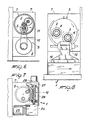
- the balancing device according to the invention is indicated by the number 1 .
- the spindles 2 and 3 include two counter-rotating spindles 2 and 3 supporting mills 4 with opposite cutting directions, corresponding to the rotation directions of spindles.
- the spindles 2 and 3 are also hold by an angularly oscillating support 5 , formed by a rotating cylindrical sleeve and rotatably engaged around an oscillating axle 6 coinciding with the symmetry axle of said sleeve and parallel to spindles 2 and 3.
- These last spindles are installed eccentrically and in angular positions different around the oscillating axle 6.
- the angularly oscillating support or sleeve 5 is housed within a bearing structure 7 , to which it is joined a sole motor unit 8 for the drive of both spindles.
- the spindles 2 and 3 are driven in opposite rotation directions by movement transmission means 9 , including, for example, a belt 10 and a spur gearing 11 .
- the sleeve 5 is driven in rotation by rotation means 12 suitable for orienting selectively the spindles 2 and 3 into operative positions with respect to a rotor 13 to be balanced.
- This last rotor can be moved along the axial direction by means of a slide 14 , for bringing the balancing planes 13a in substantially vertical alignment with one or other spindle 2 and 3 in operative positions.
- the bearing structure 7 can be moved along vertical direction, in a relative movement with respect to the slide 14, or also fixed in a vertical direction, as specified in the following.
- a first embodiment, shown in Figure 4, has rotation means 12 that includes at least a linear-type actuator 15 , for example a fluid-dynamic cylinder, whose rod is engaged to a rack element 16 meshing with a toothed gear krown 17 joined to the sleeve 5.
- a linear-type actuator 15 for example a fluid-dynamic cylinder, whose rod is engaged to a rack element 16 meshing with a toothed gear krown 17 joined to the sleeve 5.
- the Figure 4 shows two single-acting fluid-dynamic cylinders moving the sleeve 5 in opposed directions.
- the locking means 18 includes a couple of hooking elements 19 rotating around the pins 20 , and held against the sleeve 5 by an elastic force caused by springs 21 .
- the hooking elements 19 can be snap-joined into locking notches 22 provided into the sleeve 5 in areas suitable for locking this last sleeve in angular positions corresponding to the operative positions of spindles 2 and 3.
- a releasing element 23 formed by a linear fluid-dynamic actuator, acting selectively onto each hooking element 19, allows its releasing from the relevant locking notch 22.
- the just described first embodiment has the bearing structure 7 mobile in vertical direction in relative movement with respect to the slide 14, under the control of known means, for moving the mills 4 in vertical direction 4 and making the cuttings with the required cut depths.
- a second embodiment, shown in Figure 7, has rotating means 12 including a worm screw 24 , driven by a drive motor 25 with the meanly connected reduction unit 26, and a gear 27 joined to the sleeve 5 and operatively meshed with the worm screw 24.
- the stop of the worm screw 24 in any position establishes also a locking position for the rotation of the sleeve 5, as the worm screw-gear transmission is not reversible.
- the bearing structure 7 is fixed in vertical direction, as the same rotation of the sleeve 5 can adjust the position of mills 4 in vertical direction.
- the running of the device 1 occurs as follows.
- the rotor 13 to be balanced is mounted on the slide 14 and this slide is moved for adjusting a balancing plane 13a where the intervention of a mill 4 is foreseen.
- the mill 4 is moved in operative position by fluid-dynamic cylinders 15 that turn the sleeve 5. Then a hooking element 19 is snap-inserted into the related notch 22 allowing an angular exact positioning of the sleeve 5 and spindles in its operative position.
- bearing structure 7 moves vertically for allowing a milling according to the required cut depth.
- the releasing element 23, pressing against the hooking element 19, causes its output from the locking notch 22 and allows the rotation of the sleeve 5 for bringing the mill or mills of the other spindle to the operative position and carrying out the milling in the other balancing plane 13a.
- the worm screw 24 allows the operative reciprocating adjusting of spindles 2 and 3 of the relevant mills, but establishing for any position in which it is stopped also a rotation locking position of sleeve 5. Further the worm screw allows the mill to be directly moved in relation to the required cut depth. In fact, as shown in Figure 8, each mill is positioned in an initial operative position angularly spaced with respect to the vertical direction. The following rotation of the worm screw 24 causes a further angular traverse of the mills, in particular of the working mill, that approaching to the radial vertical position is lowered until the calculated cut depth.
Landscapes
- Engineering & Computer Science (AREA)
- Life Sciences & Earth Sciences (AREA)
- Mechanical Engineering (AREA)
- Wood Science & Technology (AREA)
- Forests & Forestry (AREA)
- Physics & Mathematics (AREA)
- General Physics & Mathematics (AREA)
- Manufacturing & Machinery (AREA)
- Power Engineering (AREA)
- Testing Of Balance (AREA)
- Manufacture Of Motors, Generators (AREA)
Applications Claiming Priority (2)
| Application Number | Priority Date | Filing Date | Title |
|---|---|---|---|
| IT2022090 | 1990-05-04 | ||
| IT20220A IT1240049B (it) | 1990-05-04 | 1990-05-04 | Dispositivo di equilibratura di rotori, particolarmente di indotti di motori elettrici |
Publications (2)
| Publication Number | Publication Date |
|---|---|
| EP0455127A1 true EP0455127A1 (de) | 1991-11-06 |
| EP0455127B1 EP0455127B1 (de) | 1993-07-21 |
Family
ID=11164868
Family Applications (1)
| Application Number | Title | Priority Date | Filing Date |
|---|---|---|---|
| EP91106622A Expired - Lifetime EP0455127B1 (de) | 1990-05-04 | 1991-04-24 | Vorrichtung zum Auswuchten von Rotoren, insbesondere Elektromotorenanker |
Country Status (4)
| Country | Link |
|---|---|
| EP (1) | EP0455127B1 (de) |
| JP (1) | JPH0592313A (de) |
| DE (1) | DE69100180T2 (de) |
| IT (1) | IT1240049B (de) |
Cited By (3)
| Publication number | Priority date | Publication date | Assignee | Title |
|---|---|---|---|---|
| EP0606052A1 (de) * | 1992-12-30 | 1994-07-13 | Ditta Bacci Paolino Di Giuseppe Bacci Di Agostino Bacci | Bearbeitungseinheit mit zwei Spindeln für Werkzeuge zum Bearbeiten von Holzwerkstücker oder dergleichen |
| EP0836087A2 (de) * | 1996-10-08 | 1998-04-15 | BALANCE SYSTEMS S.r.l. | Vorrichtung zum Auswuchten von Rotoren durch Materialentfernung |
| CN100436050C (zh) * | 2007-06-07 | 2008-11-26 | 浙江大学 | 全自动平衡机切削点自动定位装置 |
Families Citing this family (2)
| Publication number | Priority date | Publication date | Assignee | Title |
|---|---|---|---|---|
| IT201900004607A1 (it) | 2019-03-27 | 2020-09-27 | Balance Systems Srl | Dispositivo di misurazione degli squilibri |
| EP3974797B1 (de) | 2020-09-28 | 2023-09-06 | Balance Systems S.r.L. | Messgerät zur messung von unwuchten |
Citations (6)
| Publication number | Priority date | Publication date | Assignee | Title |
|---|---|---|---|---|
| DE872300C (de) * | 1948-11-19 | 1953-03-30 | Karl Emil Dipl-Ing Witzig | Bohrmaschine mit feststehender Tischflaeche zur Aufnahme der Werk-stuecke und mit schwenkbarem Revolverkopf zur Aufnahme mehrerer Werkzeugspindelkaesten |
| GB1033675A (en) * | 1962-01-25 | 1966-06-22 | Avery Ltd W & T | Device for unbalance correction on rotating bodies |
| DE1241153B (de) * | 1962-05-26 | 1967-05-24 | Schenck Gmbh Carl | Vorrichtung zum Ausgleichen von Unwuchten an rotierenden Koerpern, insbesondere an Elektromotorenankern |
| DE2638876A1 (de) * | 1976-08-28 | 1978-03-09 | Hofmann Gmbh & Co Kg Maschinen | Vorrichtung zum auswuchten von rotoren, insbesondere elektromotorenanker |
| DE2908272A1 (de) * | 1979-03-02 | 1980-09-04 | Hofmann Gmbh & Co Kg Maschinen | Verfahren und vorrichtung zum auswuchten von rotoren |
| DE3005423A1 (de) * | 1980-02-14 | 1981-08-20 | Dionys Hofmann GmbH, Maschinenfabrik, 7470 Albstadt | Vorrichtung zum auswuchten von rotoren, insbesondere elektromotorenanker |
-
1990
- 1990-05-04 IT IT20220A patent/IT1240049B/it active IP Right Grant
-
1991
- 1991-04-24 DE DE91106622T patent/DE69100180T2/de not_active Expired - Fee Related
- 1991-04-24 EP EP91106622A patent/EP0455127B1/de not_active Expired - Lifetime
- 1991-05-07 JP JP3101373A patent/JPH0592313A/ja active Pending
Patent Citations (6)
| Publication number | Priority date | Publication date | Assignee | Title |
|---|---|---|---|---|
| DE872300C (de) * | 1948-11-19 | 1953-03-30 | Karl Emil Dipl-Ing Witzig | Bohrmaschine mit feststehender Tischflaeche zur Aufnahme der Werk-stuecke und mit schwenkbarem Revolverkopf zur Aufnahme mehrerer Werkzeugspindelkaesten |
| GB1033675A (en) * | 1962-01-25 | 1966-06-22 | Avery Ltd W & T | Device for unbalance correction on rotating bodies |
| DE1241153B (de) * | 1962-05-26 | 1967-05-24 | Schenck Gmbh Carl | Vorrichtung zum Ausgleichen von Unwuchten an rotierenden Koerpern, insbesondere an Elektromotorenankern |
| DE2638876A1 (de) * | 1976-08-28 | 1978-03-09 | Hofmann Gmbh & Co Kg Maschinen | Vorrichtung zum auswuchten von rotoren, insbesondere elektromotorenanker |
| DE2908272A1 (de) * | 1979-03-02 | 1980-09-04 | Hofmann Gmbh & Co Kg Maschinen | Verfahren und vorrichtung zum auswuchten von rotoren |
| DE3005423A1 (de) * | 1980-02-14 | 1981-08-20 | Dionys Hofmann GmbH, Maschinenfabrik, 7470 Albstadt | Vorrichtung zum auswuchten von rotoren, insbesondere elektromotorenanker |
Cited By (4)
| Publication number | Priority date | Publication date | Assignee | Title |
|---|---|---|---|---|
| EP0606052A1 (de) * | 1992-12-30 | 1994-07-13 | Ditta Bacci Paolino Di Giuseppe Bacci Di Agostino Bacci | Bearbeitungseinheit mit zwei Spindeln für Werkzeuge zum Bearbeiten von Holzwerkstücker oder dergleichen |
| EP0836087A2 (de) * | 1996-10-08 | 1998-04-15 | BALANCE SYSTEMS S.r.l. | Vorrichtung zum Auswuchten von Rotoren durch Materialentfernung |
| EP0836087A3 (de) * | 1996-10-08 | 1999-03-10 | BALANCE SYSTEMS S.r.l. | Vorrichtung zum Auswuchten von Rotoren durch Materialentfernung |
| CN100436050C (zh) * | 2007-06-07 | 2008-11-26 | 浙江大学 | 全自动平衡机切削点自动定位装置 |
Also Published As
| Publication number | Publication date |
|---|---|
| JPH0592313A (ja) | 1993-04-16 |
| IT9020220A0 (it) | 1990-05-04 |
| DE69100180T2 (de) | 1993-11-04 |
| IT1240049B (it) | 1993-11-27 |
| IT9020220A1 (it) | 1991-11-04 |
| EP0455127B1 (de) | 1993-07-21 |
| DE69100180D1 (de) | 1993-08-26 |
Similar Documents
| Publication | Publication Date | Title |
|---|---|---|
| US2227410A (en) | Machine tool | |
| EP0455127B1 (de) | Vorrichtung zum Auswuchten von Rotoren, insbesondere Elektromotorenanker | |
| PT1520659E (pt) | Máquina de polir placas de pedra ou de mármore, compreendendo um gabarito | |
| GB2072067A (en) | Gear finishing machine | |
| US4926709A (en) | Motion transmitting systems for machinery & machine tools | |
| CN206653533U (zh) | 物料旋转式角度型材切割料车 | |
| US3595108A (en) | Apparatus for imparting a non-circular shape to an article | |
| CN110116343A (zh) | 一种剪板机用磨刀装置 | |
| US2561706A (en) | Diagonally traversing gear finishing machine | |
| US3960037A (en) | Machine for treating teeth of saw blades | |
| JPH03149152A (ja) | C―軸駆動機 | |
| CN211248844U (zh) | 一种激光切割用便携式滚轮夹具 | |
| US4446899A (en) | Double-sided tenoner | |
| EP0606052B1 (de) | Bearbeitungseinheit mit zwei Spindeln für Werkzeuge zum Bearbeiten von Holzwerkstücker oder dergleichen | |
| US4192363A (en) | Automatic profile-copying device | |
| EP0673715B1 (de) | Maschine zum bearbeiten einer glasplatte | |
| EP0607763A1 (de) | Anordnung zum dreieckigen Verstellen einer Fräserbefestigungsstange in einer Maschine zum Kantenpolieren von Platten aus Stein, Marmor oder ähnlichen Materialien | |
| EP0096831A1 (de) | Werkzeugmaschinen für zweiflächige Fräsarbeiten | |
| US2899737A (en) | Cutting apparatus | |
| CN220943355U (zh) | 一种铣床用刀具固定装置 | |
| CN217122388U (zh) | 一种型材四面钻铣加工装置 | |
| JPS6232045B2 (de) | ||
| EP0901882A2 (de) | Bearbeitungskopf für numerisch gesteuerte Werkzeugmaschinen | |
| US2234382A (en) | Machine for cutting or grinding spirally grooved cams | |
| DE945978C (de) | Werkzeugmaschine fuer die Bearbeitung ebener Flaechen |
Legal Events
| Date | Code | Title | Description |
|---|---|---|---|
| PUAI | Public reference made under article 153(3) epc to a published international application that has entered the european phase |
Free format text: ORIGINAL CODE: 0009012 |
|
| AK | Designated contracting states |
Kind code of ref document: A1 Designated state(s): CH DE ES FR GB LI |
|
| 17P | Request for examination filed |
Effective date: 19920410 |
|
| 17Q | First examination report despatched |
Effective date: 19920814 |
|
| GRAA | (expected) grant |
Free format text: ORIGINAL CODE: 0009210 |
|
| AK | Designated contracting states |
Kind code of ref document: B1 Designated state(s): CH DE ES FR GB LI |
|
| PG25 | Lapsed in a contracting state [announced via postgrant information from national office to epo] |
Ref country code: LI Effective date: 19930721 Ref country code: ES Free format text: THE PATENT HAS BEEN ANNULLED BY A DECISION OF A NATIONAL AUTHORITY Effective date: 19930721 Ref country code: CH Effective date: 19930721 |
|
| REF | Corresponds to: |
Ref document number: 69100180 Country of ref document: DE Date of ref document: 19930826 |
|
| REG | Reference to a national code |
Ref country code: CH Ref legal event code: PL |
|
| ET | Fr: translation filed | ||
| PLBE | No opposition filed within time limit |
Free format text: ORIGINAL CODE: 0009261 |
|
| STAA | Information on the status of an ep patent application or granted ep patent |
Free format text: STATUS: NO OPPOSITION FILED WITHIN TIME LIMIT |
|
| 26N | No opposition filed | ||
| PGFP | Annual fee paid to national office [announced via postgrant information from national office to epo] |
Ref country code: GB Payment date: 20010411 Year of fee payment: 11 Ref country code: FR Payment date: 20010411 Year of fee payment: 11 |
|
| PGFP | Annual fee paid to national office [announced via postgrant information from national office to epo] |
Ref country code: DE Payment date: 20010426 Year of fee payment: 11 |
|
| REG | Reference to a national code |
Ref country code: GB Ref legal event code: IF02 |
|
| PG25 | Lapsed in a contracting state [announced via postgrant information from national office to epo] |
Ref country code: GB Free format text: LAPSE BECAUSE OF NON-PAYMENT OF DUE FEES Effective date: 20020424 |
|
| PG25 | Lapsed in a contracting state [announced via postgrant information from national office to epo] |
Ref country code: DE Free format text: LAPSE BECAUSE OF NON-PAYMENT OF DUE FEES Effective date: 20021101 |
|
| GBPC | Gb: european patent ceased through non-payment of renewal fee |
Effective date: 20020424 |
|
| PG25 | Lapsed in a contracting state [announced via postgrant information from national office to epo] |
Ref country code: FR Free format text: LAPSE BECAUSE OF NON-PAYMENT OF DUE FEES Effective date: 20021231 |
|
| REG | Reference to a national code |
Ref country code: FR Ref legal event code: ST |