EP0454618A1 - Drafting roller unit - Google Patents
Drafting roller unit Download PDFInfo
- Publication number
- EP0454618A1 EP0454618A1 EP91810204A EP91810204A EP0454618A1 EP 0454618 A1 EP0454618 A1 EP 0454618A1 EP 91810204 A EP91810204 A EP 91810204A EP 91810204 A EP91810204 A EP 91810204A EP 0454618 A1 EP0454618 A1 EP 0454618A1
- Authority
- EP
- European Patent Office
- Prior art keywords
- godet
- drive motor
- circulation space
- roller unit
- stretching roller
- Prior art date
- Legal status (The legal status is an assumption and is not a legal conclusion. Google has not performed a legal analysis and makes no representation as to the accuracy of the status listed.)
- Granted
Links
- 238000004804 winding Methods 0.000 claims abstract description 9
- 230000006698 induction Effects 0.000 claims abstract description 5
- 238000010438 heat treatment Methods 0.000 claims description 3
- 238000012544 monitoring process Methods 0.000 claims description 3
- 230000002000 scavenging effect Effects 0.000 abstract 2
- 239000007789 gas Substances 0.000 description 17
- 238000001816 cooling Methods 0.000 description 6
- 239000002360 explosive Substances 0.000 description 3
- 238000000034 method Methods 0.000 description 3
- 238000002360 preparation method Methods 0.000 description 3
- IJGRMHOSHXDMSA-UHFFFAOYSA-N Atomic nitrogen Chemical compound N#N IJGRMHOSHXDMSA-UHFFFAOYSA-N 0.000 description 2
- 230000005540 biological transmission Effects 0.000 description 2
- 239000003795 chemical substances by application Substances 0.000 description 2
- 238000004880 explosion Methods 0.000 description 2
- 238000004519 manufacturing process Methods 0.000 description 2
- 239000000203 mixture Substances 0.000 description 2
- 239000000523 sample Substances 0.000 description 2
- 238000009423 ventilation Methods 0.000 description 2
- QVGXLLKOCUKJST-UHFFFAOYSA-N atomic oxygen Chemical compound [O] QVGXLLKOCUKJST-UHFFFAOYSA-N 0.000 description 1
- 230000001939 inductive effect Effects 0.000 description 1
- 238000009434 installation Methods 0.000 description 1
- 239000000463 material Substances 0.000 description 1
- 229910052757 nitrogen Inorganic materials 0.000 description 1
- 239000001301 oxygen Substances 0.000 description 1
- 229910052760 oxygen Inorganic materials 0.000 description 1
- 230000001681 protective effect Effects 0.000 description 1
- 238000010926 purge Methods 0.000 description 1
- 239000000565 sealant Substances 0.000 description 1
- 239000002904 solvent Substances 0.000 description 1
- 238000005406 washing Methods 0.000 description 1
Images

Classifications
-
- D—TEXTILES; PAPER
- D02—YARNS; MECHANICAL FINISHING OF YARNS OR ROPES; WARPING OR BEAMING
- D02J—FINISHING OR DRESSING OF FILAMENTS, YARNS, THREADS, CORDS, ROPES OR THE LIKE
- D02J13/00—Heating or cooling the yarn, thread, cord, rope, or the like, not specific to any one of the processes provided for in this subclass
- D02J13/005—Heating or cooling the yarn, thread, cord, rope, or the like, not specific to any one of the processes provided for in this subclass by contact with at least one rotating roll
-
- D—TEXTILES; PAPER
- D02—YARNS; MECHANICAL FINISHING OF YARNS OR ROPES; WARPING OR BEAMING
- D02J—FINISHING OR DRESSING OF FILAMENTS, YARNS, THREADS, CORDS, ROPES OR THE LIKE
- D02J1/00—Modifying the structure or properties resulting from a particular structure; Modifying, retaining, or restoring the physical form or cross-sectional shape, e.g. by use of dies or squeeze rollers
- D02J1/22—Stretching or tensioning, shrinking or relaxing, e.g. by use of overfeed and underfeed apparatus, or preventing stretch
- D02J1/224—Selection or control of the temperature during stretching
Definitions
- the present invention relates to a draw roll unit for draw-bobbin, spinning-draw-winder and draw-twisting machines with an inductively heatable godet according to the preamble of claim 1.
- the draw rollers are mostly driven by their own electric drive motor. Sparks can jump both in the motor and in the stretching roller, also called godet, within which windings for inductive heating are arranged. Simultaneously with the stretching process, it is common and often necessary to apply preparation agents to the yarn to be stretched. These preparation agents usually contain a proportion of volatile, easily flammable solvents. During the stretching process on the hot godet surface, the volatile, flammable parts of the preparation can evaporate from the yarn and together with the room air form a flammable, possibly explosive mixture that can be ignited by sparking in the stretch roller unit or in the drive motor.
- the invention seeks to remedy this.
- the invention as characterized in the claims, solves the problem of creating a stretching roller unit which can be used in potentially explosive areas.
- it is possible to flood the stretching roller unit with an incombustible gas without changing its dimensions Need to become.
- This enables interchangeability with conventional units.
- This goal is achieved in that the incombustible gas is introduced into the fixed, drive-side part of the unit and runs through one or more circulation spaces from the drive side through the drive motor and / or the stretching roller and sweeps over all unit parts that may come into being due to sparking.
- the small cross-section of the annular gap between the godet surface and the housing means that a constant overpressure can be maintained in the latter even with a very small amount of gas supplied to the unit.
- the small amount of gas required has no influence on the temperature at the godet surface;
- the gas flowing through increases the cooling in the drive motor.
- the cooling for the stator part of the electric motor takes place independently of the flow through the central part of the unit.
- the engine cooling which requires a large amount of air, can be done with room air, since no sparks can occur in the cooling area.
- No sealant is required between standing and rotating parts for the access of the protective gas, since the supply takes place in the housing enclosing the motor and / or the godet.
- there are no high demands on the tightness of this housing since small losses can be borne by the low overpressure required within the circulation space. The low overpressure is sufficient because the gas only has to prevent the entry of oxygen from the environment.
- the two figures show a longitudinal section through a stretching roller unit, in which all parts that are not essential to the invention are omitted or only shown schematically.
- the stretching roller unit 1 according to the invention according to FIG. 1 is fixed rigidly or elastically in the area of the drive motor 3 on a bearing frame 5.
- the shaft 7 of the drive motor 3 projects beyond the motor housing 23 and carries on one side a first bearing 11 and on the other side a second bearing 13 and the stretching roller or godet 15. The latter is pushed onto the conical end 17 of the shaft 7 and with it screwed.
- the rotor 19 is shown between the two bearings 11 and 13.
- the stator 21, the motor housing 23 and the cooling fins 25 are visible outside the rotor 19.
- a housing 27 Connected to the motor 3 is a housing 27 which receives the electrical transmission elements and which is closed on the back by a screwed-on terminal housing 29.
- a supply line 31 for supplying gas is let into the terminal housing 29.
- the cup-shaped godet 15 completely encloses the end 33 of the shaft 7.
- the sleeve 37 has an inductor flange 39 on the drive motor side.
- a cover collar 41 the bore diameter of which is only slightly larger than the outer diameter of the godet 15, which penetrates the cover collar 41, is attached to the drive motor 3.
- the cover collar 41 is preferably made of a softer material than the godet 15, so that when the unit 1 runs in during commissioning when the cover collar 41 touches the godet surface 43, the latter is not damaged and a minimal annular gap 45 can be generated.
- the shaft 7 is penetrated by an axial bore 47.
- This bore 47 receives the feeds for the temperature probes 49 installed in the godet 15 for the temperature improvement of the godet surface 43.
- the signals of the rotating probes 49 are transmitted to the fixed electronics 51 without contact in the housing 27.
- a cover 53 in the form of a hollow cylinder jacket extends from the housing 27 over the motor housing 23 and encloses all the underlying parts of the motor 3 and the electronics 51.
- a cooling air supply connection 55 connects the ventilation space 57 formed by the cover 53 and the surface of the motor housing 23 and the housing 27. The air exits from ventilation space 57 in area Y (arrow 58).
- the feed line 31 in the terminal housing 29 forms the entrance to a circulation space 59 which begins in the terminal housing 29 and ends at the annular gap 45.
- the circulation space 59 comprises the entire area of the electronics 51, in which the signal is transferred from rotating to stationary parts, and the pressure monitor 71, and extends further, partly in bores 52, partly through slots into the drive motor 3.
- the circulation space 59 extends further to the area of the bearing 13. After a slight narrowing due to recesses and / or one or more bores 61, the circulation space 59 continues within the godet 15, first in a disk-shaped space running radially inward 63 to the shaft 7.
- the space 59 extends as an annular gap 65 along the shaft end 33 to the end face 67 of the godet 15.
- the circulation space 59 is again disk-shaped and then sits radially outside in a cylindrical gap 69 in the direction of the drive side and ends at the gap 45 between de r godet surface 43 and the cover collar 41.
- the described circulation space 59 forms a closed jacket around all possible spark sources present on the stretching roller assembly 1.
- the parts of the electronics 51 could be arranged in a rotating / fixed manner outside the circulation space 59 in a separate closed space.
- non-flammable gas is used for a predetermined time, for example three minutes, before start-up let in.
- the mode of operation can be determined using one or more pressure gauges that are connected to the circulation space the rinse during the stretching process by continuously monitoring the overpressure.
- Room air can be introduced through the air supply connection 55, even if it contains flammable gases, and the drive motor 3 can be cooled.
- the rinse, which is supplied through line 31, can be obtained from a bottle or from the atmosphere outside the working area of the stretching roller unit 1.
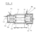
- FIG. 2 apparently shows such a stretching roller unit, which has two separate circulation spaces for the drive motor 103 and the stretching roller 115.
- a bearing with the two bearings 111 and 113 is located in the center.
- the drive motor 103 is arranged on the left side of the bearing and the godet 115 on the right side.
- gas is fed into the circulation space 159 through the line 131. At the other end of engine 103, the gas can escape again through a gap 145.
- Gas is fed through a line 180 into a circulation space 183 in the godet 115 and can leave the godet 115 again through a gap 181.
- the two feed lines 131 and 180 as well as the two outlet areas 145 and 181 can each be connected to a common feed or drain line (no illustration).
Landscapes
- Engineering & Computer Science (AREA)
- Textile Engineering (AREA)
- Yarns And Mechanical Finishing Of Yarns Or Ropes (AREA)
- Spinning Methods And Devices For Manufacturing Artificial Fibers (AREA)
- Forwarding And Storing Of Filamentary Material (AREA)
Abstract
Description
Die vorliegende Erfindung bezieht sich auf ein Streckrollenaggregat für Streckspul-, Spinnstreckspul- und Streckzwirnmaschinen mit einer induktiv beheizbaren Galette gemäss Oberbegriff des Patentanspruches 1.The present invention relates to a draw roll unit for draw-bobbin, spinning-draw-winder and draw-twisting machines with an inductively heatable godet according to the preamble of
Bei den Streckspul-, Spinnstreckspul- und Streckzwirnmaschinen werden die Streckrollen meistens von einem eigenen elektrischen Antriebsmotor angetrieben. Sowohl im Motor als auch in der Streckrolle, auch Galette genannt, innerhalb welcher Wicklungen für eine Induktivheizung angeordnet sind, können Funken springen.
Gleichzeitig mit dem Streckvorgang ist es üblich und oft nötig, auf das zu verstreckende Garn Präparationsmittel aufzubringen. Diese Präparationsmittel enthalten meistens einen Anteil von leichtflüchtigen, leicht brennbaren Lösungsmitteln. Während des Streckvorganges auf der heissen Galettenoberfläche können die leichtflüchtigen, brennbaren Anteile der Präparationsmittel aus dem Garn verdunsten und zusammen mit der Raumluft ein brennbares, allenfalls explosives Gemisch bilden, das durch Funkenbildung im Streckrollenaggregat oder im Antriebsmotor entzündet werden kann.In the draw-bobbin, spinning-draw-bobbin and draw-twisting machines, the draw rollers are mostly driven by their own electric drive motor. Sparks can jump both in the motor and in the stretching roller, also called godet, within which windings for inductive heating are arranged.
Simultaneously with the stretching process, it is common and often necessary to apply preparation agents to the yarn to be stretched. These preparation agents usually contain a proportion of volatile, easily flammable solvents. During the stretching process on the hot godet surface, the volatile, flammable parts of the preparation can evaporate from the yarn and together with the room air form a flammable, possibly explosive mixture that can be ignited by sparking in the stretch roller unit or in the drive motor.
Um die Explosisionsgefahr zu verhindern, ist es denkbar, anstelle eines gewöhnlichen Antriebsmotors eine im Handel erhältliche explosionsgeschützte Ausführung für den Antrieb der Streckrolle zu verwenden. Solche explosionsgeschützte Antriebsmotoren sind wesentlich teurer als ungeschützte und verursachen zudem infolge grösserer Abmessungen Raumprobleme, wenn sie nachträglich in bestehende Streckspulmaschinen eingebaut werden müssen. Im weiteren müssen dann auch sämtliche Ueberwachungseleinente explosionsgeschützt hergestellt und für die Streckrolle ein vom Motor unabhängiger Explosionsschutz gewährleistet sein.To prevent the risk of explosion, it is conceivable to use a commercially available explosion-proof version for driving the stretching roller instead of a conventional drive motor. Such explosion-proof drive motors are much more expensive than unprotected ones and, due to their larger dimensions, also cause space problems if they have to be retrofitted into existing stretch winding machines. Furthermore, all monitoring elements must then be manufactured in an explosion-proof manner and explosion protection independent of the motor must be guaranteed for the stretching roller.
Hier will die Erfindung Abhilfe schaffen.
Die Erfindung, wie sie in den Ansprüchen gekennzeichnet ist, löst die Aufgabe, ein Streckrollenaggregat zu schaffen, welches in explosionsgefährdeten Räumen verwendet werden kann.
Es gelingt mit der erfindungsgemässen Ausbildung, das Streckrollenaggregat mit einem unbrennbaren Gas zu durchfluten, ohne dass dessen Abmessungen verändert werden müssen. Dies ermöglicht eine Austauschbarkeit mit den herkömmlichen Aggregaten.
Erreicht wird dieses Ziel dadurch, dass das unbrennbare Gas am feststehenden, antriebsseitigen Teil des Aggregates in dieses eingebracht und durch einen oder mehrere Zirkulationsräume von der Antriebsseite durch den Antriebsmotor und/oder die Streckrolle hindurch verläuft und sämtliche durch eine Funkenbildung in Frage kommende Aggregatteile überstreicht. Der geringe Querschnitt des Ringspaltes zwischen der Galettenoberfläche und dem Gehäuse bewirkt, dass bereits bei einer sehr kleinen, dem Aggregat zugeführten Gasmenge im letzteren ein konstanter Ueberdruck aufrechterhalten werden kann. Die geringe notwendige Gasmenge hat keinen Einfluss auf die Temperatur an der Galettenoberfläche; im Antriebsmotor erhöht das durchfliessende Gas zusätzlich die Kühlung. Die Kühlung für den Statorteil des Elektromotors erfolgt unabhängig von der Durchflutung des zentralen Teiles des Aggregates. Die eine hohe Luftmenge erforderlich machende Motorkühlung kann mit Raumluft erfolgen, da im Kühlbereich keine Funken entstehen können.
Von der Gasspülung können nicht nur die Wicklung des Elektromotors und jene der Induktionsheizung erfasst werden, sondern es ist gleichzeitig und ohne wesentlichen Mehraufwand möglich, auch sämtliche Steuerorgane innerhalb eines einzigen oder in nach Aggregatsteilen aufgeteilten Zirkulationsraumes unterzubringen. Für den Zutritt des Schutzgases sind keine Dichtungsmittel zwischen stehenden und rotierenden Teilen notwendig, da die Zufuhr in das den Motor und/oder die Galette einschliessende Gehäuse erfolgt. Auch sind an die Dichtigkeit dieses Gehäuses keine hohen Anforderungen zu stellen, da durch den geringen notwendigen Ueberdruck innerhalb des Zirkulationsraumes kleine Verluste tragbar sind. Der geringe Überdruck reicht aus, weil das Gas nur den Zutritt von Sauerstoff aus der Umgebung zu verhindern hat.The invention seeks to remedy this.
The invention, as characterized in the claims, solves the problem of creating a stretching roller unit which can be used in potentially explosive areas.
With the design according to the invention, it is possible to flood the stretching roller unit with an incombustible gas without changing its dimensions Need to become. This enables interchangeability with conventional units.
This goal is achieved in that the incombustible gas is introduced into the fixed, drive-side part of the unit and runs through one or more circulation spaces from the drive side through the drive motor and / or the stretching roller and sweeps over all unit parts that may come into being due to sparking. The small cross-section of the annular gap between the godet surface and the housing means that a constant overpressure can be maintained in the latter even with a very small amount of gas supplied to the unit. The small amount of gas required has no influence on the temperature at the godet surface; The gas flowing through increases the cooling in the drive motor. The cooling for the stator part of the electric motor takes place independently of the flow through the central part of the unit. The engine cooling, which requires a large amount of air, can be done with room air, since no sparks can occur in the cooling area.
Not only can the winding of the electric motor and that of the induction heating be detected by the gas purging, but it is also possible at the same time and without significant additional effort to accommodate all of the control elements within a single or in a circulation space divided into unit parts. No sealant is required between standing and rotating parts for the access of the protective gas, since the supply takes place in the housing enclosing the motor and / or the godet. Also, there are no high demands on the tightness of this housing, since small losses can be borne by the low overpressure required within the circulation space. The low overpressure is sufficient because the gas only has to prevent the entry of oxygen from the environment.
Die Erfindung wird anhand zweier bevorzugter Ausführungsformen näher beschrieben.
Es zeigen
Figur 1 einen Querschnitt durch ein Streckrollenaggregat mit einem gemeinsamen Zirkuationsraum und- Figur 2 einen Querschnitt durch ein Streckrollenaggregat mit getrennten Zirkulationsräumen für die einzelnen Aggregatsteile
Show it
- 1 shows a cross section through a stretching roller unit with a common circulation space and
- Figure 2 shows a cross section through a stretching roller unit with separate circulation spaces for the individual unit parts
Die beiden Figuren zeigen einen Längsschnitt durch ein Streckrollenaggregat, bei dem alle für die Erfindung nicht wesentlichen Teile weggelassen oder nur schematisch dargestellt sind. Das erfindungsgemässe Streckrollenaggregate 1 nach Figur 1 ist im Bereich des Antriebsmotors 3 auf einem Lagerrahmen 5 starr oder elastisch befestigt. Die Welle 7 des Antriebsmotors 3 überragt das Motorgehäuse 23 und trägt auf der einen Seite ein erstes Lager 11 und auf der anderen Seite ein zweites Lager 13 sowie die Streckrolle oder Galette 15. Letztere ist auf das konische Ende 17 der Welle 7 aufgeschoben und mit dieser verschraubt. Zwischen den beiden Lagern 11 und 13, ist der Rotor 19 dargestellt. Ausserhalb des Rotors 19 sind der Stator 21, das Motorgehäuse 23 und die Kühlrippen 25 sichtbar.
Mit dem Motor 3 verbunden ist ein die elektrischen Uebertragungsorgane aufnehmendes Gehäuse 27, das auf der Rückseite durch ein aufgeschraubtes Klemmengehäuse 29 verschlossen ist. Im Klemmengehäuse 29 ist eine Zuleitung 31 zum Zuführen von Gas eingelassen.
Die becherförmig ausgebildete Galette 15 umschliesst das Ende 33 der Welle 7 vollständig. Im Innern der Galette 15 ist das Paket der Induktionswicklungen 35, welche von einer feststehenden, mit dem Antriebsmotor 3 verschraubten, zylindrischen Hülse 37 getragen werden, sichtbar. Die Hülse 37 weist antriebsmotorseitig einen Induktorflansch 39 auf. Ein Abdeckkragen 41, dessen Bohrungsdurchmesser nur geringfügig grösser ist als der Aussendurchmesser der Galette 15, die den Abdeckkragen 41 durchdringt, ist am Antriebsmotor 3 befestigt. Vorzugsweise ist der Abdeckkragen 41 aus einem weicheren Material hergestellt als die Galette 15, damit beim Einlaufen des Aggregates 1 bei der Inbetriebnahme bei Berührung des Abdeckkragens 41 durch die Galettenobefläche 43 die letztere nicht beschädigt und ein minimaler Ringspalt 45 erzeugbar ist.The two figures show a longitudinal section through a stretching roller unit, in which all parts that are not essential to the invention are omitted or only shown schematically. The
Connected to the motor 3 is a
The cup-
Die Welle 7 wird von einer axialen Bohrung 47 durchdrungen. Diese Bohrung 47 nimmt die Zuführungen für die in der Galette 15 eingebauten Temperatursonden 49 für die Temperaturinessung der Galettenobefläche 43 auf. Die Signalübergabe der mitdrehenden Sonden 49 an die feststehende Elektronik 51 erfolgt berührungsfrei im Gehäuse 27.The
Vom Gehäuse 27 führt eine hohlzylindermantelförmige Abdeckung 53 über das Motorgehäuse 23 und umschliesst sämtliche darunterliegende Teile des Motors 3 und der Elektronik 51. Ein Kühlluft-Zufuhrstutzen 55 verbindet den durch die Abdeckung 53 und die Oberfläche des Motorgehäuses 23 sowie des Gehäuses 27 gebildeten Lüftungsraum 57. Der Luftaustritt aus dem Lüftungsraum 57 erfolgt im Bereich Y (Pfeil 58).A
Die Zuleitung 31 im Klemmengehäuse 29 bildet den Eingang zu einem im Klemmengehäuse 29 beginnenden und am Ringspalt 45 endenden Zirkulationsraum 59. Beginnend am Boden des Klemmengehäuses 29 umfasst der Zirkulationsraum 59 den gesamten Bereich der Elektronik 51, in welchem die Signalübergabe von drehenden zu feststehenden Teilen erfolgt sowie der Drucküberwachung 71 und zieht sich weiter, teils in Bohrungen 52, teils durch Schlitze hinein in den Antriebsmotor 3. Durch einen ringförmigen Raum zwischen dem Stator 21 und dem Motorgehäuse 23 zieht sich der Zirkulationsraum 59 weiter zum Bereich des Lagers 13. Nach einer leichten Verengung durch Aussparungen und/oder eine oder mehrere Bohrungen 61 setzt sich der Zirkulationsraum 59 fort innerhalb der Galette 15, und zwar zuerst radial nach innen verlaufend in einen scheibenförmigen Raum 63 bis hin zur Welle 7. Von dort erstreckt sich der Raum 59 als Ringspalt 65 entlang dem Wellenende 33 zur Stirnseite 67 der Galette 15. Im Bereich des Wellenendes 17 ist der Zirkulationsraum 59 wieder scheibenförmig ausgebildet und setzt sich radial ausserhalb dann in einem zylindrischen Spalt 69 in Richtung auf die Antriebsseite fort und endet beim Spalt 45 zwischen der Galettenoberfläche 43 und dem Abdeckkragen 41. Der beschriebene Zirkulationsraum 59 bildet einen geschlossenen Mantel um sämtliche am Streckrollenaggregat 1 vorhandenen möglichen Funkenquellen.The
Selbstverständlich könnten die Teile der Elektronik 51 mit Ausnahme der Uebertragungsstellen rotierend/feststehend ausserhalb des Zirkulationsraumes 59 in einem separaten verschlossenen Raum angeordnet sein. Dies würde aber eine Vielzahl von luftdicht zu verschliessende Durchbrüche bedingen. Es bestünde auch die Möglichkeit, die funkenerzeugenden Elemente in explosionsgeschützter Bauweise herzustellen. Dies verursacht jedoch um ein Vielfaches höhere Kosten.Of course, with the exception of the transmission points, the parts of the
Während des Betriebes des Streckrollenaggregates 1 wird durch die Zuleitung 31 Stickstoff, saubere Luft oder ein anderes nicht brennbares Gas in den Zirkulationsraum 59 eingeleitet. Dieses füllt den gesamten oben beschriebenen Raum auf und durchspült diesen, bis es entlang dem Spalt 45 nach aussen in den Raum austritt oder, falls eine entsprechende Verbindungsleitung vorgesehen wird, in einen Raum ausserhalb des Aufstellungsortes des Aggregates. Durch die geringe Breite des Ringspaltes 45 kann bereits durch eine kleine eingangs zugeführte Menge im Innern des Zirkulationsraumes 59 ein Druck aufgebaut werden und so der Zutritt von allenfalls explosivem oder brennbarem Gas aus der Umgebung zu funkenerzeugenden Teilen im Innern des Aggregates 1 sicher verhindert werden. Damit nach einem Stillstand oder einer Erstinbetriebnahme das im Innern befindliche, bei der Herstellung oder beim Stillstand eindiffundierte Gas, dessen Zusammensetzung unbekannt ist, aus dem Zirkulationsraum 59 sicher entfernt werden kann, wird jeweils vor Inbetriebnahme während einer vorgebbaren Zeit, z.B. drei Minuten, unbrennbares Gas eingelassen. Mittels eines oder mehrerer Manometer, die mit dem Zirkulationsraum in Verbindung stehen, kann die Funktionsweise der Spülung während des Streckprozesses durch Messung des Ueberdruckes kontinuierlich überwacht werden.During operation of the
Durch den Luftzufuhrstutzen 55 kann Raumluft, auch wenn diese feuergefährliche Gase enthält, eingeführt und der Antriebsmotor 3 gekühlt werden.
Die Spülung, welche durch die Leitung 31 zugeführt wird, kann aus einer Flasche oder aus der Atmosphäre ausserhalb des Arbeitsraumes des Streckrollenaggregates 1 bezogen werden.Room air can be introduced through the
The rinse, which is supplied through
Selbstverständlich könnte anstelle eines einzigen, das gesamte Aggregat umspülenden Zirkulationsraumes 59 auch eine Aufteilung in mehrere, separat gespeiste Abschnitte, z.B. Antriebsmotor und Galette, vorgesehen werden. Figur 2 zeigt scheinatisch ein solches Streckrollenaggregat, das zwei getrennte Zirkulationsräume für den Antriebsmotor 103 und die Streckrolle 115 aufweist. Im Zentrum befindet sich eine Lagerung mit den zwei Lagern 111 und 113. Auf der linken Seite der Lagerung ist der Antriebsmotor 103 und auf der rechten Seite die Galette 115 angeordnet. Analog zum Beispiel gemäss Figur 1 wird Gas durch die Leitung 131 in den Zirkulationsraum 159 eingespiesen. Am anderen Ende des Motors 103 kann das Gas durch einen Spalt 145 wieder austreten.
Durch eine Leitung 180 wird Gas in einen Zirkulationsraum 183 in der Gallette 115 eingespeist und kann durch einen Spalt 181 die Galette 115 wieder verlassen. Die beiden Speiseleitungen 131 und 180 sowie die beiden Austrittsbereiche 145 und 181 können jweils an eine gemeinsamen Speise- bzw. Abzugsleitung angeschlossen sein (keine Abb.)Of course, instead of a
Gas is fed through a
Claims (5)
Applications Claiming Priority (2)
| Application Number | Priority Date | Filing Date | Title |
|---|---|---|---|
| CH1433/90 | 1990-04-26 | ||
| CH143390 | 1990-04-26 |
Publications (2)
| Publication Number | Publication Date |
|---|---|
| EP0454618A1 true EP0454618A1 (en) | 1991-10-30 |
| EP0454618B1 EP0454618B1 (en) | 1994-05-18 |
Family
ID=4210350
Family Applications (1)
| Application Number | Title | Priority Date | Filing Date |
|---|---|---|---|
| EP91810204A Expired - Lifetime EP0454618B1 (en) | 1990-04-26 | 1991-03-22 | Drafting roller unit |
Country Status (4)
| Country | Link |
|---|---|
| US (1) | US5324905A (en) |
| EP (1) | EP0454618B1 (en) |
| JP (1) | JPH04228643A (en) |
| DE (1) | DE59101640D1 (en) |
Cited By (3)
| Publication number | Priority date | Publication date | Assignee | Title |
|---|---|---|---|---|
| US5763859A (en) * | 1993-06-04 | 1998-06-09 | Maschinenfabrik Rieter Ag | Induction heating draw roller with vibration damping |
| WO2008098996A1 (en) * | 2007-02-16 | 2008-08-21 | Oerlikon Textile Gmbh & Co. Kg | Galette |
| CN105543985A (en) * | 2016-01-29 | 2016-05-04 | 佛山轻子精密测控技术有限公司 | Gap-adjustable electrostatic-spinning nozzle and array-type spinning system |
Families Citing this family (8)
| Publication number | Priority date | Publication date | Assignee | Title |
|---|---|---|---|---|
| KR100461685B1 (en) * | 1996-07-01 | 2005-07-07 | 바마크 악티엔게젤샤프트 | Godet device for guiding and driving |
| DE19726258C2 (en) * | 1996-07-01 | 2001-10-04 | Barmag Barmer Maschf | Godet unit for guiding and conveying a thread |
| CH692954A5 (en) * | 1997-11-28 | 2002-12-31 | Barmag Barmer Maschf | Galette for conveying and guiding a running synthetic thread. |
| CN1272153A (en) * | 1998-05-28 | 2000-11-01 | 巴马格股份公司 | Godet roll for guiding, heating and conveying thread |
| DE19843990C1 (en) * | 1998-09-25 | 1999-08-19 | Dienes Apparatebau Gmbh | Heated godet roller assembly for processing synthetic filaments and yarns |
| JP5269546B2 (en) * | 2008-10-30 | 2013-08-21 | 株式会社ブリヂストン | Conductive roller |
| DE102017009256A1 (en) * | 2017-10-05 | 2019-04-11 | Rpe Technologies Gmbh | yarn treating |
| DE102019134639B4 (en) * | 2019-12-17 | 2021-07-29 | Stc Spinnzwirn Gmbh | Galette |
Citations (2)
| Publication number | Priority date | Publication date | Assignee | Title |
|---|---|---|---|---|
| FR1018863A (en) * | 1949-04-06 | 1953-01-14 | Westinghouse Electric Corp | Explosion-proof dynamo-electric machine |
| EP0349829A2 (en) * | 1988-06-30 | 1990-01-10 | Maschinenfabrik Rieter Ag | Roller with a large rotating speed range |
Family Cites Families (9)
| Publication number | Priority date | Publication date | Assignee | Title |
|---|---|---|---|---|
| US2761941A (en) * | 1953-06-01 | 1956-09-04 | Ardichvili Georges | Roller temperature modifying apparatus |
| US3602746A (en) * | 1970-03-23 | 1971-08-31 | John C St Clair | Motor-generator with hollow plastic rotor rotating in high pressure chamber |
| US3879594A (en) * | 1972-09-29 | 1975-04-22 | Terence Graham Shillito | Temperature measurement and control of rotating surfaces |
| CH573992A5 (en) * | 1973-11-02 | 1976-03-31 | Rieter Ag Maschf | |
| DE2647540C2 (en) * | 1976-10-21 | 1978-10-12 | Barmag Barmer Maschinenfabrik Ag, 5630 Remscheid | Induction heatable godet |
| DE3033482C2 (en) * | 1980-09-05 | 1983-06-23 | Kleinewefers Gmbh, 4150 Krefeld | Electromagnetic heating roller |
| DE3147829A1 (en) * | 1981-12-03 | 1983-06-16 | Robert Bosch Gmbh, 7000 Stuttgart | ELECTRIC COLLECTOR MACHINE, IN PARTICULAR AS A DRIVE MOTOR FOR VEHICLES |
| SE457183B (en) * | 1984-10-05 | 1988-12-05 | Asea Ab | synchronous |
| DE3763696D1 (en) * | 1986-03-03 | 1990-08-23 | Teijin Seiki Co Ltd | COOLING DEVICE FOR THE BEARINGS OF A HEATING ROLL. |
-
1991
- 1991-03-22 DE DE59101640T patent/DE59101640D1/en not_active Expired - Fee Related
- 1991-03-22 EP EP91810204A patent/EP0454618B1/en not_active Expired - Lifetime
- 1991-04-25 JP JP3095078A patent/JPH04228643A/en active Pending
- 1991-04-26 US US07/692,118 patent/US5324905A/en not_active Expired - Fee Related
Patent Citations (2)
| Publication number | Priority date | Publication date | Assignee | Title |
|---|---|---|---|---|
| FR1018863A (en) * | 1949-04-06 | 1953-01-14 | Westinghouse Electric Corp | Explosion-proof dynamo-electric machine |
| EP0349829A2 (en) * | 1988-06-30 | 1990-01-10 | Maschinenfabrik Rieter Ag | Roller with a large rotating speed range |
Cited By (3)
| Publication number | Priority date | Publication date | Assignee | Title |
|---|---|---|---|---|
| US5763859A (en) * | 1993-06-04 | 1998-06-09 | Maschinenfabrik Rieter Ag | Induction heating draw roller with vibration damping |
| WO2008098996A1 (en) * | 2007-02-16 | 2008-08-21 | Oerlikon Textile Gmbh & Co. Kg | Galette |
| CN105543985A (en) * | 2016-01-29 | 2016-05-04 | 佛山轻子精密测控技术有限公司 | Gap-adjustable electrostatic-spinning nozzle and array-type spinning system |
Also Published As
| Publication number | Publication date |
|---|---|
| EP0454618B1 (en) | 1994-05-18 |
| US5324905A (en) | 1994-06-28 |
| JPH04228643A (en) | 1992-08-18 |
| DE59101640D1 (en) | 1994-06-23 |
Similar Documents
| Publication | Publication Date | Title |
|---|---|---|
| EP0454618B1 (en) | Drafting roller unit | |
| DE2046810C3 (en) | Twin-shaft gas turbine plant | |
| DE2412584A1 (en) | LUBRICATION SYSTEM | |
| DE2728382A1 (en) | GAS TURBINE | |
| DE69406831T2 (en) | Roll with drive motor arranged inside the roll shell | |
| EP0039938B1 (en) | Asymmetrical false twist texturing machine | |
| DE2000869A1 (en) | Method and device for heating gases by means of an electric arc | |
| DE2040940C3 (en) | Lubricating device for a bearing arrangement | |
| EP0162941B1 (en) | Process for monitoring the burning temperature of a firing kiln in the laquered -thread production, and kiln therefor | |
| DE19720916C5 (en) | Planetary roller extruder with stop ring | |
| EP0939152B1 (en) | Procedure for producing a twisted yarn in an integrated spinning and twisting process using the two-for-one principle, as well as a device to carry out the procedure | |
| DE2828689C2 (en) | Electric machine with an axial fan | |
| DD156923A5 (en) | METHOD AND DEVICE FOR OPERATING A DEVICE FOR THE GLAETTEN MOISTURE WAIST STICK | |
| DE1803060C3 (en) | Method and device for crimping textile strand material | |
| DE3915676C2 (en) | Incinerator | |
| DE8801028U1 (en) | High pressure cleaning device | |
| DE2261459A1 (en) | DEVICE FOR SPIN-DRAWING SYNTHETIC FIBERS | |
| DE60201234T2 (en) | Paper web feed in rotary printing machine | |
| EP0253216A2 (en) | Apparatus for manufacturing plastic sheets | |
| DE29605198U1 (en) | Dryer section | |
| DE2056190C3 (en) | Nozzle dryer for continuously running web-shaped material | |
| DE2034415C3 (en) | Crusher | |
| DE2324611C3 (en) | Water-cooled roll for paper machines | |
| DE423484C (en) | Axial internal combustion turbine | |
| DE9104578U1 (en) | Gas supply system |
Legal Events
| Date | Code | Title | Description |
|---|---|---|---|
| PUAI | Public reference made under article 153(3) epc to a published international application that has entered the european phase |
Free format text: ORIGINAL CODE: 0009012 |
|
| AK | Designated contracting states |
Kind code of ref document: A1 Designated state(s): CH DE FR GB IT LI |
|
| 17P | Request for examination filed |
Effective date: 19920225 |
|
| 17Q | First examination report despatched |
Effective date: 19930816 |
|
| GRAA | (expected) grant |
Free format text: ORIGINAL CODE: 0009210 |
|
| AK | Designated contracting states |
Kind code of ref document: B1 Designated state(s): CH DE FR GB IT LI |
|
| REF | Corresponds to: |
Ref document number: 59101640 Country of ref document: DE Date of ref document: 19940623 |
|
| ITF | It: translation for a ep patent filed | ||
| GBT | Gb: translation of ep patent filed (gb section 77(6)(a)/1977) |
Effective date: 19940712 |
|
| ET | Fr: translation filed | ||
| PGFP | Annual fee paid to national office [announced via postgrant information from national office to epo] |
Ref country code: DE Payment date: 19950211 Year of fee payment: 5 |
|
| PGFP | Annual fee paid to national office [announced via postgrant information from national office to epo] |
Ref country code: GB Payment date: 19950213 Year of fee payment: 5 Ref country code: CH Payment date: 19950213 Year of fee payment: 5 |
|
| PGFP | Annual fee paid to national office [announced via postgrant information from national office to epo] |
Ref country code: FR Payment date: 19950217 Year of fee payment: 5 |
|
| PLBE | No opposition filed within time limit |
Free format text: ORIGINAL CODE: 0009261 |
|
| STAA | Information on the status of an ep patent application or granted ep patent |
Free format text: STATUS: NO OPPOSITION FILED WITHIN TIME LIMIT |
|
| 26N | No opposition filed | ||
| PG25 | Lapsed in a contracting state [announced via postgrant information from national office to epo] |
Ref country code: GB Effective date: 19960322 |
|
| PG25 | Lapsed in a contracting state [announced via postgrant information from national office to epo] |
Ref country code: LI Effective date: 19960331 Ref country code: CH Effective date: 19960331 |
|
| GBPC | Gb: european patent ceased through non-payment of renewal fee |
Effective date: 19960322 |
|
| REG | Reference to a national code |
Ref country code: CH Ref legal event code: PL |
|
| PG25 | Lapsed in a contracting state [announced via postgrant information from national office to epo] |
Ref country code: FR Effective date: 19961129 |
|
| PG25 | Lapsed in a contracting state [announced via postgrant information from national office to epo] |
Ref country code: DE Effective date: 19961203 |
|
| REG | Reference to a national code |
Ref country code: FR Ref legal event code: ST |
|
| PG25 | Lapsed in a contracting state [announced via postgrant information from national office to epo] |
Ref country code: IT Free format text: LAPSE BECAUSE OF NON-PAYMENT OF DUE FEES;WARNING: LAPSES OF ITALIAN PATENTS WITH EFFECTIVE DATE BEFORE 2007 MAY HAVE OCCURRED AT ANY TIME BEFORE 2007. THE CORRECT EFFECTIVE DATE MAY BE DIFFERENT FROM THE ONE RECORDED. Effective date: 20050322 |