EP0454439A1 - Pompe-injecteur de combustible - Google Patents
Pompe-injecteur de combustible Download PDFInfo
- Publication number
- EP0454439A1 EP0454439A1 EP91303684A EP91303684A EP0454439A1 EP 0454439 A1 EP0454439 A1 EP 0454439A1 EP 91303684 A EP91303684 A EP 91303684A EP 91303684 A EP91303684 A EP 91303684A EP 0454439 A1 EP0454439 A1 EP 0454439A1
- Authority
- EP
- European Patent Office
- Prior art keywords
- axial bore
- cup
- fuel
- diameter section
- plunger
- Prior art date
- Legal status (The legal status is an assumption and is not a legal conclusion. Google has not performed a legal analysis and makes no representation as to the accuracy of the status listed.)
- Granted
Links
Images


Classifications
-
- F—MECHANICAL ENGINEERING; LIGHTING; HEATING; WEAPONS; BLASTING
- F02—COMBUSTION ENGINES; HOT-GAS OR COMBUSTION-PRODUCT ENGINE PLANTS
- F02M—SUPPLYING COMBUSTION ENGINES IN GENERAL WITH COMBUSTIBLE MIXTURES OR CONSTITUENTS THEREOF
- F02M57/00—Fuel-injectors combined or associated with other devices
- F02M57/02—Injectors structurally combined with fuel-injection pumps
- F02M57/021—Injectors structurally combined with fuel-injection pumps the injector being of valveless type, e.g. the pump piston co-operating with a conical seat of an injection nozzle at the end of the pumping stroke
Definitions
- This invention relates to unit fuel injectors, and in particular, to unit fuel injectors of the "open nozzle" type wherein fuel is metered into a metering chamber and is injected through injection orifices at the tip of the injector by a reciprocating plunger, and the metering chamber is provided at the injector tip and is open to an engine cylinder through the injection orifices during metering.
- each unit fuel injector is associated with each cylinder of an internal combustion engine and each unit injector includes its own drive train to inject fuel into each cylinder on a cyclic basis.
- the drive train of each unit injector is driven from a rotary mounted camshaft operatively driven from the engine crankshaft for synchronously controlling each unit injector independently and in accordance with the engine firing order.
- a first type to which the present invention is oriented is known as an "open nozzle" fuel injector because fuel is metered to a metering chamber within the unit injector where the metering chamber is open to the engine cylinder by way of injection orifices during fuel metering.
- valve mechanism is a needle type valve.
- the unit injector typically includes a plunger element that strikes the metered quantity of fuel to increase the pressure of the metered fuel and force the metered fuel into the cylinder of the internal combustion engine.
- a tip valve mechanism is provided for closing the injection orifices during metering wherein the tip valve is biased toward its closed position to insure that injection will take place only after the fuel pressure is increased sufficiently to open the tip valve mechanism.
- the present invention is directed to the open nozzle type fuel injector, and more specifically to a unit injector fuel injection system that relies on pressure and time principles for determining the quantity of fuel metered for each subsequent injection of each injector cycle. Moreover, the pressure time principles allow the metered quantity to be varied for each cyclic operation of the injector as determined by the pressure of the fuel supplied to the metering chamber and the time duration that such metering takes place.
- the injectors of Gaal et al. and Gerlach include a plunger assembly with a lower portion having a major diameter section that is slidable within an axial bore of the injector body and a smaller minor diameter section that extends within a cup of the injector body.
- the cup provides an extension to the axial bore which is smaller in diameter than the diameter of the axial bore that passes through the remainder of the injector body.
- fuel is metered through a supply port into the axial bore at a point above the cup, and the fuel flows around the minor diameter section of the plunger assembly at the tip thereof thus metering a specified quantity of fuel into the metering chamber of the cup.
- a radial gap is provided between the minor diameter section of the plunger assembly and the inner wall of the bore within the cup. This gap facilitates the flow of fuel to the injector tip to be injected.
- the stage just after the fuel injection has been completed is known as the crush stage, wherein the plunger tip is held tightly against a seat of the cup by the associated drive train for the unit fuel injector.
- the crush stage fuel is trapped within the radial gap between the minor diameter section of the plunger and the inner wall of the bore within the cup. This quality of fuel is known as the trapped volume.
- this trapped volume results in the presence of higher levels of unwanted emissions, particularly unburned hydrocarbons.
- the undesirable hydrocarbon emissions associated with open nozzle injectors have been found to be a function of the trapped volume within the nozzle, wherein excess volume increases the level of the unburned hydrocarbons.
- the increase in unburned hydrocarbons found in the emissions is due to the tendency of the fuel within the trapped volume to migrate into the engine cylinder after the combustion in the cylinder to be exhausted there from.
- the major component of the trapped volume results from the gap between the minor diameter section of the plunger and the inner wall of the cup. The area of this gap is commonly referred to as the labyrinth seal clearance region of the fuel injector.
- open nozzle type fuel injectors because closed nozzle fuel injectors rely on a valve mechanism to seal the fuel from the engine cylinder at all times except during injection. Moreover, open nozzle injectors must allow the metering of fuel within the nozzle tip with injection orifices that are open to the engine cylinder.
- the only solution suggested by the prior art technology is to simply reduce the radial gap between the minor diameter section of the plunger and the cup to thus reduce the trapped volume after injection is completed.
- a modification becomes unacceptable and results in the problem that there is no longer a sufficient gap for the fuel to be metered into the nozzle area of the cup since the fuel flow around the minor diameter section of the plunger becomes significannly reduced as the gap is reduced.
- the quantity of metered fuel to be injected is reduced to a degree that insufficient fuel is injected. Therefore, such a solution is impractical and unacceptable.
- the components of the injector specifically the plunger minor diameter section and the inner surface of the bore within the cup, become carboned during the usage of the unit fuel injector in an internal combustion engine from hot gases within the engine cylinder that are forced back into the injector.
- the gap between the minor diameter section and the cup inner wall is effectively reduced during use.
- the effect of carboning on the injector elements tends to urge a designer to make the injector with a greater gap between the minor diameter section of the plunger and the inner wall of the cup so that even after carboning, sufficient flow can be provided through the gap for adequate fuel metering.
- closed nozzle injectors do not experience the same problems of open nozzle injectors enumerated above.
- the valve of the closed nozzle injector does not have to be designed to accommodate precise metering at the nozzle while attempting to reduce trapped volumes.
- the only trapped volume that results within a closed nozzle type injector lies underneath a tip of a spring loaded nozzle valve just adjacent its injection orifices.
- injector carboning is not as prevalent in closed nozzle unit fuel injectors because the nozzle valve effectively closes the metering chamber to the engine combustion chamber during motoring or the like conditions.
- the closed nozzle type injector does not concern itself with reducing trapped volume in an environment that further must accommodate any metering of fuel for injection, since the nozzle valve simply reacts to the pressure of previously metered fuel and does not affect the metering of the injected fuel.
- an open nozzle unit fuel injector that can reduce trapped volume between the minor diameter of the plunger and the inner wall of the injector cup while still permitting sufficient fuel flow therebetween to accurately and effectively control the fuel quantity and reduce unburned hydrocarbons in the emissions.
- an open nozzle unit fuel injector that will function accurately over the entire useful life of such an injector without adversely affecting fuel metering even after the plunger and cup surfaces become fully carboned.
- the trapped volume between the plunger and the cup is much less than the conventional prior art trapped volume for the same flow area through the labyrinth seal area.
- the carboning of the plunger and cup in an open nozzle injector is a function of the cylinder gas blowing back within the injector at the end of fuel injection, carbon builds up on the injector components to restrict the flow of fuel, specifically in the labyrinth flow area.
- the effect of carboning will reach an upper limit once the plunger minor diameter section and the cup inner wall become fully carboned, wherein the modified design permits sufficient fuel flow during metering with a minimum of flow loss at the upper limit of carboning.
- the plunger and the cup advantageously define a reduced trapped volume in the advanced position as compared to prior art open nozzle unit injectors, while providing a sufficiently large flow area at the labyrinth flow area in the retracted position so as not to restrict the flow of fuel through the labyrinth flow area during metering.
- the capability to reduce the trapped volume advantageously reduces unburned hydrocarbon emissions while permitting accurate and effective fuel metering.
- such a modified cup and plunger design allows effective metering of fuel through the labyrinth flow area with only a minimal effect of injector carboning, whether or not the trapped volume is reduced.
- the modified design advantageously limits the total amount of carbon that can build up in this region and assists in preventing the cylinder gases from blowing back further into the injector.
- the inner wall of the cup is stepped to reduce the diameter of the bore toward the injection orifices, and the lowermost stepped portion significantly reduces the gap between itself and the minor diameter section of the plunger for effectively reducing the trapped volume.
- an open nozzle unit fuel injector including an injector body comprising a barrel and a cup positioned end to end with an axial bore extending through the barrel and into the cup with an injection orifice extending through the end of the cup for injecting fuel from the axial bore into a cylinder of an internal combustion engine.
- an injector body comprising a barrel and a cup positioned end to end with an axial bore extending through the barrel and into the cup with an injection orifice extending through the end of the cup for injecting fuel from the axial bore into a cylinder of an internal combustion engine.
- a plunger Disposed within the axial bore is a plunger that is reciprocably movable and synchronously driven by an operating system from a crankshaft of the internal combustion engine to move between a retracted position and an advanced position.
- the plunger includes a major diameter section slidably engaged within the axial bore and a minor diameter section that extends within a reduced axial bore of the cup at least partially throughout the stroke of the plunger between the retracted and advanced positions.
- a radial gap is formed between the minor diameter section of the plunger and the axial bore of the cup, and the radial gap is modified so that in the advanced position of the plunger the radial gap between the lowermost edge of the minor diameter section and the inner wall of the cup is smaller than the radial gap between the lowermost edge of the minor diameter section and the inner wall of the cup when the plunger is in the retracted position.
- the gap is modified by providing stepped diameter portions along the minor diameter section of the plunger and along the inner wall of the cup with the diameters of the stepped portions being substantially constant in each portion with the diameters decreasing in size toward the injection orifice.
- the inner wall of the cup as well as the minor diameter section of the plunger are tapered to decrease in diameter toward the injection orifice.
- only the inner wall of the cup is stepped to reduce the diameter toward the injection orifice while the minor diameter section is maintained constant throughout.
- the trapped volume formed between the minor diameter section of the plunger and the inner wall of the cup can be significantly reduced in the advanced position of the plunger corresponding to the end of injection, while in the retracted position corresponding to the metering stage of injector operation the flow area through the labyrinth flow area is not restricted. Moreover, the flow area through the labyrinth flow area during metering remains predominantly unaffected by carboning.
- an open nozzle unit fuel injector 10 is shown that is representative of a prior art fuel injector to which the present invention is applied. Moreover, the specific construction and operation of the fuel injector 10 are disclosed in US-A-4,280,659 to Gaal et al. and US-A-4,601,086 to Gerlach, both commonly owned by the assignee of the present application, and both incorporated herein by reference.
- the open nozzle injector 10 includes an injector body 12, a barrel 14, and a cup 13 positioned in end-to-end relationship.
- a threaded retainer 18 extends around the barrel 14 and secures the cup 16 and barrel 14 to the injector body 12.
- An axial bore 20 is provided through the injector body 12, the barrel 14 and most of the way through cup 16.
- the axial bore 20 is divided into a first portion 22 that comprises the part of the axial bore 20 extending through the injector body 12 and the barrel 14, and a second portion 24 that extends into the cup 16.
- the second portion 24 is of a smaller diameter than the first portion 22.
- the first portion 22 also includes varying diameter sections; however, only the diameter of the lower portion is critically sized for reasons which will be apparent below as related to the present invention.
- a plunger assembly 26 is reciprocably disposed within the axial bore 20 and includes a lower plunger 28.
- the plunger assembly 26 is reciprocably driven by a rod 30 that is operatively driven by an injector drive train (not shown).
- the injector drive train preferably interconnects the unit injector 10 to an engine camshaft to synchronously drive each unit injector of each cylinder of the internal combustion engine, wherein the injector camshaft is operatively driven and timed to the engine crankshaft. It is of course understood that a unit injector is provided for each cylinder of the internal combustion engine and each unit injector includes a drive train for translating recriprocably movement to the plunger assembly 26.
- a return spring 32 is mounted in an enlarged area of axial bore 20, and the lower end of return spring 32 is positioned on a ledge 34.
- the upper end of spring 32 engages a washer 36 that is axially fixed in the upward direction to the plunger assembly 26.
- the return spring 32 therefore urges the plunger assembly 26 upwardly including the lower plunger 28.
- the upper end of the injector body 12 is internally threaded as indicated at 38 and a top stop 40 is threaded to the injector body 12.
- a lock nut 42 secures the top stop 40 at a selected position, so as to form a stop which limits the upward movement of washer 36 and thus the plunger assembly 26.
- the plunger assembly 26 is limited in its downward stroke by the engagement of the tip 29 of the lower plunger 28 against a seat 44 of the cup 16.
- a fuel supply passage 46 is provided that passes through the injector body 12 and barrel 14 and includes a check valve 48 which permits the flow of fuel in only the supply direction indicated by the arrows.
- the upper end of the fuel supply passage 46 connects with an inlet regulating plug 50 covered by a screen 51 to prevent impurities from entering the injector.
- the inlet 50 is associated with a common fuel supply rail (not shown) that is conventionally provided within the engine head (also not shown) for supplying fuel to each of the unit injectors 10 of the internal combustion engine.
- the fuel supply passage 46 further includes a supply orifice 52 that opens into the first portion 22 of the axial bore 20.
- the supply orifice 52 permits fuel to flow to a metering chamber that is defined below the lower plunger 28 and within the axial bore 20 as further described below.
- injection orifices 25 At the end of second bore portion 24 are injection orifices 25 through which metered fuel is injected into an engine cylinder.
- a second supply orifice 54 also opens to the first portion 22 of the axial bore 20 at a point above the supply orifice 52.
- the second supply orifice 54 supplies fuel for scavenging as described hereinafter.
- a drain passage 56 is also provided through barrel 14 and the injector body 12 interconnecting the axial bore 20 to a drain line (not shown) of the internal combustion engine.
- the lower plunger 28 is divided into a first major diameter section 58, a second major diameter section 60, and a minor diameter section 62.
- the first and second major diameter sections 58 and 60 are separated by a scavenging groove 64 that connects the second supply orifice 54 to the drain passage 56 at drain port 57.
- the scavenging groove 64 allows fuel to flow through the scavenging groove 64 when the lower plunger 28 is in an advanced position as in Figure 1 for cooling and lubricating the lower plunger 28 as well as for removing any gases that may accumulate therein from backflow of gas into the injector from the engine cylinder.
- the minor diameter section 62 extends within the bore 24 of the cup 16, and the bore 24 is of a diameter larger than the minor diameter section 62.
- FIG. 2 the injector 10 is shown in the metering stage wherein the lower plunger 28 is in its fully retracted position.
- pressurized fuel is supplied through supply orifice 52 in accordance with pressure and time principles, while the major diameter section 58 is located above the supply orifice 52 so as not to impede the flow of fuel into the lower end of axial bore 20.
- the pressure of fuel supplied through orifice 52 and the time that the major diameter portion 58 is above the supply orifice 52 determines the amount of fuel that will be metered into the axial bore 20.
- the minor diameter section 62 and the inner wall 66 of the bore 24 within cup 16 defines a radial gap x through which fuel passes toward the open injection orifices 25 as indicated by the arrows.
- the minor diameter section 62 always extends at least partially within the second portion 24 of axial bore 20 even in the retracted-most position of lower plunger 28.
- the region along the minor diameter section 62 and the inner wall 66 of cup 16 is referred to as the labyrinth flow area.
- the lower plunger 28 is driven inwardly by the rod 30 from the drive train (not shown) to strike the fuel metered within the lower portion of bore 24 of cup 16 and to inject the metered quantity of fuel through injection orifices 25 and into a cylinder of an internal combustion engine.
- the plunger 28 is shown in the fully advanced position reflecting its position just after injection is completed at which time the tip 29 of the lower plunger 28 is seated on seat 44 of the cup 16.
- the radial gap x is defined as substantially constant along the entire length of the minor diameter section 62 within the bore 24 of the cup 16. This radial gap x forms a volume along the extent that the minor diameter section 62 extends within the cup 16 which is maintained with fuel that has not been injected. This fuel is defined as the trapped volume of fuel that is maintained within the cup 16 after injection and which has been found to migrate into the engine cylinder after combustion so as to increase the presence of unburned hydrocarbons in the vehicle emissions.
- the outer surface of the minor diameter section 62 and the inner wall 66 of cup 16, as well as all of the plunger and cup minor diameter surfaces, will become coated with carbon that builds up from the blow back of hot gases within the injector from the cylinder of the internal combustion engine. More specifically, the carbon forms on the plunger and cup surfaces as a result of essentially oil, fuel and the temperature in the unit injector metering chamber. Such carboning is most likely to occur during engine operating conditions wherein there is little or no fuel present in the metering chamber. An example of such a condition is known as a motoring condition where the engine is driven from the vehicle drive train and little or no fuel is supplied to the metering chamber.
- the radial gap x will be reduced by the carboning of the injector elements and thus the metering of fuel through the labyrinth flow area will also be affected by the carboning thereof.
- the present invention it is a specific purpose of the present invention to reduce the trapped volume of fuel at the end of injection while also permitting sufficient metered fuel flow through the labyrinth fuel area with a reduced sensitivity. Moreover, the present invention ensures for sufficient fuel flow through the labyrinth fuel area even after the plunger and cup become fully carboned.
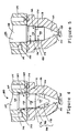
- FIG. 4-8 A partial cross-sectional view of an open nozzle unit injector 100 is shown having a lower plunger 128 reciprocably movable therein and driven by an associated injector drive train (not shown).
- the lower plunger 128 includes a major diameter section 158 that is slidably engaged within a first portion 122 of an axial bore 120 that passes through the barrel 114.
- the lower plunger 128 further includes a minor diameter section 162 that extends within a second portion 124 of the axial bore 120 that is defined within the cup 116.
- a fuel supply passage 146 is also shown within the barrel 114 and includes a supply orifice 152 for allowing fuel flow within the lower end of bore 122 and into the metering chamber of bore 124.
- Figure 4 shows the position of the injector 100 in the metering stage with the lower plunger 128 in a fully retracted position, that is permitting fuel flow from the supply orifice 152 to the metering chamber.
- the direction of fuel flow is indicated by the arrows in Figure 4.
- the minor diameter section 162 and the inner wall 166 are stepped. More specifically, the minor diameter section 162 includes a first substantially constant diameter portion 170 and a second constant diameter portion 172 that are interconnected by an annular step 174.
- the conical plunger tip 129 Extending from the lower end of the second constant diameter portion 172 is the conical plunger tip 129 that is used to force the metered fuel through injection orifices 125 during injection.
- the inner wall 166 is divided into a first portion 176 and a second portion 178 that are connected by an annular step 180 in a similar constant diameter manner as the stepped portions 170 and 172 of the lower plunger 128.
- the present invention allows the diameter of the first portion 176 of the inner wall 166 of cup 116 to be made just slightly larger than the first portion 170 of the lower plunger 128 without adversely affecting metering.
- the second portion 178 of the inner wall 166 is preferably dimensioned just slightly larger than the diameter of the second portion 172 of the lower plunger 128.
- the present Invention design the stepped plunger and cup so that the radial gap x formed between the minor diameter section 162 of the lower plunger 128 and the inner wall 166 of cup 116 can be minimized when the lower plunger 128 is in a fully advanced position as shown in Figure 5. More specifically, the radial gap x is made to be much smaller than the radial gap permitted in the prior art injectors such in Figures 1-3.
- the first portion 170 and the second portion 172 of the minor diameter section 162 of the lower plunger 128 are disposed within the first portion 176 and the second portion 178 of the inner wall 166 of the cup 116, respectively.
- the radial gap x between both the first portions 170 and 176 of the plunger and cup, respectively, and the second portions 172 and 178 of the plunger and cup, respectively, are equal. It is not necessary that they be equal, but it is preferable that they be minimized and equal.
- the radial gap x is made to be much smaller than in the prior art, the stepped plunger and cup injector shown in Figures 4 and 5 does not suffer the deficiencies related to metering sensitively as noted with respect to the prior art and discussed above.
- the axial lengths of the stepped portions are designed such that when the lower plunger 128 is moved upwardly to its fully retracted position, the lower plunger 128 moves an axial distance at least just greater than the length of the lowermost stepped portion shown by portion 172 of the plunger and portion 178 of the inner wall 166 in Figure 4.
- the lowermost plunger portion 172 lies within the next higher inner wall portion 176 that has a sufficiently greater diameter than the lowermost inner wall portion 178 defined by step 180.
- such displacement allows the metering of fuel flow without reduced sensitivity or regard to the specifically minimized radial gap between the plunger and cup when seated as shown in Figure 5.
- annular steps 174 and 180 of the plunger and cup, respectively, define a radial step differential sufficient to guarantee adequate flow even with full carboning.
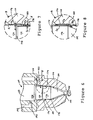
- FIG. 6 a view similar to Figures 4 and 5 is shown except that the lower plunger 128 is in an intermediate position between that shown in Figures 4 and 5.
- This intermediate position corresponds to either a position just subsequent to that in Figure 5 wherein the lower plunger 128 is in the process of being retracted away from the cup 116 which occurs just prior to the start of metering, or to the position just after metering has been completed and injection of fuel within the metering chamber is occurring.
- the annular step 174 on the lower plunger 128 between plunger portions 170 and 172 is offset from the annular step 180 between inner wall surfaces 176 and 178 of the cup 116.
- the plunger surface portion 170 is still in a position partially adjacent the upper inner wall portion 176, and the lowermost plunger portion 172 is still partially adjacent the inner wall portion 178.
- the radial gap or clearance between the minor diameter portions of the plunger and the inner wall of the cup is preferably maintained within the range of between .001 and .004 inches, and the metering clearance is between .006 and .008 inches.
- the clearance can be adjusted according to each specific situation or application, depending on operating conditions and the like.
- the lower plunger minor diameter portions 170 and 172 and cup inner wall surfaces 176 and 178 are illustrated with a carboning layer thereon to the point that the surfaces are considered fully carboned.
- the uppermost minor diameter portion 170 is shown coated with a carbon layer C1 (in cross-section)
- the lowermost minor diameter plunger section 172 is shown coated by a carbon layer C3
- the uppermost cup inner wall portion is coated with a carbon layer C2
- the lowermost cup inner wall portion 178 is coated with a carbon layer C4.
- the total thickness of these carbon layers is advantageously limited by the size of the radial gap x.
- the minor diameter plunger portions 170 and 172 lie partially adjacent the cup inner surface portions 176 and 178, respectively, with the carbon layers C1, C2, and C3, C4, in contact with one another. Then, as the lower plunger 128 is fully retracted, and metering begins, the lowermost minor diameter plunger portion 172 has also been moved to a position above the annular step 180 of the cup inner wall and has assumed a position adjacent to but spaced from the next upper cup inner wall portion 176.
- the carbon layer C3 has assumed a position adjacent the carbon layer C2 which is offset radially away from the carbon layer C3 by an amount defined by the annular step 180.
- This amount of step differential represented by annular step 180 ensures the adequate flow area through the labyrinth flow area even after the plunger and cup surfaces are fully carboned. Thus, an adequate minimal flow area through the labyrinth flow area is guaranteed.
- the stepped plunger and cup design has been found to reduce the effect of carboning on the major diameter section 158 of the lower plunger 128 by reducing the backflow of hot combustion gases that are blown back through the injection orifices 125 from the engine cylinder, by providing barriers along the flow path. These barriers are made by the steps along the radial gap x and by the reduction of the radial gap x itself. The result is that less of the hot combustion gases can migrate upwardly to affect the major diameter section 158 and other elements of the open nozzle injector thereabove.
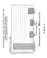
- a standard pressure-time (PT) injector is compared to the stepped plunger and cup (SPC) design of the present invention.
- the graph shows the average injector flow loss through the labyrinth seal area as the injector is subject to carboning.
- the standard PT injector suffers a percentage flow loss as high as 11 percent from cyclic carboning of the injector plunger and cup, while the stepped plunger and cup design, tested at three different radial gaps, showed a maximum of less than 3 percent flow loss caused by the cyclic carboning.
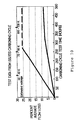
- the graph illustrated in Figure 10 compares the percent average flow loss for a standard PT unit injector, that is, having a plunger and cup design as in Figures 1-3, to a unit injector having a stepped plunger and cup design as illustrated in Figures 4-8 and in accordance with the present invention.
- the percent average flow loss is determined over a test time for a carboning cycle test noted as a 15-second/15-second carboning cycle. This test was conducted by subjecting an engine provided with such injectors for consecutive periods of 15 seconds motoring, then 15 seconds power mode at approximately 60 horsepower. This consecutive cycle was conducted for the time periods noted along the lower horizontal axis of the graph in hours.
- the tests showed percent average flow losses of two to three times more for the standard PT unit injector than the flow losses associated with the stepped plunger and cup design of the present invention.
- the stepped plunger and cup design resulted in percent average flow losses no higher than 8-9 percent.
- the non-stepped standard PT unit injector obtained flow losses as high as 20-30 percent.
- the cyclinder-to-cylinder flow loss variability for the stepped plunger and cup injector was much lower than the variability typically seen on the standard PT unit injectors. This is because the stepped plunger and cup design sets the upper limit for a fully carboned injector which guarantees the adequate fuel metering at a minimum of flow loss.
- a second embodiment of a modified plunger and cup for an open nozzle fuel injector designed in accordance with the present invention is illustrated and described below.
- the plunger and cup are tapered to reduce the diameters thereof in the direction towards the injection orifices 225.
- a plunger 228 includes a major diameter portion 258 slidably engaged within a first bore portion 222 and a minor diameter section 262 extended within a second axial bore portion 224 provided within the cup 216.
- the minor diameter section 262 of the lower plunger 228 is designed to have a decreasing diameter from the point at which the minor diameter section 262 adjoins the major diameter section 258 to the lowermost point of the minor diameter section from which begins the conical tip 229 of the lower plunger 228.
- the inner wall 266 of the cup 216 defined by the second bore portion 224, is similarly tapered so as to decrease the diameter of the bore 224 in the direction from the edge of the cup 216 that abuts the barrel 214 to the end of the cup 216 with the injection orifices 225.
- the tapered inner wall 266 does not affect the normal conical shape of the seat portion 244.
- fuel is metered from supply passage 246 through supply orifice 252 and into the lower end of bore first portion 222 and into the cup bore 224.
- the labyrinth flow area defined between the minor diameter section 262 and the inner wall 266 of the cup 216 permits sufficient fuel flow for fuel metering in accordance with pressure-time principles as enumerated above.
- the trapped volume defined by the radial gap x which is substantially constant along the entire length of the minor diameter section 262 can be minimized.
- the radial gap x is made to be much less than that of conventional straight plunger and cup designs. Then, when the plunger is retracted, the slope of the tapered minor diameter section 262 and inner wall 266 of the cup 216 provide for adequate fuel metering through the labyrinth fuel area.
- the effect of carboning is greatly reduced because even if the carboning upper limit defined by the radial gap x becomes fully carboned, when the lower plunger 228 is fully retracted a sufficient fuel metering gap can be defined by appropriate design of the slope of the tapered surfaces. Additionally, the tapered surfaces and the minimized radial gap x further effectively limit the blow back of combustion gases within the unit injector so as to reduce the effect of carboning on the major diameter section 258 and other injector elements thereabove.
- FIG. 13 and 14 A third embodiment of an open nozzle unit injector 300 designed in accordance with the present invention is illustrated in Figures 13 and 14.
- the injector 300 includes a lower plunger 328 with a major diameter section 358 that is slidably engaged with a first bore portion 322 and a minor diameter section 362 that extends within a second bore portion 324 provided in the cup 316.
- the minor diameter section 362 is of a constant diameter throughout its entire length.
- the inner wall 366 of the cup 316 is provided with stepped portions 376 and 378 with step 380 therebetween. These stepped portions, 376 and 378, are similarly designed as the first and second stepped portions 176 and 178 of the embodiment shown in Figures 4-8.
- this embodiment losses some of the effect of the stepped plunger and cup design of Figures 4 and 5 in that only the lowermost step provided by portion 378 of the inner wall 366 is designed to minimize the radial gap x thereat, while a second radial gap y is defined between the minor diameter section 362 and the first portion 376 of the inner wall 366 of cup 316.
- the radial gap y is greater than the radial gap x.
- the upper limit of carboning is set between plunger portion 362 and cup inner wall portion 378.
- such a design allows an injector to be manufactured with only the cup 216 modified.
- This embodiment permits the manufacture of an improved open nozzle injector with a substantially reduced cost since no additional machining is necessary for the lower plunger 328, but which effectively at least reduces a substantial portion of the trapped volume.
- this embodiment permits the retrofitting of open nozzle injectors already in existence with a stepped cup with the non-stepped plunger assembly of the retrofitted injector.
- FIG. 15 and 16 A further modification that may be applied to any of the above described embodiments but specifically shown as a modification of the Figures 13 and 14 embodiment is illustrated in Figures 15 and 16.
- Such a further modification is provided by an insert 400 that is separately manufactured and provided within an enlarged bore 402 of the cup 404.
- the inner bore 406 of the insert 400 is specifically shown with a stepped design, but it is understood that the insert could be equally used to provide a tapered design as described above.
- the insert can be used with or without a stepped plunger design as also described above.
- the insert can be used for retrofitting non-stepped or non-tapered prior art injector cups that must only then be bored out for retrofitting and use in an open nozzle injector in a way to take advantage of the above described benefits.
Landscapes
- Engineering & Computer Science (AREA)
- Chemical & Material Sciences (AREA)
- Combustion & Propulsion (AREA)
- Mechanical Engineering (AREA)
- General Engineering & Computer Science (AREA)
- Fuel-Injection Apparatus (AREA)
Applications Claiming Priority (2)
| Application Number | Priority Date | Filing Date | Title |
|---|---|---|---|
| US514431 | 1983-07-18 | ||
| US07/514,431 US5037031A (en) | 1990-04-25 | 1990-04-25 | Reduced trapped volume |
Publications (2)
| Publication Number | Publication Date |
|---|---|
| EP0454439A1 true EP0454439A1 (fr) | 1991-10-30 |
| EP0454439B1 EP0454439B1 (fr) | 1995-03-08 |
Family
ID=24047099
Family Applications (1)
| Application Number | Title | Priority Date | Filing Date |
|---|---|---|---|
| EP91303684A Expired - Lifetime EP0454439B1 (fr) | 1990-04-25 | 1991-04-24 | Pompe-injecteur de combustible |
Country Status (4)
| Country | Link |
|---|---|
| US (1) | US5037031A (fr) |
| EP (1) | EP0454439B1 (fr) |
| JP (1) | JPH0784856B2 (fr) |
| DE (1) | DE69107887T2 (fr) |
Cited By (1)
| Publication number | Priority date | Publication date | Assignee | Title |
|---|---|---|---|---|
| WO2002048539A1 (fr) * | 2000-12-11 | 2002-06-20 | Robert Bosch Gmbh | Soupape d'injection de carburant |
Families Citing this family (16)
| Publication number | Priority date | Publication date | Assignee | Title |
|---|---|---|---|---|
| US5449121A (en) * | 1993-02-26 | 1995-09-12 | Caterpillar Inc. | Thin-walled valve-closed-orifice spray tip for fuel injection nozzle |
| US5445323A (en) * | 1993-08-23 | 1995-08-29 | Cummins Engine Company, Inc. | High pressure fuel injector including a trapped volume spill port |
| US6257499B1 (en) | 1994-06-06 | 2001-07-10 | Oded E. Sturman | High speed fuel injector |
| US6161770A (en) | 1994-06-06 | 2000-12-19 | Sturman; Oded E. | Hydraulically driven springless fuel injector |
| US6148778A (en) | 1995-05-17 | 2000-11-21 | Sturman Industries, Inc. | Air-fuel module adapted for an internal combustion engine |
| DE19528807C2 (de) * | 1995-08-05 | 2000-06-08 | Dahlmann Gerd Uwe | Kraftstoff-Einspritzventil mit integrierter Pumpe |
| US5894991A (en) * | 1997-08-22 | 1999-04-20 | Cummins Engine Company, Inc. | Unit injector with hard stop timing plunger |
| JP3567732B2 (ja) * | 1998-04-28 | 2004-09-22 | 株式会社日立製作所 | 燃料噴射弁 |
| US6085991A (en) | 1998-05-14 | 2000-07-11 | Sturman; Oded E. | Intensified fuel injector having a lateral drain passage |
| US6491237B1 (en) * | 2000-06-12 | 2002-12-10 | Hatch & Kirk, Inc. | Fuel injector nozzle |
| US6918549B2 (en) * | 2001-12-21 | 2005-07-19 | Caterpillar Inc | Fuel injector tip for control of fuel delivery |
| JP2004028051A (ja) * | 2002-06-28 | 2004-01-29 | Denso Corp | 燃料噴射ノズルおよびその製造方法 |
| US7201135B2 (en) * | 2005-03-09 | 2007-04-10 | Caterpillar Inc | Internal combustion engine |
| US7597084B2 (en) * | 2005-03-09 | 2009-10-06 | Caterpillar Inc. | Internal combustion engine and operating method therefor |
| DE102015225733A1 (de) * | 2015-12-17 | 2017-06-22 | Robert Bosch Gmbh | Kraftstoffeinspritzdüse |
| DE102016215637A1 (de) * | 2016-08-19 | 2018-02-22 | Robert Bosch Gmbh | Kraftstoffeinspritzdüse |
Citations (2)
| Publication number | Priority date | Publication date | Assignee | Title |
|---|---|---|---|---|
| US3351288A (en) * | 1964-03-25 | 1967-11-07 | Cummins Engine Co Inc | Fuel injector |
| US3409225A (en) * | 1966-06-14 | 1968-11-05 | Int Harvester Co | Mechanical injector having needleseating spring |
Family Cites Families (5)
| Publication number | Priority date | Publication date | Assignee | Title |
|---|---|---|---|---|
| US3836080A (en) * | 1973-09-10 | 1974-09-17 | Ambac Ind | Fuel injection nozzle |
| DE2709917A1 (de) * | 1977-03-08 | 1978-09-14 | Bosch Gmbh Robert | Kraftstoffeinspritzduese |
| US4280659A (en) * | 1979-07-23 | 1981-07-28 | Cummins Engine Company, Inc. | Fuel injector |
| DE3237882A1 (de) * | 1982-10-13 | 1984-04-19 | Robert Bosch Gmbh, 7000 Stuttgart | Kraftstoff-einspritzduese fuer brennkraftmaschinen |
| US4601086A (en) * | 1984-10-15 | 1986-07-22 | Cummins Atlantic, Inc. | Method of manufacturing top stop-type fuel injector |
-
1990
- 1990-04-25 US US07/514,431 patent/US5037031A/en not_active Expired - Lifetime
-
1991
- 1991-04-24 EP EP91303684A patent/EP0454439B1/fr not_active Expired - Lifetime
- 1991-04-24 DE DE69107887T patent/DE69107887T2/de not_active Expired - Lifetime
- 1991-04-25 JP JP3122746A patent/JPH0784856B2/ja not_active Expired - Lifetime
Patent Citations (2)
| Publication number | Priority date | Publication date | Assignee | Title |
|---|---|---|---|---|
| US3351288A (en) * | 1964-03-25 | 1967-11-07 | Cummins Engine Co Inc | Fuel injector |
| US3409225A (en) * | 1966-06-14 | 1968-11-05 | Int Harvester Co | Mechanical injector having needleseating spring |
Cited By (1)
| Publication number | Priority date | Publication date | Assignee | Title |
|---|---|---|---|---|
| WO2002048539A1 (fr) * | 2000-12-11 | 2002-06-20 | Robert Bosch Gmbh | Soupape d'injection de carburant |
Also Published As
| Publication number | Publication date |
|---|---|
| US5037031A (en) | 1991-08-06 |
| JPH04228873A (ja) | 1992-08-18 |
| EP0454439B1 (fr) | 1995-03-08 |
| DE69107887T2 (de) | 1995-10-26 |
| DE69107887D1 (de) | 1995-04-13 |
| JPH0784856B2 (ja) | 1995-09-13 |
Similar Documents
| Publication | Publication Date | Title |
|---|---|---|
| US5037031A (en) | Reduced trapped volume | |
| US4715541A (en) | Fuel injection nozzle for combustion engines | |
| USRE34999E (en) | Hole type fuel injector and injection method | |
| EP0449763B1 (fr) | Injecteur de carburant | |
| US4986472A (en) | High pressure unit fuel injector with timing chamber pressure control | |
| US4280659A (en) | Fuel injector | |
| CN1188591C (zh) | 喷油嘴 | |
| AU2018213906B2 (en) | Internal combustion engine comprising a fuel injection nozzle with an additional supply of a combustion-promoting medium into the combustion chamber | |
| WO2011033036A1 (fr) | Soupape d'injection de carburant pour un moteur à combustion interne | |
| US5445323A (en) | High pressure fuel injector including a trapped volume spill port | |
| US5076236A (en) | Fuel cutoff for better transient control | |
| US5042721A (en) | Reduced gas flow open nozzle unit injector | |
| US5040727A (en) | Unit fuel injector with plunger minor diameter floating sleeve | |
| CN106014739A (zh) | 一种喷油嘴 | |
| US5894991A (en) | Unit injector with hard stop timing plunger | |
| US5076240A (en) | Articulated open nozzle high pressure unit fuel injector | |
| US4601086A (en) | Method of manufacturing top stop-type fuel injector | |
| DE102015016918A1 (de) | Brennraumstruktur für einen Motor und Verbrennungsmotor | |
| EP0726385A1 (fr) | Soupape d'admission pour chambre de combustion de moteur à combustion interne | |
| CN1853042A (zh) | 用于内燃机的燃油喷射阀 | |
| WO2012076753A1 (fr) | Appareil d'injection de carburant, moteur à piston et procédé de faire fonctionner un moteur à piston | |
| USRE32703E (en) | Throttling-pintle nozzle for fuel injection in an internal-combustion engine | |
| US6945233B2 (en) | System and method of optimizing fuel injection timing in a locomotive engine | |
| Sczomak | The poppet covered orifice fuel injection nozzle | |
| CA1273252A (fr) | Injecteur a butee double, pour carburant, et sa fabrication |
Legal Events
| Date | Code | Title | Description |
|---|---|---|---|
| PUAI | Public reference made under article 153(3) epc to a published international application that has entered the european phase |
Free format text: ORIGINAL CODE: 0009012 |
|
| AK | Designated contracting states |
Kind code of ref document: A1 Designated state(s): DE GB |
|
| 17P | Request for examination filed |
Effective date: 19920410 |
|
| 17Q | First examination report despatched |
Effective date: 19920610 |
|
| GRAA | (expected) grant |
Free format text: ORIGINAL CODE: 0009210 |
|
| AK | Designated contracting states |
Kind code of ref document: B1 Designated state(s): DE GB |
|
| REF | Corresponds to: |
Ref document number: 69107887 Country of ref document: DE Date of ref document: 19950413 |
|
| PLBE | No opposition filed within time limit |
Free format text: ORIGINAL CODE: 0009261 |
|
| STAA | Information on the status of an ep patent application or granted ep patent |
Free format text: STATUS: NO OPPOSITION FILED WITHIN TIME LIMIT |
|
| 26N | No opposition filed | ||
| REG | Reference to a national code |
Ref country code: GB Ref legal event code: IF02 |
|
| PGFP | Annual fee paid to national office [announced via postgrant information from national office to epo] |
Ref country code: DE Payment date: 20100428 Year of fee payment: 20 |
|
| PGFP | Annual fee paid to national office [announced via postgrant information from national office to epo] |
Ref country code: GB Payment date: 20100426 Year of fee payment: 20 |
|
| REG | Reference to a national code |
Ref country code: DE Ref legal event code: R071 Ref document number: 69107887 Country of ref document: DE |
|
| REG | Reference to a national code |
Ref country code: GB Ref legal event code: PE20 Expiry date: 20110423 |
|
| PG25 | Lapsed in a contracting state [announced via postgrant information from national office to epo] |
Ref country code: GB Free format text: LAPSE BECAUSE OF EXPIRATION OF PROTECTION Effective date: 20110423 |
|
| PG25 | Lapsed in a contracting state [announced via postgrant information from national office to epo] |
Ref country code: DE Free format text: LAPSE BECAUSE OF EXPIRATION OF PROTECTION Effective date: 20110424 |