EP0453864B1 - Kassette für einen photographischen Film - Google Patents
Kassette für einen photographischen Film Download PDFInfo
- Publication number
- EP0453864B1 EP0453864B1 EP19910105587 EP91105587A EP0453864B1 EP 0453864 B1 EP0453864 B1 EP 0453864B1 EP 19910105587 EP19910105587 EP 19910105587 EP 91105587 A EP91105587 A EP 91105587A EP 0453864 B1 EP0453864 B1 EP 0453864B1
- Authority
- EP
- European Patent Office
- Prior art keywords
- film
- photographic film
- cassette according
- cassette
- film cassette
- Prior art date
- Legal status (The legal status is an assumption and is not a legal conclusion. Google has not performed a legal analysis and makes no representation as to the accuracy of the status listed.)
- Expired - Lifetime
Links
- 239000004744 fabric Substances 0.000 claims description 56
- 239000000853 adhesive Substances 0.000 claims description 13
- 210000000078 claw Anatomy 0.000 claims description 8
- 238000000926 separation method Methods 0.000 claims description 7
- 239000007787 solid Substances 0.000 claims description 3
- 230000000903 blocking effect Effects 0.000 claims description 2
- 238000003825 pressing Methods 0.000 claims description 2
- 239000010408 film Substances 0.000 description 101
- 239000003795 chemical substances by application Substances 0.000 description 19
- 239000004831 Hot glue Substances 0.000 description 16
- 210000002105 tongue Anatomy 0.000 description 6
- 230000001070 adhesive effect Effects 0.000 description 5
- 239000000463 material Substances 0.000 description 5
- 239000002390 adhesive tape Substances 0.000 description 4
- 238000010276 construction Methods 0.000 description 4
- 238000002474 experimental method Methods 0.000 description 4
- 229920000297 Rayon Polymers 0.000 description 3
- 230000000052 comparative effect Effects 0.000 description 3
- 239000002964 rayon Substances 0.000 description 3
- 239000004820 Pressure-sensitive adhesive Substances 0.000 description 2
- NIXOWILDQLNWCW-UHFFFAOYSA-N acrylic acid group Chemical group C(C=C)(=O)O NIXOWILDQLNWCW-UHFFFAOYSA-N 0.000 description 2
- 230000004927 fusion Effects 0.000 description 2
- -1 polypropylene Polymers 0.000 description 2
- 238000007639 printing Methods 0.000 description 2
- QTBSBXVTEAMEQO-UHFFFAOYSA-M Acetate Chemical compound CC([O-])=O QTBSBXVTEAMEQO-UHFFFAOYSA-M 0.000 description 1
- 229920002972 Acrylic fiber Polymers 0.000 description 1
- 229920000742 Cotton Polymers 0.000 description 1
- 239000004677 Nylon Substances 0.000 description 1
- 239000004698 Polyethylene Substances 0.000 description 1
- 239000004743 Polypropylene Substances 0.000 description 1
- 239000004793 Polystyrene Substances 0.000 description 1
- BZHJMEDXRYGGRV-UHFFFAOYSA-N Vinyl chloride Chemical compound ClC=C BZHJMEDXRYGGRV-UHFFFAOYSA-N 0.000 description 1
- 229920002978 Vinylon Polymers 0.000 description 1
- 239000006229 carbon black Substances 0.000 description 1
- 229920001577 copolymer Polymers 0.000 description 1
- 230000003247 decreasing effect Effects 0.000 description 1
- 238000010586 diagram Methods 0.000 description 1
- 230000000694 effects Effects 0.000 description 1
- 239000000835 fiber Substances 0.000 description 1
- 238000007667 floating Methods 0.000 description 1
- 229920005669 high impact polystyrene Polymers 0.000 description 1
- 239000004797 high-impact polystyrene Substances 0.000 description 1
- 239000002649 leather substitute Substances 0.000 description 1
- 238000004519 manufacturing process Methods 0.000 description 1
- 238000005259 measurement Methods 0.000 description 1
- 238000002844 melting Methods 0.000 description 1
- 230000008018 melting Effects 0.000 description 1
- 238000000034 method Methods 0.000 description 1
- 239000000203 mixture Substances 0.000 description 1
- 239000004745 nonwoven fabric Substances 0.000 description 1
- 229920001778 nylon Polymers 0.000 description 1
- 239000004417 polycarbonate Substances 0.000 description 1
- 229920000515 polycarbonate Polymers 0.000 description 1
- 229920000728 polyester Polymers 0.000 description 1
- 229920000573 polyethylene Polymers 0.000 description 1
- 229920000642 polymer Polymers 0.000 description 1
- 229920001155 polypropylene Polymers 0.000 description 1
- 229920002223 polystyrene Polymers 0.000 description 1
- 229920005990 polystyrene resin Polymers 0.000 description 1
- 230000007420 reactivation Effects 0.000 description 1
- 229920002994 synthetic fiber Polymers 0.000 description 1
- 239000012209 synthetic fiber Substances 0.000 description 1
- 238000002604 ultrasonography Methods 0.000 description 1
- 238000004804 winding Methods 0.000 description 1
Images


Classifications
-
- G—PHYSICS
- G03—PHOTOGRAPHY; CINEMATOGRAPHY; ANALOGOUS TECHNIQUES USING WAVES OTHER THAN OPTICAL WAVES; ELECTROGRAPHY; HOLOGRAPHY
- G03B—APPARATUS OR ARRANGEMENTS FOR TAKING PHOTOGRAPHS OR FOR PROJECTING OR VIEWING THEM; APPARATUS OR ARRANGEMENTS EMPLOYING ANALOGOUS TECHNIQUES USING WAVES OTHER THAN OPTICAL WAVES; ACCESSORIES THEREFOR
- G03B17/00—Details of cameras or camera bodies; Accessories therefor
- G03B17/28—Locating light-sensitive material within camera
- G03B17/30—Locating spools or other rotatable holders of coiled film
-
- G—PHYSICS
- G03—PHOTOGRAPHY; CINEMATOGRAPHY; ANALOGOUS TECHNIQUES USING WAVES OTHER THAN OPTICAL WAVES; ELECTROGRAPHY; HOLOGRAPHY
- G03B—APPARATUS OR ARRANGEMENTS FOR TAKING PHOTOGRAPHS OR FOR PROJECTING OR VIEWING THEM; APPARATUS OR ARRANGEMENTS EMPLOYING ANALOGOUS TECHNIQUES USING WAVES OTHER THAN OPTICAL WAVES; ACCESSORIES THEREFOR
- G03B2217/00—Details of cameras or camera bodies; Accessories therefor
- G03B2217/26—Holders for containing light-sensitive material and adapted to be inserted within the camera
- G03B2217/265—Details of light-proofing
Definitions
- the present invention relates to a photographic film cassette, having a spool with photographic film wound thereon and a cassette shell for containing the film in a light tight manner and for rotatably supporting said spool, said cassette shell having a film passageway adapted for directing the film to the outside through a film passage mouth, said cassette further comprising two light trapping members provided on first and second inside surfaces of said film passageway, respectively, for trapping light, and an inner recess portion extending in parallel to the longitudinal axis of said spool and being formed within at least one of said first and second inside surfaces.
- a photographic film cassette of this type is known from US-A-4 848 693 wherein light trapping fabrics such as velvet or plush material is attached to the film passage mouth. It is generally known to attach the light trapping fabrics by means of adhesive agent or double-coated adhesive tape.
- the light trapping fabrics may consist of known black-dyed velvet constituted by ground fabric and pile threads densely planted thereon. Dense provision of the pile threads fills the film passage mouth to shield the inside of the cassette shell from light coming to the film passage mouth.
- leading end of the negative film forced to advance may peel off the light trapping fabrics if the light trapping fabrics are not firmly attached to the film passageway.
- Another light type film cassette is known from US-4 634 071 having a so-called "floating light seal" which can shift up and downwards to automatically adjust the number of windings of a film spool. Edges of plush-like material preventing ambient light from entering through a film passage mouth are movably received within recesses at the film passage mouth.
- the present invention intends to provide a photographic film cassette as defined by the preamble portion of claim 1 which has failure safe light trapping properties at the film passage mouth.
- a photographic film cassette of the type mentioned above wherein an inner edge of one of said light trapping members which is provided on one of said first and second inside surfaces is attached to the inside of the corresponding inner recess portion which is provided on said one of said first and second inside surfaces in order to prevent blocking of the leading end of the film at the inner edge during film advancement.
- means are provided for enclosing said inner edge within the respective recess portions thereby preventing engagement of the leading end of the film with an edge of a light trapping member.
- a roughened surface structure is formed in the respective recess portions for keeping firm attachment of the light trapping members to the film passage mouth.
- the photographic film cassette comprises light shielding means for shielding a lateral edge portion of the film from light, formed in contacting surfaces of first and second shell halves of the film cassette thereby fogging on lateral edge portions of the negative film can be sufficiently prevented.
- the first and second shell halves include respectively first and second edges formed thereon for being joined together to constitute a juncture.
- the light shielding means include a central projection formed on the first edge while the other edge is formed by an outside projection and an inside projection, both defining a group therebetween for engaging said central projection.
- the light shielding means is a deformed portion formed along the juncture. Fogging is sufficiently prevented on the lateral edge portions of the film.
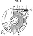
- a film cassette 2 is constituted by a cassette shell molded from polystyrene resin of light-shielding property and photographic film e.g. negative film 4 wound on a spool 5 contained therein, which cassette shell consists of an upper shell half 13 and a lower shell half 14 each substantially in the semicylindrical shape.
- Flanges 5a are formed on positions near both ends of the spool 5 for keep flat both lateral sides of the roll film 4 and for preventing light from entering through a sliding space between the spool 5 and the shell halves 13 and 14.
- Circumferential lips 5b are integratedly formed on the circular edges of the flanges 5a in order to prevent the negative film 4 from loosening by receiving both lateral edges of the outermost turn of the roll film 4. This construction causes the clockwise rotation of the spool 5 to rotate a leading end 4a of the negative film 4 in the unwinding direction.
- a pair of guide ridges 6b are formed on the lower shell half 14, and are provided with separation claws 7 on their inner end.
- the lateral sides of the separation claws 7 release the lips 5b from the roll film 4 by pressing part of the lips 5b outwardly.
- the tips of the separation claws 7 separate the leading end 4a from the outermost turn of the roll film 4 when in contact with the leading end 4a.
- the guide ridges 6b direct the leading end 4a to a film passageway 9 in cooperation with guide ridges 6a formed on the upper shell half 13 later to be described.
- Upper and lower inside surfaces 9a and 9b of the film passageway 9 are provided with a pair of light trapping fabrics 10 and 11 adhered thereto, which fabrics consist of velvet fabric woven from rayon.
- the leading end 4a of the negative film 4 is fed between the fabrics 10 and 11 and advanced to the outside of the cassette shell through a film passage mouth 12.
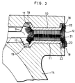
- Tongues 15 and 16 are formed on edges of the upper and lower shell halves 13 and 14 along the lengthwise direction of the cassette 2. The fabrics 10 and 11 having been adhered, the upper and lower shell halves 13 and 14 are joined together to cause the tongues 15 and 16 to form the film passageway 9.
- Inner recesses 17 are formed each on the upper and lower inside surfaces 9a and 9b extending in a direction vertical to the spool 5.
- Outer recesses 18 are formed in the film passage mouth 12 on the upper and lower inside surfaces 9a and 9b in parallel with the inner recesses 17.
- An inclined plane is formed in the inner recesses 17 on the side near the film passage mouth 12 to enlarge the interval between the upper and lower inside surfaces 9a and 9b gradually in the inward direction in parallel with the lengthwise direction of the cassette 2. This inclination prevents the inner recesses 17 from stopping the leading end 4a during advance.
- the inner recesses 17 in the present embodiment may be replaced with inclined recesses.
- Acrylic hot-melt adhesive agent 19 is applied to the inner recesses 17 in a solid condition in the shape of a stick.
- the fabrics 10 and 11 consist of ground fabric 20 and pile threads 21.
- Hot-melt adhesive agent 22 is applied to a plane in the outer recesses 18 to attach the outer edge of the ground fabric 20 thereto.
- the inner edges of the fabrics 10 and 11 are inserted in the inner recesses 17, while their outer edges are inserted in the outer recesses 18.
- the inner and outer edges are heated by a heat sealer to 200 o C for 5 seconds.
- the hot-melt adhesive agent 19 is melted in the inner recesses 17 to enclose the inner edges of the ground fabric 20, while the hot-melt adhesive agent 22 is melted in the outer recesses 18 to attach the outer edges of the ground fabric 20 to the lower shell half 14.
- the hot-melt adhesive agent 19 and 20 is melted by the heat sealer in the present embodiment, there are methods of adhesion in fusion and reactivation by use of ultrasound or high frequency energy.
- a solid hot-melt adhesive agent is melted in the inner recesses 17 in this embodiment, melted hot-melt adhesive agent may also be poured therein.
- the inner edges of the fabrics 10 and 11 may also be enclosed in fusion of a projecting portions formed in advance on the shell halves 13 and 14.
- the middle of the fabrics 10 and 11 has no need of adhesion. However, it is possible to adhere this middle when it is necessary to precisely adjust the degree of contact or lapping between pile threads 21 of the upper and lower fabrics 10 and 11.
- hot-melt adhesive agent 23 is applied to the lower inside surface 9b in a dotted disposition, because melting must be carried out without such pressure applied to the whole of the middle of the fabrics 10 and 11 as is large enough to bend the pile threads 21.
- the hot-melt adhesive agent 23 is preferably prevented from being dotted to be in lines parallel to the advancing direction of the negative film 4. The positions where the pile threads 21 are pressed thus can be sparse, thereby reliably preventing light from entering the cassette 2 through the film passageway 9.
- rayon is used for manufacturing the fabrics 10 and 11 in the present embodiment
- other materials including: synthetic fibers such as nylon, acrylic fibers, polyester, vinylon, vinyl chloride, vinylidene copolymer, polypropylene and polyethylene polycarbonate; and natural or regenerated fibers such as cupro-ammonium rayon, acetate, cotton and silk.
- synthetic fibers such as nylon, acrylic fibers, polyester, vinylon, vinyl chloride, vinylidene copolymer, polypropylene and polyethylene polycarbonate
- natural or regenerated fibers such as cupro-ammonium rayon, acetate, cotton and silk.
- the knitted fabrics 10 and 11 having pile threads are used for light trapping members, they also may be film-type light trapping material, nonwoven fabric, fabric or film with pile threads planted thereon, synthetic leather, or sponge of elastic property.
- the operation of the above film cassette 2 according to the present invention is now described.
- the film passageway 9 is shielded from light by the fabrics 10 and 11 so as to keep light-tight the inside of the cassette 2 containing the whole of the roll film 4 up to the leading end 4a.
- a drive mechanism incorporated in the camera rotates the spool 5 in the unwinding direction. This rotation causes the leading end 4a to rotate in the same direction until contact with the separation claws 7, which separates the leading end 4a from the outermost turn of the roll film 4.
- the leading end 4a thus separated is guided by the guide ridges 6a and 6b and fed to the film passageway 9.
- the inner recesses 17 in the film passageway 9 has an inclination decreasing the interval of the film passageway 9 in the direction to the outside of the cassette 2, so that the tip 4a of the negative film 4 is never stopped by the inner recesses 17.
- the leading end 4a is guided by the inclined portions formed in inner positions on the fabrics 10 and 11 to be directed to the position of contact between the upper and lower of the pile threads 21.
- the fabrics 10 and 11 receive a force in the direction of peeling the fabrics 10 and 11. However, they are never peeled off because their inner edges are adhered in a condition enclosed in the hot-melt adhesive agent 19.
- the leading end 4a is then advanced to the outside of the cassette 2 through the film passageway 9 between the fabrics 10 and 11, during which the inside of the cassette 2 is kept light-tight because the pile threads 21 remain in contact with both surfaces of the negative film 4.
- Fig. 5 illustrating another preferred embodiment of the inventive film cassette
- rough or uneven surfaces are formed by providing tiny grooves 33 on a bottom surface 17a and an inclined surface 17b in the inner recesses 17, and a bottom surface 18a and an inclined surface 18b forming the outer recesses 18.
- the tiny grooves 33 are formed integratedly with the upper and lower shell halves 13 and 14 when they are molded.
- Each of the tiny grooves 33 has a very small size, such that two adjacent tiny grooves form a ridge having a tip which has an interval of 0.1 mm with an adjacent similar tip.
- the inside of the recesses 17 and 18 are formed with tiny grooves 33, they may be formed with tiny recesses in a densely dotted disposition. Such construction makes it possible to enlarge the area to be attached to the fabrics 10 and 11.
- Acrylic hot-melt adhesive agent is in advance applied to the bottom surface 17a, the inclined surface 17b, the bottom surface 18a and the inclined surface 18b.
- the shell halves 13 and 14 are formed by molds with tiny ridges corresponding to the tiny grooves.
- molds with tiny projections may be used so that corresponding tiny recesses are formed on the shell halves 13 and 14.
- tiny recesses instead may be formed by filing the molded shell halves. Rough surfaces with such tiny grooves or tiny recesses may be formed not only in the inner and outer recesses 17 and 18 but on the whole surface of the film passageway 9 in contact with the fabrics 10 and 11.
- the hot-melt adhesive agent 34 is in advance provided in the shell halves 13 and 14 and melted to adhere the fabrics 10 and 11.
- melted hot-melt adhesive agent may be poured when the fabrics 10 and 11 is adhered.
- hot-melt adhesive agent may be applied to both inner and outer edges of the fabrics 10 and 11 to be melted.
- the hot-melt adhesive agent may be replaced with pressure-sensitive adhesive agent, adhesive tape with pressure-sensitive adhesive agent applied to a base material, or hardening agent to be hardened naturally or by heat after adhesion.
- the adhesive force was 1240 g / 10 mm in Sample 1, 950 g / 10 mm in Sample 2, and 320 g / 10 mm in Comparative Example. Having been kept for 48 hours under the condition of 60 o C in temperature and 80 % in relative humidity, the adhesive force was 1250 g / 10 mm in Sample 1, 850 g / 10 mm in Sample 2, and 150 g / 10 mm in Comparative Example.
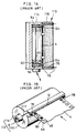
- a film cassette 40 illustrated in Fig. 6 serves to prevent fogging from developing on the lateral edge portions of the negative film 4. Elements similar to those in the above embodiments are designated by the same reference numerals.
- the cassette 40 consists of an upper and lower shell halves 41 and 42 and the spool 5 with the negative film 4 wound thereon.
- a pair of annular ridges 47 are formed on an interior surface 46 of the upper shell half 41 for reducing the area of contact between the outermost turn of the roll film 4 and the interior surface 46, thereby making it easy to advance the leading end 4a as well as preventing the roll film 4 from loosening.
- Both shell halves 41 and 42 are made from polymer of mixture of high-impact polystyrene with general polystyrene in the ratio of 50 to 50 in weight with carbon black added thereto by 0.5 % in weight.
- the upper shell half 41 is provided with a stepped edge 41a to be joined with the lower shell half 42.
- the stepped edge 41a is constituted by a central projection 51 of a height H 1 .
- Both end faces of the upper shell half 41 are provided with bearing recesses 53 for rotatably supporting the spool 5 in cooperation with the counterpart of the lower shell half 42.
- the spool 5 is provided with a pair of ordinary flanges 54.
- Lateral edge portions 4b of the negative film 4 carry DX code 60 for representing the type of film to be used for printing.
- the fabrics 10 and 11 each disposed on the tongues 15 and 16 have a width W 1 of 5 mm.
- the separation claws 7 formed on the tongue 16 serve just to separate the leading end 4a, from which claws annular ridges (not shown) on the interior surface of the lower shell half 42 extend to be connected to the ridges 47.
- the lower shell half 42 is provided with bearing recesses 59 on both end faces.
- a stepped edge 42a of the lower shell half 42 is retracted on the center forming a groove 61.
- a contact projection 62 defines the groove 61 and has a height H 2
- an outside projection 63 defines the same on the outside and has the height of H 1 as illustrated in Fig. 7.
- Both of the shell halves 41 and 42 have a thickness D 1 of 0.8 mm.
- Junction of the shell halves 41 and 42 causes the tongues 15 and 16 to form the film passageway 9 and the film passage mouth 12.
- a spacing or groove 66 is defined between the shell halves 41 and 42 and has a width ⁇ H which is equal to H 2 minus H 1 , and substantially determined to be 0.15 mm.
- the spacing 66 surrounds the exterior periphery of the cassette 40 as illustrated in Fig. 8. Because the interior surface of the cassette shell has no such spacing, external light is prevented from entering the cassette 40 through the stepped edges 41a and 42a, thereby preventing fogging from being generated on the lateral edge portions 4b.
- the diameter D 2 of the cassette 40 is determined to be 23 mm. Its length W 0 in the direction parallel to the spool 5 is determined to be 41 mm.
- the cassette 40 When the exposure of the film 4 is completed, the cassette 40 is unloaded from the camera.
- the stepped edges 41a and 42a reliably shield the negative film 4 in the film passageway 9. Accordingly the lateral edge portions 4b of the negative film 4 involve no fogging so that the DX code 60 can be read out at the printing time.
- Experiments were made regarding the capability in shielding light.
- Ten film cassettes the same as the above cassette 40 and ten conventional cassettes are subjected to light of 100,000 lux for 3 minutes, from which cassettes negative film was drawn out and developed. In five of the ten conventional cassette, there was fogging on the lateral edge portions of the roll film on the 3 or 5 outermost turns, while no fogging was recognized on the negative film 4 of the cassettes the same as the cassette 40.
- a juncture 73 of upper and lower film cassettes 71 and 72 includes a deformed or crooked portion 76 in a position beside light trapping fabric 74, where the juncture 73 is not straight.
- the film passage mouth 12 of the cassette 70 involves a spacing 78 on the lateral sides as illustrated in Fig. 10. External light 79 entering the cassette 70 through the spacing 78, however, is reflected and scattered by the crooked portion 76 and absorbed by the fabric 74.
- the spacing 78 is the same as that included in a conventional cassette, fogging is reliably prevented on the lateral edge portions 4b of the negative film 4.
- a similar effect is brought by a crooked portion 81 in the arcuate shape beside the fabric 74 as illustrated in Fig. 11.
- the fabric 74 may be replaced with a sponge-type light trapping member disposed in the film passageway 9.
- crooked portions 92 and 93 may be arranged beside the flanges 54 of the spool 5 as illustrated in Fig. 12.
- spacings 94 and 96 defined between the spool 5 and the bearing recesses 53 and 59, external light enters the cassette shell, but is reflected/scattered by the crooked portions 92 and 93 and absorbed by the flanges 54. It is accordingly possible to completely shield the cassette from light. It is noted that the spacings 94 and 96 are illustrated in exaggeration particularly in Fig. 12 and actually have a tiny size.
- crooked edges 15a and 16a may be formed on the tongues 15 and 16 to become parallel with a plane defined by the film passage mouth 12 as illustrated in Fig. 13A.
- a spacing 103 is defined along the juncture inside the film passage mouth 12 as illustrated in Fig. 13B.
- the spacing 103 is crooked at an inner corner 104. Entering the spacing 103, external light 106 is reflected/scattered by the inner corner 104 and absorbed by the fabric 74. Light shielding capacity is highly improved by this construction beside the lateral edge portions of the negative film.
- any of the above-described embodiments involves a self-advancing film cassette with even the leading end 4a of the roll film 4 contained in the cassette shell, in which the rotation of the spool 5 causes the leading end 4a to advance to the outside of the cassette shell.
- these embodiments can be applied to a general type of film cassette with the leading end 4a of the negative film 4 protruded to the outside of the cassette shell.
Landscapes
- Physics & Mathematics (AREA)
- General Physics & Mathematics (AREA)
- Details Of Cameras Including Film Mechanisms (AREA)
- Photographic Developing Apparatuses (AREA)
- Packaging Of Annular Or Rod-Shaped Articles, Wearing Apparel, Cassettes, Or The Like (AREA)
Claims (25)
- Kassette (2) für photographische Filme mit einer Spule (5), um die ein photographischer Film (4) gewickelt ist, und einer Kassettenschale (13,14) zur lichtdichten Aufnahme des Filmes (4) und zur drehbaren Abstützung der Spule (5), wobei die Kassettenschale (13,14) eine Filmdurchgangsöffnung (9) aufweist, die zur Führung des Filmes (4) nach außen durch eine Filmdurchgangsmündung (12) dient, wobei die Kassette (13,14) weiterhin aufweist:zwei Lichtschutzelemente (10,11), die jeweils an ersten und zweiten Innenflächen (9a,9b) der Filmdurchgangsöffnung (9) zum Abhalten von Licht vorgesehen sind; undeinen inneren Vertiefungsabschnitt (17), der sich parallel zur Längsachse der Spule (5) erstreckt und zumindest in einer der ersten und zweiten Innenflächen (9a,9b) ausgebildet ist,dadurch gekennzeichnet, daß
ein Innenrand eines der Lichtschutzelemente (10,11), das an einer der ersten und zweiten Innenflächen (9a,9b) vorgesehen ist, an der Innenseite des zugehörigen inneren Vertiefungsabschnitts (17) angebracht ist, der an einem der ersten und zweiten Innenflächen (9a,9b) vorgesehen ist, um ein Blockieren des Führungsendes (4a) des Filmes (4) an dem Innenrand während des Filmtransportes zu verhindern, und daß Vorrichtungen (19) zur Einschließung des Innenrandes innerhalb des jeweiligen Vertiefungsabschnittes (17) vorgesehen sind. - Kassette für einen photographischen Film nach Anspruch 1, dadurch gekennzeichnet, daß jede der ersten und zweiten Innenflächen (9a,9b) mit dem inneren Vertiefungsabschnitt (17) und den Vorrichtungen (19) zum Einschließen des Innenrandes des zugehörigen Lichtschutzelementes versehen ist.
- Kassette für einen photographischen Film nach Anspruch 1 oder 2, dadurch gekennzeichnet, daß die Kassettenschale (13,14) eine erste Schalenhälfte (13) aufweist, die die erste Innenfläche (9a) besitzt, und eine zweite Schalenhälfte (14), die die zweite Innenfläche (9a) besitzt, zur Teilung der Filmdurchgangsöffnung (9), wobei die Schalenhälften eine Öffnung zur Abstützung der Spule (5) bilden.
- Kassette für einen photographischen Film nach einem der Ansprüche 1 bis 3, dadurch gekennzeichnet, daß die innere Vertiefung (17) einen gegenüber dem Filmtransportweg geneigten und in das Innere der Kassette weisenden Flächenabschnitt aufweist, der sich in Richtung des Kassetteninneren aufweitet.
- Kassette für einen photographischen Film nach einem der Ansprüche 1 bis 4, dadurch gekennzeichnet, daß eine äußere Vertiefung (18) an jeder der ersten und zweiten Innenflächen (9a,9b) vorgesehen ist, um daran einen Außenrand des jeweiligen Lichtschutzelementes (10,11) anzubringen.
- Kassette für einen photographischen Film nach Anspruch 5, dadurch gekennzeichnet, daß die äußere Vertiefung (18) einen in Richtung des Filmtransportweges geneigten und nach außen weisenden Flächenabschnitt aufweist.
- Kassette für einen photographischen Film nach einem der Ansprüche 1 bis 6, dadurch gekennzeichnet, daß die inneren Vertiefungen (17) mit einer aufgerauhten Oberflächenformation zur Erhöhung der Befestigungskraft der Lichtschutzelemente (10,11) versehen sind.
- Kassette für einen photographischen Film nach Anspruch 5 oder 6, dadurch gekennzeichnet, daß die äußeren Vertiefungen (18) mit einer aufgerauhten Oberflächenformation zur Erhöhung der Befestigungskraft der Lichtschutzelemente (10,11) versehen sind.
- Kassette für einen photographischen Film nach Anspruch 7 oder 8, dadurch gekennzeichnet, daß die aufgerauhte Oberflächenformation eine Vielzahl von parallel zu der Spule (5) ausgebildeten Nuten (33) aufweist.
- Kassette für einen photographischen Film nach einem der Ansprüche 7 bis 9, dadurch gekennzeichnet, daß die aufgerauhte Oberflächenstruktur eine Vielzahl von kleinen Vertiefungen aufweist.
- Kassette für einen photographischen Film nach einem der Ansprüche 1 bis 10, dadurch gekennzeichnet, daß die Innenränder der Lichtschutzelemente (10,11) durch ein Klebemittel (19) an den jeweiligen inneren Vertiefungen (17) befestigt sind.
- Kassette für photographische Filme nach Anspruch 11, dadurch gekennzeichnet, daß das Klebemittel (19) in festem Zustand in Form eines stabartigen Elementes an der jeweiligen inneren Vertiefung (17) anbringbar ist.
- Kassette für photographische Filme nach einem der Ansprüche 11 oder 12, dadurch gekennzeichnet, daß zumindest eine der ersten und zweiten Innenflächen (9a,9b) zwischen den inneren und äußeren Vertiefungen (17,18) mit einem Klebemittel in getupfter Anordnung versehen ist, um die jeweiligen Lichtschutzelemente (10,11) daran anzubringen.
- Kassette für photographische Filme nach einem der Ansprüche 1 bis 13, dadurch gekennzeichnet, daß die Lichtschutzelemente (10,11) Gewebe sind.
- Kassette für photographische Filme nach einem der Ansprüche 1 bis 14, gekennzeichnet durch eine Vorrichtung zum Leiten des Führungsendes (4a) des Filmes (4) in Richtung und durch die Filmdurchgangsöffnung (9) während des Abwickelns des Filmes (4), wobei die Leitvorrichtung innerhalb der Kassette an der Kassettenschale ausgebildete Trennklauen (7) aufweist, zur Trennung des Führungsendes (4a) des Filmes von dem auf der Spule (5) aufgewickelten Film.
- Kassette für phototgraphische Filme nach Anspruch 15, dadurch gekennzeichnet, daß die Leitvorrichtung eine an der Innenwand der Kassette ausgebildete ringförmige Rippe (47) zur Anlage der äußersten Windung des aufgewickelten Filmes (4) aufweist.
- Kassette für photographische Filme nach einem der Ansprüche 15 oder 16, gekennzeichnet durch ein Vorsprungsteil, das von einer Kante eines Flansches der Spule (5) in Richtung der Mitte der Kassettenschale zur Anlage der äußersten Windung des aufgewickelten Filmes (4) hervorsteht, um ein Lösen des aufgewickelten Filmes zu verhindern, wobei die äußerste Windung durch die die Vorsprungteile drückenden Trennklauen (7) von den Vorsprungteilen freigegeben wird.
- Kassette für photographische Filme nach einem der Ansprüche 3 bis 17, gekennzeichnet durch Lichtabschirmvorrichtungen zur Abschirmung eines seitlichen Randabschnittes des Filmes (4) gegen Licht, die in Berührflächen der ersten und zweiten Schalenhälften (13,14) ausgebildet sind.
- Kassette für photographische Filme nach Anspruch 18, dadurch gekennzeichnet, daß jede Berührfläche der ersten und zweiten Schalenhälfte (13,14) mit miteinander verbindbaren gestuften Kanten (41a,42a) versehen sind zur Verhinderung des Eindringens von Licht zwischen den Berührflächen, wobei eine (41a) der gestuften Kanten mit einem Zentralvorsprung (51) versehen ist, und die andere (42a) der gestuften Kanten mit einem außenseitigen Vorsprung (63) und einem innenseitigen Vorsprung (62) versehen ist, die beide zwischeneinander eine Nut (61) zur Aufnahme des Zentralvorsprunges (51) bilden.
- Kassette für photographische Filme nach Anspruch 18 oder 19, dadurch gekennzeichnet, daß die Lichtabschirmvorrichtungen einen gestuften oder vertieften Abschnitt (76,81,92) aufweisen, der entlang der Kante einer Schalenhälfte ausgebildet ist und einen Aufnahmeabschnitt an der anderen Schalenhälfte, der zur Aufnahme des gestuften oder vertieften Abschnittes (76,81,92) ausgebildet ist.
- Kassette für photographische Filme nach Anspruch 20, dadurch gekennzeichnet, daß die Lichtabschirmvorrichtungen, die den gestuften oder vertieften Abschnitt (76,81,92) aufweisen, und der Aufnahmeabschnitt an den Berührflächen der Schalenhälften an seitlichen Enden der Lichtschutzelemente (10,11) angeordnet sind.
- Kassette für photographische Filme nach einem der Ansprüche 18 bis 21, dadurch gekennzeichnet, daß die Lichtabschirmvorrichtungen, die den gestuften oder vertieften Abschnitt (76,81,92) aufweisen, und der Aufnahmeabschnitt an den Berührflächen an beiden Vorderseiten der Filmkassette, durch die sich die Längsachse der Spule (5) erstreckt, angeordnet sind.
- Kassette für photographische Filme nach einem der Ansprüche 20 bis 22, dadurch gekennzeichnet, daß der gestufte oder vertiefte Abschnitt (91) V-förmig ausgebildet ist.
- Kassette für photographische Filme nach einem der Ansprüche 20 bis 22, dadurch gekennzeichnet, daß der gestufte oder vertiefte Abschnitt (81) eine bogenförmige Form besitzt.
- Kassette für photographische Filme nach einem der Ansprüche 20 bis 22, dadurch gekennzeichnet, daß der gestufte oder vertiefte Abschnitt (76) gekrümmt ausgebildet ist.
Applications Claiming Priority (4)
| Application Number | Priority Date | Filing Date | Title |
|---|---|---|---|
| JP105849/90 | 1990-04-20 | ||
| JP10584990A JPH043152A (ja) | 1990-04-20 | 1990-04-20 | 写真フイルムパトローネ |
| JP12349490A JPH0418546A (ja) | 1990-05-14 | 1990-05-14 | 写真フイルムパトローネ |
| JP123494/90 | 1990-05-14 |
Publications (3)
| Publication Number | Publication Date |
|---|---|
| EP0453864A2 EP0453864A2 (de) | 1991-10-30 |
| EP0453864A3 EP0453864A3 (en) | 1992-07-29 |
| EP0453864B1 true EP0453864B1 (de) | 1996-09-04 |
Family
ID=26446077
Family Applications (1)
| Application Number | Title | Priority Date | Filing Date |
|---|---|---|---|
| EP19910105587 Expired - Lifetime EP0453864B1 (de) | 1990-04-20 | 1991-04-09 | Kassette für einen photographischen Film |
Country Status (2)
| Country | Link |
|---|---|
| EP (1) | EP0453864B1 (de) |
| DE (1) | DE69121759T2 (de) |
Families Citing this family (4)
| Publication number | Priority date | Publication date | Assignee | Title |
|---|---|---|---|---|
| JPH04335343A (ja) * | 1991-05-10 | 1992-11-24 | Fuji Photo Film Co Ltd | 写真フイルムパトローネ |
| DE69228794T2 (de) * | 1991-12-06 | 1999-07-22 | Fuji Photo Film Co., Ltd., Minami-Ashigara, Kanagawa | Fotografische Filmkassette und Kamera |
| JP3142087B2 (ja) * | 1992-06-29 | 2001-03-07 | 富士写真フイルム株式会社 | 写真フイルムパトローネ及びその製造方法 |
| DE69316794T2 (de) * | 1992-06-29 | 1998-05-28 | Fuji Photo Film Co Ltd | Photographische Filmkassette, Kamera dazu und Verfahren zur Herstellung der Kassette |
Family Cites Families (5)
| Publication number | Priority date | Publication date | Assignee | Title |
|---|---|---|---|---|
| US484693A (en) * | 1892-10-18 | Car-brake | ||
| GB708779A (en) * | 1952-01-02 | 1954-05-12 | Pierre Andre Ludovic Posso | Improvements to cassettes for photographic spool films |
| GB2072622A (en) * | 1980-04-02 | 1981-10-07 | Ciba Geigy Ag | Roll film cassette |
| US4634071A (en) * | 1985-10-16 | 1987-01-06 | Bell & Howell Company | Light tight film cartridge with floating light seal |
| US4880179A (en) * | 1989-01-12 | 1989-11-14 | Eastman Kodak Company | Film cassette |
-
1991
- 1991-04-09 EP EP19910105587 patent/EP0453864B1/de not_active Expired - Lifetime
- 1991-04-09 DE DE1991621759 patent/DE69121759T2/de not_active Expired - Fee Related
Also Published As
| Publication number | Publication date |
|---|---|
| DE69121759D1 (de) | 1996-10-10 |
| DE69121759T2 (de) | 1997-01-02 |
| EP0453864A3 (en) | 1992-07-29 |
| EP0453864A2 (de) | 1991-10-30 |
Similar Documents
| Publication | Publication Date | Title |
|---|---|---|
| KR970003315B1 (ko) | 카메라 필름 카세트 장전 장치 | |
| US4834306A (en) | Film cassette | |
| JPH02234155A (ja) | フィルム・カセット | |
| US2900868A (en) | Film strip attachment | |
| US5247325A (en) | Photographic film cassette | |
| US4568590A (en) | Film container | |
| US4074870A (en) | Film retrieval device | |
| EP0453864B1 (de) | Kassette für einen photographischen Film | |
| RU1836653C (ru) | Фотокассета с пленкой | |
| US5206676A (en) | Photographic film cassette | |
| US2911163A (en) | Spools for photographic film and the like | |
| EP0480291B1 (de) | Zur Verwendung mit einer Filmkassette bestimmte Kamera mit Verriegelungseinrichtung für Belichtungszustandsindikator | |
| JPH02272539A (ja) | フィルムカセット | |
| US4992812A (en) | Photographic camera with film threading apparatus | |
| US5245376A (en) | Photographic film cassette | |
| US4254919A (en) | Method of loading film cassette | |
| EP0571805B1 (de) | Filmkassette mit einem nichtherausragenden Filmanfang | |
| EP0440241B1 (de) | Photographische Filmkassette | |
| US4928826A (en) | Patrone for photographic film | |
| GB1585619A (en) | Daylight cassette for a web of light-sensitive material | |
| US4956658A (en) | Film threading apparatus | |
| US5435499A (en) | Photographic film cassette | |
| US4860966A (en) | Film cassette | |
| KR940003372B1 (ko) | 필름 카세트 | |
| EP0442501B1 (de) | Photographische Filmkassette |
Legal Events
| Date | Code | Title | Description |
|---|---|---|---|
| PUAI | Public reference made under article 153(3) epc to a published international application that has entered the european phase |
Free format text: ORIGINAL CODE: 0009012 |
|
| AK | Designated contracting states |
Kind code of ref document: A2 Designated state(s): DE FR GB |
|
| PUAL | Search report despatched |
Free format text: ORIGINAL CODE: 0009013 |
|
| AK | Designated contracting states |
Kind code of ref document: A3 Designated state(s): DE FR GB |
|
| 17P | Request for examination filed |
Effective date: 19930125 |
|
| 17Q | First examination report despatched |
Effective date: 19940930 |
|
| GRAG | Despatch of communication of intention to grant |
Free format text: ORIGINAL CODE: EPIDOS AGRA |
|
| GRAH | Despatch of communication of intention to grant a patent |
Free format text: ORIGINAL CODE: EPIDOS IGRA |
|
| GRAH | Despatch of communication of intention to grant a patent |
Free format text: ORIGINAL CODE: EPIDOS IGRA |
|
| GRAA | (expected) grant |
Free format text: ORIGINAL CODE: 0009210 |
|
| AK | Designated contracting states |
Kind code of ref document: B1 Designated state(s): DE FR GB |
|
| REF | Corresponds to: |
Ref document number: 69121759 Country of ref document: DE Date of ref document: 19961010 |
|
| ET | Fr: translation filed | ||
| PLBE | No opposition filed within time limit |
Free format text: ORIGINAL CODE: 0009261 |
|
| STAA | Information on the status of an ep patent application or granted ep patent |
Free format text: STATUS: NO OPPOSITION FILED WITHIN TIME LIMIT |
|
| 26N | No opposition filed | ||
| REG | Reference to a national code |
Ref country code: GB Ref legal event code: IF02 |
|
| PGFP | Annual fee paid to national office [announced via postgrant information from national office to epo] |
Ref country code: GB Payment date: 20040330 Year of fee payment: 14 |
|
| PGFP | Annual fee paid to national office [announced via postgrant information from national office to epo] |
Ref country code: FR Payment date: 20040421 Year of fee payment: 14 |
|
| PGFP | Annual fee paid to national office [announced via postgrant information from national office to epo] |
Ref country code: DE Payment date: 20040528 Year of fee payment: 14 |
|
| PG25 | Lapsed in a contracting state [announced via postgrant information from national office to epo] |
Ref country code: GB Free format text: LAPSE BECAUSE OF NON-PAYMENT OF DUE FEES Effective date: 20050409 |
|
| PG25 | Lapsed in a contracting state [announced via postgrant information from national office to epo] |
Ref country code: DE Free format text: LAPSE BECAUSE OF NON-PAYMENT OF DUE FEES Effective date: 20051101 |
|
| GBPC | Gb: european patent ceased through non-payment of renewal fee |
Effective date: 20050409 |
|
| PG25 | Lapsed in a contracting state [announced via postgrant information from national office to epo] |
Ref country code: FR Free format text: LAPSE BECAUSE OF NON-PAYMENT OF DUE FEES Effective date: 20051230 |
|
| REG | Reference to a national code |
Ref country code: FR Ref legal event code: ST Effective date: 20051230 |