EP0453493B1 - Spritze zum waschen von zahnwurzelkanälen - Google Patents
Spritze zum waschen von zahnwurzelkanälen Download PDFInfo
- Publication number
- EP0453493B1 EP0453493B1 EP90902229A EP90902229A EP0453493B1 EP 0453493 B1 EP0453493 B1 EP 0453493B1 EP 90902229 A EP90902229 A EP 90902229A EP 90902229 A EP90902229 A EP 90902229A EP 0453493 B1 EP0453493 B1 EP 0453493B1
- Authority
- EP
- European Patent Office
- Prior art keywords
- duct
- reservoir
- obturator
- syringe
- way valve
- Prior art date
- Legal status (The legal status is an assumption and is not a legal conclusion. Google has not performed a legal analysis and makes no representation as to the accuracy of the status listed.)
- Expired - Lifetime
Links
- 210000004262 dental pulp cavity Anatomy 0.000 title claims abstract description 7
- 238000005406 washing Methods 0.000 title claims abstract description 6
- 239000007788 liquid Substances 0.000 claims abstract description 19
- 238000004891 communication Methods 0.000 claims description 8
- 230000008878 coupling Effects 0.000 description 6
- 238000010168 coupling process Methods 0.000 description 6
- 238000005859 coupling reaction Methods 0.000 description 6
- MHAJPDPJQMAIIY-UHFFFAOYSA-N Hydrogen peroxide Chemical compound OO MHAJPDPJQMAIIY-UHFFFAOYSA-N 0.000 description 2
- 230000006835 compression Effects 0.000 description 2
- 238000007906 compression Methods 0.000 description 2
- 238000000034 method Methods 0.000 description 2
- 239000005708 Sodium hypochlorite Substances 0.000 description 1
- 239000004809 Teflon Substances 0.000 description 1
- 229920006362 Teflon® Polymers 0.000 description 1
- 238000006073 displacement reaction Methods 0.000 description 1
- 210000003811 finger Anatomy 0.000 description 1
- 239000012530 fluid Substances 0.000 description 1
- 239000007924 injection Substances 0.000 description 1
- 238000002347 injection Methods 0.000 description 1
- 239000000463 material Substances 0.000 description 1
- SUKJFIGYRHOWBL-UHFFFAOYSA-N sodium hypochlorite Chemical compound [Na+].Cl[O-] SUKJFIGYRHOWBL-UHFFFAOYSA-N 0.000 description 1
- 239000000243 solution Substances 0.000 description 1
- 210000003813 thumb Anatomy 0.000 description 1
Images

Classifications
-
- A—HUMAN NECESSITIES
- A61—MEDICAL OR VETERINARY SCIENCE; HYGIENE
- A61C—DENTISTRY; APPARATUS OR METHODS FOR ORAL OR DENTAL HYGIENE
- A61C17/00—Devices for cleaning, polishing, rinsing or drying teeth, teeth cavities or prostheses; Saliva removers; Dental appliances for receiving spittle
- A61C17/02—Rinsing or air-blowing devices, e.g. using fluid jets or comprising liquid medication
- A61C17/0202—Hand-pieces
-
- A—HUMAN NECESSITIES
- A61—MEDICAL OR VETERINARY SCIENCE; HYGIENE
- A61C—DENTISTRY; APPARATUS OR METHODS FOR ORAL OR DENTAL HYGIENE
- A61C5/00—Filling or capping teeth
- A61C5/40—Implements for surgical treatment of the roots or nerves of the teeth; Nerve needles; Methods or instruments for medication of the roots
Definitions
- the present invention refers to a syringe to be used in endodontia, namely that branch of odontology concerned with the treatment of teeth root canals.
- the aim of the present innovation is to provide a syringe for washing the root canals of the teeth comprising such a structure as to allow the automatic filling of the reservoir of the syringe itself with the first and the second of said two liquids successively, thus making the required dental operation easy and quick.
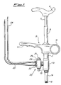
- 1 refers to the syringe reservoir for the liquid to be injected consisting of a cylindrical tubular body
- 2 refers to a piston provided with a guide ring 3 made of self-lubricating material having low friction coefficient, for instance teflon, tightly slidable inside the reservoir 1 thanks to a ring seal 4.
- piston 2 The upper part of piston 2 is articulated to the end of a stem 5 having the other end integral to a saddle-shaped operating handgrip.
- the upper portion of the stem 5 is concentrically housed in a cylindrical tubular sheath 7 slidable inside a cylindrical tubular guide 8, the lower end of which is fixed, for example by screw coupling, to the top of the reservoir 1.
- the central body of a handle is integral to the external surface of the upper portion of the reservoir 1, said central body comprising, on one side, a ring 10 for housing a thumb and, on the opposite side, an elongated element 11 with its lower side shaped in such a way as to accomodate the other fingers of the hand.
- a helicoidal spring 12 is housed surrounding the stem 5, one end of said spring is abutted against the bottom of the guide 8 while the opposite end is abutted against the base portion of the operating handgrip 6, said spring 12 being in the rest position when the stem 5 and relevant piston 2 are in the completely uplifted position.
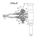
- a two-way valve body 13 To the lower end portion of reservoir 1 there is fixed, for example by screw coupling, the upper end of a two-way valve body 13, to the lower end of which is fixed, e.g. by screw coupling, an extension element 14, substantially cylindrical, axially bored, on the free end of which there is provided a connection 15, for example of the so-called american type, for fixing the needle (not shown).
- the valve body 13 has a first longitudinal duct 16 coaxial to and in communication with the reservoir 1 and with said axial hole in the extension element 14, and a second transversal duct 17, perpendicular to the first one and in communication therewith, axially machined in a side duct fitting 18 fixed to the valve body 13, for instance by screw coupling.
- Valve seats are respectively provided at the end of the first duct 16 connected with said axial hole in the extension element 14 and at the end of the second duct 17 connected with the first duct 16. These valve seats are equipped with seals, against which the relevant ball obturators 19 and 20 are constantly urged by helicoidal springs 21 and 22 respectively, so as to intercept any flow through said ducts, when the invention device is in its non operative state.
- a switching valve Secured to the side of the fitting 18 opposite to that associated to the valve body 13, for instance by screw coupling, there is a switching valve, generally referred to with 23.
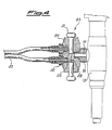
- the switching valve 23 as better shown in figure 3, comprises a valve body 24 wherein an axial duct 25 is formed, connected with the transversal duct 17 in the two-way valve body 23, on each end of which there is provided a internally threaded cylindrical housing where a relevant threaded nut is screwed, presenting a central hole coaxial and in communication with an enlarged cylindrical cavity 27 which, on its turn, is coaxial to and connected with the axial duct 25 in the valve body 24.
- a slide obturator 28 consisting of an intermediate rod-shaped portion the ends of which are in a single piece with relevant enlarged cylindrical terminal portions having substantially the same diameter as that of the axial duct 25, the tight sliding movement of said terminal portions in the hole 25 being secured by relevant ring seals 29.
- Each of said enlarged terminal portions of the box obturator 28 is secured to an end flange 30 and to the stem of a push-button 31 capable of sliding in a guided way in said central hole within the relevant nut 26.
- two fittings for tubes provided with relevant axial holes in communication with the axial duct 25 in the body 24 of the switching valve 23 each of which is connected to an end of a relevant flexible tube 33, the other end of said tube being connected to a relevant drawing tube 34 (see figure 1) coming from an appropriate container (not shown) for one of the relevant two liquids to be used in the dental operation.
- the spring 12 stress relieving will bring the stem 5 and relevant piston 2 upwards thus creating a sucking force within the reservoir 1 causing the removal of the ball 20 from its seat, against the action of the spring 22, thus allowing a communication between the axial duct 25 in the body 24 of the switching valve 23 and the longitudinal duct 16 through the transversal duct 17 in the two-way valve 13 body.
- the slide obturator 28 of the switching valve 23 is previously allowed to slide in the axial duct 25 as far as to bring one of the enlarged terminal portions to the intercepting position of the axial bore of the corresponding fitting for tubes 32, position determined by the counterboring of the relevant flange 30 on the annular shoulder created between the bottom of the cavity 27 and the corresponding end of the axial duct 25, connected through the relevant flexible tube 33 and the tube 34 to the container containing the liquid which has not to be drawn, said displacement of the box obturator 28 determining as a consequence the removal of the other enlarged terminal portion from the axial hole closing position of the corresponding fitting for tubes 32 so as to allow it to be connected, through the portion of the axial duct 25 of the switching valve 23 where there is said intermediate rod-shaped portion of the box obturator 28, the transversal duct 17 in the fitting 18 and the longitudinal duct 16 - which, as previously mentioned, are connected due to the removal of the ball obturator 22 from its
- a subsequent downward movement of the piston 2, according to the above described procedure, will create inside the reservoir 1 a compression of said liquid which determines the shut down of the ball valve 20, and therefore of the transversal duct 17 and simultaneously the opening of the communication between the longitudinal duct 16 and the axial bore in the extension element 14 following to the removal of the ball obturator 19 from its seat, against the action of the spring 21, so as to allow the ejection of said first liquid through the needle (not shown) secured to the connection 15 on the free end of the extension element 14.
- the slide obturator 23 is moved, acting on the other push-button 31, to the intercepting position of the axial bore of the fitting 32 connected through the relevant flexible tube 33 and tube 34 with the container of said first liquid, thus connecting the reservoir 1 according to the same above described procedure, with the container of the second liquid in order to allow the filling of the reservoir 1 with said second liquid upon releasing of the handle 6, which will allow the spring 12 to bring the stem 5 and relevant piston 2 again to the upper starting position with subsequent generation of a resulting sucking force in the reservoir 1.
- the present invention is not limited to the described embodiment, but it comprises any other possible variants in the configuration.
Landscapes
- Health & Medical Sciences (AREA)
- Dentistry (AREA)
- Veterinary Medicine (AREA)
- Public Health (AREA)
- General Health & Medical Sciences (AREA)
- Animal Behavior & Ethology (AREA)
- Life Sciences & Earth Sciences (AREA)
- Epidemiology (AREA)
- Nuclear Medicine, Radiotherapy & Molecular Imaging (AREA)
- Oral & Maxillofacial Surgery (AREA)
- Surgery (AREA)
- Neurosurgery (AREA)
- Neurology (AREA)
- Biomedical Technology (AREA)
- Engineering & Computer Science (AREA)
- Infusion, Injection, And Reservoir Apparatuses (AREA)
- Dental Tools And Instruments Or Auxiliary Dental Instruments (AREA)
- Cleaning By Liquid Or Steam (AREA)
- External Artificial Organs (AREA)
- Feeding, Discharge, Calcimining, Fusing, And Gas-Generation Devices (AREA)
Claims (6)
- Spritze zum Spülen von Zahnwurzelkanälen, die folgendes aufweist:
ein Reservoir (1), um eine zu injizierende Flüssigkeit aufzunehmen;
einen Kolben (2), der fähig ist, im Inneren des Reservoirs dicht zu gleiten;
einen Schaft (5), der ein Ende hat, das mit dem Kolben verbunden ist, während sein entgegengesetztes Ende an einem Betätigungsgriff (6) befestigt ist;
einen rohrförmigen Mantel (7), dessen oberes Ende mit dem Betätigungsgriff verbunden ist und in dem der obere Bereich des Schafts konzentrisch aufgenommen ist;
eine rohrförmige Führung (8), deren unteres Ende an dem oberen Ende des Reservoirs angebracht ist, um den Schaft (5) und den rohrförmigen Mantel (7) gleitend zu führen;
eine Schraubenfeder (12), um den Schaft (5) nach oben zu drängen, um den Kolbnen (2) aus der unteren Position in die angehobene Position im Inneren des Reservoirs (1) zurückkehren zu lassen;
einen Zweiwegeventilkörper (13), der mit dem Boden des Reservoirs verbunden ist und in dessen Körper ein Längskanal (16) vorgesehen ist, dessen oberes Ende in Verbindung mit dem Reservoir (1) steht und dessen unteres Ende mit einem ersten Verschlußelement (19) versehen ist, das durch eine erste Federeinrichtung (21) ständig in die Schließposition gedrängt wird, und mit einem Querkanal (17), der ein Ende hat, das in den Längskanal (16) mündet und mit einem zweiten Verschlußelement (20) versehen ist, das durch eine zweite Federeinrichtung (22) ständig in die Schließposition gedrängt wird;
ein Ansatzelement (14), das von dem unteren Ende des Zweiwegeventilkörpers (13) ausgeht, wobei eine Axialbohrung in Verbindung mit dem Längskanal (16) in dem Zweiwegeventilkörper an der stromabwärtigen Seite des ersten Verschlußelements (19) vorgesehen ist und am freien Ende einen Anschluß (15) zum Anbringen einer Injektionsnadel besitzt;
ein Schaltventil (23), das mit dem Zweiwegeventilkörper (13) verbunden ist und einen Körper (24) hat, in dem ein Längskanal (25) vorgesehen ist, der an einer ersten Seite mit dem Querkanal (17) des Zweiwegeventilkörpers und an der zweiten Seite mit einer der Axialbohrungen von Verbindungseinrichtungen (32) für Schläuche verbunden ist;
zwei flexible Schläuche (33), deren erste Enden mit jeweils relevanten der Verbindungseinrichtungen für Schläuche verbunden sind; und
einen Handgriff ((9), um die Spritze mit einer Hand zu greifen. - Spritze nach Anspruch 1,
wobei das untere Ende des Schafts (5) an dem Kolben (2) angelenkt ist. - Spritze nach Ansprüche 1 und 2,
wobei das erste (19) und das zweite Verschlußelement (20) in dem Längskanal (16) bzw. dem Querkanal (17) in dem Zweiwegeventilkörper (13) aus Kugelverschlüssen bestehen. - Spritze nach einem der Ansprüche 1 bis 3,
wobei die erste (21) und die zweite Federeinrichtung (22) in dem Zweiwegeventilkörper (13), die fähig sind, das erste und das zweite Verschlußelement (19, 20) ständig in die Schließposition des Längskanals (16) bzw. des Querkanals (17) zu drängen, aus schraubenförmigen Federn bestehen. - Spritze nach einem der vorhergehenden Ansprüche,
wobei das Verschlußelement (28) in dem Längskanals (25) des Schaltventils aus einem Gleitverschlußelement besteht, dessen vergrößerte Endbereiche mit einem dazwischenliegenden stabförmigen Bereich verbunden und mit Druckknöpfen (31) versehen ist. - Spritze nach einem der vorhergehenden Ansprüche,
wobei das Handgriff (9) einen zentralen Körper aufweist, der mit dem oberen Umfangsbereich des Reservoirs (1) integral ausgebildet und auf der einen Seite mit einem ringförmigen Element (10) und auf der entgegengesetzten Seite mit einem langgestreckten Griffelement (11) versehen ist.
Applications Claiming Priority (2)
| Application Number | Priority Date | Filing Date | Title |
|---|---|---|---|
| IT5260189 | 1989-01-16 | ||
| IT8952601U IT218502Z2 (it) | 1989-01-16 | 1989-01-16 | Siringa per il lavaggio dei canali radicolari dei denti |
Publications (2)
| Publication Number | Publication Date |
|---|---|
| EP0453493A1 EP0453493A1 (de) | 1991-10-30 |
| EP0453493B1 true EP0453493B1 (de) | 1993-09-22 |
Family
ID=11277307
Family Applications (1)
| Application Number | Title | Priority Date | Filing Date |
|---|---|---|---|
| EP90902229A Expired - Lifetime EP0453493B1 (de) | 1989-01-16 | 1990-01-15 | Spritze zum waschen von zahnwurzelkanälen |
Country Status (13)
| Country | Link |
|---|---|
| EP (1) | EP0453493B1 (de) |
| JP (1) | JPH04502718A (de) |
| AT (1) | ATE94745T1 (de) |
| AU (1) | AU4966490A (de) |
| DD (1) | DD298736A5 (de) |
| DE (1) | DE69003528T2 (de) |
| DK (1) | DK0453493T3 (de) |
| ES (1) | ES2044556T3 (de) |
| IT (1) | IT218502Z2 (de) |
| PL (1) | PL161976B1 (de) |
| PT (1) | PT92864A (de) |
| WO (1) | WO1990007911A1 (de) |
| ZA (1) | ZA90294B (de) |
Families Citing this family (6)
| Publication number | Priority date | Publication date | Assignee | Title |
|---|---|---|---|---|
| FR2666989A1 (fr) * | 1990-09-21 | 1992-03-27 | Castex Gerard | Dispositif d'irrigation ou de ponction en semi-continu. |
| WO2007110781A1 (en) | 2006-03-27 | 2007-10-04 | Roman Borczyk | Dental apparatus for irrigating root canals of teeth and method for irrigating root canals of teeth |
| EP2508217B1 (de) * | 2011-04-05 | 2019-09-04 | Kpr U.S., Llc | Anästhesiespritze |
| JP5965233B2 (ja) * | 2012-07-17 | 2016-08-03 | 一般財団法人化学及血清療法研究所 | 薬剤微量投与具 |
| JP6014395B2 (ja) * | 2012-07-17 | 2016-10-25 | 一般財団法人化学及血清療法研究所 | 薬剤微量投与具 |
| CN103990195B (zh) * | 2014-04-21 | 2016-04-13 | 王振彦 | 医用冲洗器 |
Family Cites Families (2)
| Publication number | Priority date | Publication date | Assignee | Title |
|---|---|---|---|---|
| US4109653A (en) * | 1977-02-22 | 1978-08-29 | George Kozam | Successive delivery multiple barrel syringe |
| US4381778A (en) * | 1981-05-27 | 1983-05-03 | George Kozam | Needle-loading multiple barrel syringe |
-
1989
- 1989-01-16 IT IT8952601U patent/IT218502Z2/it active
-
1990
- 1990-01-15 DK DK90902229.5T patent/DK0453493T3/da active
- 1990-01-15 AT AT90902229T patent/ATE94745T1/de not_active IP Right Cessation
- 1990-01-15 DE DE90902229T patent/DE69003528T2/de not_active Expired - Lifetime
- 1990-01-15 EP EP90902229A patent/EP0453493B1/de not_active Expired - Lifetime
- 1990-01-15 PT PT92864A patent/PT92864A/pt not_active Application Discontinuation
- 1990-01-15 ES ES90902229T patent/ES2044556T3/es not_active Expired - Lifetime
- 1990-01-15 JP JP2502573A patent/JPH04502718A/ja active Pending
- 1990-01-15 WO PCT/EP1990/000077 patent/WO1990007911A1/en not_active Ceased
- 1990-01-15 AU AU49664/90A patent/AU4966490A/en not_active Abandoned
- 1990-01-16 PL PL90283310A patent/PL161976B1/pl unknown
- 1990-01-16 ZA ZA90294A patent/ZA90294B/xx unknown
- 1990-01-16 DD DD90337136A patent/DD298736A5/de not_active IP Right Cessation
Also Published As
| Publication number | Publication date |
|---|---|
| JPH04502718A (ja) | 1992-05-21 |
| WO1990007911A1 (en) | 1990-07-26 |
| EP0453493A1 (de) | 1991-10-30 |
| PL161976B1 (pl) | 1993-08-31 |
| PL283310A1 (en) | 1991-04-22 |
| IT8952601V0 (it) | 1989-01-16 |
| DE69003528T2 (de) | 1994-03-31 |
| DK0453493T3 (da) | 1994-02-21 |
| ATE94745T1 (de) | 1993-10-15 |
| ZA90294B (en) | 1990-10-31 |
| ES2044556T3 (es) | 1994-01-01 |
| DD298736A5 (de) | 1992-03-12 |
| IT218502Z2 (it) | 1992-05-27 |
| PT92864A (pt) | 1990-07-31 |
| DE69003528D1 (de) | 1993-10-28 |
| AU4966490A (en) | 1990-08-13 |
Similar Documents
| Publication | Publication Date | Title |
|---|---|---|
| US5171146A (en) | Syringe for washing teeth root canals | |
| CA1192065A (en) | Dental instrument - pdl syringe | |
| US5759160A (en) | Blood sampling system | |
| EP1660173B1 (de) | Hämostasevorrichtung | |
| US8235256B2 (en) | Manual pump mechanism and delivery system | |
| US4381778A (en) | Needle-loading multiple barrel syringe | |
| US5256160A (en) | Medical device valving mechanism | |
| US4776840A (en) | Hand-held medical evacuator and irrigation device | |
| US4397640A (en) | Instrument for irrigation of a surgical site | |
| AU8025387A (en) | Back-fill syringe | |
| EP0453493B1 (de) | Spritze zum waschen von zahnwurzelkanälen | |
| US20060129107A1 (en) | Inflation syringe quick release apparatus | |
| WO1995013842A1 (en) | Syringes | |
| EP1800624B1 (de) | Federvorgespannte Injektionsvorrichtung für eine Intraokularlinse | |
| JP2017530858A (ja) | 液体吐出バルブを有するスパウト | |
| JP2001061772A (ja) | 内視鏡の流体制御装置 | |
| US20080257884A1 (en) | Cap for a Receptacle | |
| EP0474218A1 (de) | Spritze für Medizinalpaste, Füllverfahren und Injektionsvorrichtung für die Paste | |
| US5086782A (en) | Syringe for withdrawal of fluids | |
| CZ302391A3 (cs) | Stříkačka k promívání kořenových kanálků zubů | |
| GB2133288A (en) | Multiple barrel syringe | |
| US6126630A (en) | Apparatus for guiding a medical probe | |
| SU980815A1 (ru) | Устройство дл пипетировани жидкостей | |
| WO2025024198A1 (en) | One-handed insertion device for guidewire and improved syringe with guidewire | |
| CN121101638A (zh) | 一种可调力度的叩诊器 |
Legal Events
| Date | Code | Title | Description |
|---|---|---|---|
| PUAI | Public reference made under article 153(3) epc to a published international application that has entered the european phase |
Free format text: ORIGINAL CODE: 0009012 |
|
| 17P | Request for examination filed |
Effective date: 19910628 |
|
| AK | Designated contracting states |
Kind code of ref document: A1 Designated state(s): AT BE CH DE DK ES FR GB IT LI NL SE |
|
| 17Q | First examination report despatched |
Effective date: 19920525 |
|
| GRAA | (expected) grant |
Free format text: ORIGINAL CODE: 0009210 |
|
| ITF | It: translation for a ep patent filed | ||
| AK | Designated contracting states |
Kind code of ref document: B1 Designated state(s): AT BE CH DE DK ES FR GB IT LI NL SE |
|
| REF | Corresponds to: |
Ref document number: 94745 Country of ref document: AT Date of ref document: 19931015 Kind code of ref document: T |
|
| REF | Corresponds to: |
Ref document number: 69003528 Country of ref document: DE Date of ref document: 19931028 |
|
| ET | Fr: translation filed | ||
| REG | Reference to a national code |
Ref country code: ES Ref legal event code: FG2A Ref document number: 2044556 Country of ref document: ES Kind code of ref document: T3 |
|
| REG | Reference to a national code |
Ref country code: DK Ref legal event code: T3 |
|
| PLBE | No opposition filed within time limit |
Free format text: ORIGINAL CODE: 0009261 |
|
| STAA | Information on the status of an ep patent application or granted ep patent |
Free format text: STATUS: NO OPPOSITION FILED WITHIN TIME LIMIT |
|
| 26N | No opposition filed | ||
| PGFP | Annual fee paid to national office [announced via postgrant information from national office to epo] |
Ref country code: CH Payment date: 19941227 Year of fee payment: 6 |
|
| PGFP | Annual fee paid to national office [announced via postgrant information from national office to epo] |
Ref country code: SE Payment date: 19941230 Year of fee payment: 6 |
|
| PGFP | Annual fee paid to national office [announced via postgrant information from national office to epo] |
Ref country code: AT Payment date: 19950105 Year of fee payment: 6 |
|
| PGFP | Annual fee paid to national office [announced via postgrant information from national office to epo] |
Ref country code: BE Payment date: 19950109 Year of fee payment: 6 |
|
| PGFP | Annual fee paid to national office [announced via postgrant information from national office to epo] |
Ref country code: DK Payment date: 19950126 Year of fee payment: 6 |
|
| EAL | Se: european patent in force in sweden |
Ref document number: 90902229.5 |
|
| PGFP | Annual fee paid to national office [announced via postgrant information from national office to epo] |
Ref country code: NL Payment date: 19950131 Year of fee payment: 6 |
|
| PG25 | Lapsed in a contracting state [announced via postgrant information from national office to epo] |
Ref country code: DK Effective date: 19960115 Ref country code: AT Effective date: 19960115 |
|
| PGFP | Annual fee paid to national office [announced via postgrant information from national office to epo] |
Ref country code: GB Payment date: 19960115 Year of fee payment: 7 |
|
| REG | Reference to a national code |
Ref country code: DK Ref legal event code: EBP |
|
| PG25 | Lapsed in a contracting state [announced via postgrant information from national office to epo] |
Ref country code: SE Effective date: 19960116 |
|
| PGFP | Annual fee paid to national office [announced via postgrant information from national office to epo] |
Ref country code: DE Payment date: 19960125 Year of fee payment: 7 |
|
| PGFP | Annual fee paid to national office [announced via postgrant information from national office to epo] |
Ref country code: FR Payment date: 19960126 Year of fee payment: 7 |
|
| PG25 | Lapsed in a contracting state [announced via postgrant information from national office to epo] |
Ref country code: LI Effective date: 19960131 Ref country code: CH Effective date: 19960131 Ref country code: BE Effective date: 19960131 |
|
| PGFP | Annual fee paid to national office [announced via postgrant information from national office to epo] |
Ref country code: ES Payment date: 19960131 Year of fee payment: 7 |
|
| BERE | Be: lapsed |
Owner name: GUERCI SERGIO Effective date: 19960131 |
|
| PG25 | Lapsed in a contracting state [announced via postgrant information from national office to epo] |
Ref country code: NL Effective date: 19960801 |
|
| REG | Reference to a national code |
Ref country code: CH Ref legal event code: PL |
|
| NLV4 | Nl: lapsed or anulled due to non-payment of the annual fee |
Effective date: 19960801 |
|
| EUG | Se: european patent has lapsed |
Ref document number: 90902229.5 |
|
| PG25 | Lapsed in a contracting state [announced via postgrant information from national office to epo] |
Ref country code: GB Effective date: 19970115 |
|
| PG25 | Lapsed in a contracting state [announced via postgrant information from national office to epo] |
Ref country code: ES Free format text: LAPSE BECAUSE OF NON-PAYMENT OF DUE FEES Effective date: 19970116 |
|
| GBPC | Gb: european patent ceased through non-payment of renewal fee |
Effective date: 19970115 |
|
| PG25 | Lapsed in a contracting state [announced via postgrant information from national office to epo] |
Ref country code: FR Effective date: 19970930 |
|
| REG | Reference to a national code |
Ref country code: FR Ref legal event code: ST |
|
| REG | Reference to a national code |
Ref country code: ES Ref legal event code: FD2A Effective date: 19990503 |
|
| PG25 | Lapsed in a contracting state [announced via postgrant information from national office to epo] |
Ref country code: IT Free format text: LAPSE BECAUSE OF NON-PAYMENT OF DUE FEES;WARNING: LAPSES OF ITALIAN PATENTS WITH EFFECTIVE DATE BEFORE 2007 MAY HAVE OCCURRED AT ANY TIME BEFORE 2007. THE CORRECT EFFECTIVE DATE MAY BE DIFFERENT FROM THE ONE RECORDED. Effective date: 20050115 |