EP0453383B1 - Untersetzungsreibrollgetriebe der Bauart mit zwei Planetenradsätzen für hochtourig drehende Maschinen - Google Patents
Untersetzungsreibrollgetriebe der Bauart mit zwei Planetenradsätzen für hochtourig drehende Maschinen Download PDFInfo
- Publication number
- EP0453383B1 EP0453383B1 EP91440030A EP91440030A EP0453383B1 EP 0453383 B1 EP0453383 B1 EP 0453383B1 EP 91440030 A EP91440030 A EP 91440030A EP 91440030 A EP91440030 A EP 91440030A EP 0453383 B1 EP0453383 B1 EP 0453383B1
- Authority
- EP
- European Patent Office
- Prior art keywords
- wheels
- planetary
- friction
- masses
- hubs
- Prior art date
- Legal status (The legal status is an assumption and is not a legal conclusion. Google has not performed a legal analysis and makes no representation as to the accuracy of the status listed.)
- Expired - Lifetime
Links
Images

Classifications
-
- F—MECHANICAL ENGINEERING; LIGHTING; HEATING; WEAPONS; BLASTING
- F16—ENGINEERING ELEMENTS AND UNITS; GENERAL MEASURES FOR PRODUCING AND MAINTAINING EFFECTIVE FUNCTIONING OF MACHINES OR INSTALLATIONS; THERMAL INSULATION IN GENERAL
- F16H—GEARING
- F16H13/00—Gearing for conveying rotary motion with constant gear ratio by friction between rotary members
- F16H13/06—Gearing for conveying rotary motion with constant gear ratio by friction between rotary members with members having orbital motion
Definitions
- the present invention relates to a speed reducer with friction wheels in which the application force necessary for the latter is generated by its own operation.
- the technical sector of the invention is that of devices capable of capturing the rotary mechanical energy produced by any motive machine, but more particularly when the rotation speed of said machine is very fast, as is the case for turbines. steam and gas.
- compactness and lightness have very high rotational speeds as a counterpart, exceeding the limit of use of conventional existing coupling and reduction means, in particular those with gears.
- a device intended for this kind of applications is already known: it is an epicyloidal induction coupler-reducer for machines with very high rotational speed, described in European patent 0 161 194 in which the electromagnetic induction is mainly used to capture, at the cost of a slip, mechanical energy at very high speed of rotation in the primary part.
- the electromagnetic induction is mainly used to capture, at the cost of a slip, mechanical energy at very high speed of rotation in the primary part.
- electro-magnetic transmits the captured torque, but with the assistance of a purely mechanical rolling effect and rotary friction supported by the centrifugal force exerted on its satellite-inductors, which are relatively massive.
- the present invention aims to bring an improvement to this prior device by a simple design and better performance by avoiding electromagnetism, because the latter involves not only a delicate and expensive construction, but above all energy losses that cannot be reduced by sliding , Joule effect, hysteresis and eddy currents, therefore a significant release of heat which requires a means of cooling.
- the reducing device object of the present invention mainly implements friction wheels strongly applied against each other by the radial forces generated from the rotation of its movable assembly.
- friction wheels to capture and transmit torque
- many friction speed reduction devices are known, in particular from French patent 2,205,974 and its certificate of addition 2,211,088 which relate to a reducer planetary friction which also includes planets, but in which the force of application of the friction wheels comes from the tightening of elastic belts and not forces related to the operation of the device due to its rotation.
- the present invention essentially resides in the means of reversing the direction of the centrifugal force generated by the orbital rotation of the planets so that it s' also exerts, but centripetally, on the high-speed drive shaft located in the central position and that finally, all these primary and secondary friction wheels are applied energetically enough against each other to be able to effectively capture and transmit the torque- motor without slippage, at least up to a certain limit, fixed among other factors by the materials used and the dimensioning chosen.
- the teeth of the auxiliary gears doubling the friction wheels theoretically do not support any torque load, so that their failure threshold is carried over to higher rotational speeds, even with poor lubrication. It follows that the device according to the present invention can be mixed, that is to say with gears complementing the friction wheels in order to eliminate any risk of accidental or accidental slippage, especially during launching at low speed.
- the device according to the invention can also be used inversely as a speed multiplier, from any engine at low speed to drive receivers fast rotating such as centrifuges, centrifugal compressors, and others.
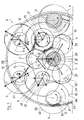
- the active rotating part of the reduction gear according to the invention is contained in a cylindrical casing-envelope 1 provided with two circular rolling tracks 10 of large diameter D5 each fixed concentrically in one of its two lateral covers 11.
- the central driving rotor 2 is supported at its two ends each furnished with a rolling ring of diameter D0 by three idle rollers 4 of diameter D1, arranged at 120 ° from one another, freely rotating on three axes 40 implanted in each of the two lateral cheeks 31.
- each end or hub 20 of the central drive rotor 2 rests on these idle rollers 4 at three points spaced 120 ° apart which constitute a rolling bearing, without any harmful passive resistance, because thus all friction actively participates in the transmission of movement.
- the wheels 62 of two outer planetary 6 neighbors but not in contact with the same planetary mass 5, are in contact with an intermediate idler 4 which kinematically links it to the central driving rotor 2.
- the central driving rotor 2 transmits by rotary friction its movement to the idle rollers 4 which transmit it to the wheels 62 therefore to the hubs 61 of the outer satellites 6 which roll in the two circular tracks of bearings 10 of the casing casing 1, thus causing the carrier cage - satellite 30.
- the ends of shafts or hubs of all the planetary ones have bearing rings similar to those of diameter D0 equipping the central driving rotor 2, but their diameters, d2 for the planetary-mass 5 and d3 for the external planetary 6 can be either equal to D0 is different, the diameter d3 intervening in the final reduction ratio, but not d2.
- the radial clearance of the idle rollers 4 on their axes 40 is such that the latter do not support any force, especially as these idle rollers 4 are self-centered by the symmetry of the radial forces exerted therein.
- These axes 40 therefore also have only a positioning role, so that the only passive resistances are located at the two ball bearings constituting the bearing bearings 34 of the cage 30 and at the six open housings 33 of each lateral cheek 31.
- idler rollers 4 as well as the large wheels 62 of the outer planet wheels 6 constitute intermediate wheels between the hubs 20 of the central drive shaft 2 and the hubs 51 of the planet wheels-masses 5, so that if the diameter d2 of the latter is equal at D0, the planetary-masses 5 rotate at the speed N0 of the central drive shaft 2, which may be arbitrary because, apart from their role synchronizing the wheels 62, they do not transmit the movement they receive to any other .
- the diameter D0 of the central driving rotor 2 being chosen, the value adopted for that D5 of the fixed raceway 10 determines the geometry of the assembly and most of the diameters.
- d3 smaller than D0, which implies to keep the same D1 to magnify D3 accordingly as well as d2 if RM must remain unchanged: because RM is such that the center of the planetary-mass 5 is found, all radial games caught up, at the center of the equilateral triangle formed by the axis of the central drive shaft 2 and those of the two outer planetary 6 neighbors.
- the largest possible diameter is obtained for the cylindrical mass M carried by each planetary-mass 5 and on which depends, with RM, the value of the centrifugal force generated.
- the choice of the diameters d2, d3, D3 and the orbital radius RM also determines the diameter D1 of the idle rollers 4.
- the radial clearance in the housings 35 of the ends of the shafts 51 of the planetary-masses 5 allows a sufficient reduction in RM to allow the establishment of all the wheels 62 of the outer planet wheels 6.
- their energetic support on the latter results in slight angular displacements and slightly different eccentricities, represented in FIG. 3 by a doubling in broken lines of the different circumferences.
- the centrifugal force used to apply the set of friction wheels against each other comes mainly from the drive in orbital rotation of the three planetary-masses 5, each of these three radial forces breaking down into two equal symmetrical forces, oblique at 60 °, all games caught up. While participating predominantly in the application of the hubs 61 of the outer sun gear 6 on their running track 10, the force resulting from these two oblique forces is transferred in a centripetal direction to the central drive shaft 2.
- the six outer planets 6 also driven in orbital rotation also generate a centrifugal force Fc '' proportional to their own mass m and eccentricity Rm but which, being radial, does not refer to the central driving shaft 2. Furthermore and construction, this mass m is not as large as that M of the planetary-masses 5, so that despite a much larger orbital drive radius, this second centrifugal effect is significantly smaller. Nevertheless, it is added to the application force received from the masses M by the hubs 61 rolling in the bore of the two fixed rolling tracks 10.
- each of the planetary-masses 5 being supported on the rolling support bearing formed by the large wheels 62 of the two outer planetary 6 neighboring, the centrifugal force developed radially breaks down into two equal vectors, oblique and symmetrical at 60 °, which tend to separate them from each other. It follows that each one tends to approach the next outer sun gear 6, which is also subject, with its neighbor, to the same spreading effect by the second sun gear, and so on for the others.
- this two-by-two bringing together of the outer planets 6 is limited by the presence, on each of the two wheels 62, of the idler roller 4 which is thus pushed towards the center by the two equal converging forces, the result of which is a force centripetal radial.
- the centrifugal force generated by each of the three planetary masses 5 is transmitted towards the center in three equal vectors offset by 120 ° by the idle rollers 4 resting on the rings 20 of the central drive rotor 2.
- the latter is then pinched as in a three-jaw chuck, so that while being supported by the idle rollers 4 as in a bearing it transmits their rotation at high speed by rotary friction effect.
- the rotary friction drive is done by the six outer planets 6 and also differently from the fact that the application force here combines two distinct centrifugal effects: that generated by the planetary-masses 5 and that specific to the mass m of each outside planet 6.
- the forces at play in the device according to the invention are as follows. Let the vector Fc of radial direction whose magnitude correspond to the centrifugal force generated by each planetary-mass 5: it breaks down into two equal and symmetrical vectors Fc ′, each directed towards the center of the outer planetary 6 located on either side other, forming with the initial vector Fc an angle of 60 °. The parallelogram of the forces thus being made up of two equilateral triangles, it follows that these two vectors Fc ′ are equal in magnitude to Fc.
- Each of the forces Fc ′ is transmitted to the outer planets 6 by pressing on their large wheels 62, therefore can be translated at their center, in the direction defined by the line of centers passing through the point of contact on the large wheel 62 of the hub 51 corresponding to the planetary-mass 5.
- the vectors Fc ′ then decompose into two forces: one Fa, radial, presses the hub 61 of this outer sun gear 6 on the raceway 10 and is exerted on the raceway 10, thus generating a support reaction Ra equal and of opposite direction; the other, Rp, exerts a push towards the neighboring outer planetary 6, perpendicular to the vector Fc ′ previously translated.
- the inductor satellites roll directly into the bore of the raceway, but here, with identical general dimensioning, the planetary-mass 5 are necessarily in a circular orbit reduced by about half, as well as their own diameter and therefore their mass: the centrifugal force to which they are subjected is therefore four times less.
- this planetary can be designed with a hollow body ballasted with very dense metal, for example lead.
- Make-up gears may be adopted for the sole purpose of avoiding slippage of the hubs 61 of the outer sun gear 6 during their rolling in the raceways 10, by means of, on each, a pinion 63 of pitch diameter d3 driving an internal gear 12 of pitch diameter D5.
- a train 65 of ratio d2 / D3 with a work rate is low if not zero.
- the present invention thus makes it possible to discharge the gear teeth of a reduction gear operating at very high rotational speeds, by transferring their work to friction wheels, so that they only have to play a role of synchronization and possible back-up.
- this system dodges any subjection of construction of fixed bearings. Moreover being rolling they are active here because the passive resistances participate in the transmission of the movement.
- the reduction ratio is established as follows: the kinematic chain starts from the central drive shaft 2 rotating at high speed N0 and ends, via the cage 30, at the output shaft 3 which runs at reduced speed N2. It passes successively through the friction wheels characterized by their diameter, from D0 to D1, from D1 to D3 which is integral with d3, from d3 to the cage 30 by the tangential thrust resulting from the rolling of d3 on D5: therefore do not intervene in the expression of the reduction ratio as the diameters D0, D3, d3 and D5, and not d2, nor D1.
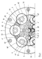
- the assembly in order to find concordant directions of rotation and to benefit from the best reduction ratio, the assembly is modified as follows.
- the two series of three idle rollers 4 serving as a bearing for the driving rotor are replaced by two series of three other rollers 4 ′ of much smaller diameter, that of the hubs of the planetary-masses. These rollers are still in rolling contact with the large wheels 62 of the outer sun gear 6 and constitute, as before, their spacing limiting stop. But because of their reduced diameter and the more eccentric position of their carrier axis, they are no longer in rolling contact with the hubs 20 of the central driving rotor 2, thus losing their former role of bearing carrier, assigned to two sets of six additional rollers 7.
- rollers 7 are intermediate wheels inserted in the annular space cleared around the central drive rotor 2, carried with play by pins implanted in each lateral cheek 31 of the cage 30. It follows that the number of rollers carrying the central drive rotor goes from two series of three at 120 ° to two series of six at 60 °, ie six rolling bearing points instead of three previously.
- the rolling contacts between these two series of six rollers 7 and the two series of three more eccentric rollers 4 ′ are located on each side: for a first group of three at 120 °, between the hubs 20 of the driving rotor 2 and the series of three idle rollers 4 ′ pushed centripetally each by a pair of large wheels 62 of two outer planet wheels 6 which are supported thereon; for the second group of the three others, also at 120 ° but alternated with the previous ones, between the hubs 20 of the central driving rotor 2 and the hubs 51 of the planet wheels-mass 5, all of these rollers 7 also being based on two series of rollers 4 ′ pushed centripetally each by a pair of large wheels 62 of two outer planetaries 6 consecutive.
- each of these two rollers 7 is supported under the effect of these thrusts, on the one hand on a hub 20 of the driving rotor 2, on the other hand on a hub 51 of a sun gear 5, so that these two hubs are opposed to their being further apart from one another.
- each hub of the driving rotor is thus clamped at six points at 60 ° by the same centripetal force resulting from the centrifugal force generated by the three planetary-masses.
- the result is the same as in the first embodiment, but the direction of rotation of the driven shaft becoming that of the leading the reduction ratio is more interesting, being increased by 2 to equal wheel diameters.
- the doubling of the number of contact points rolling on the driving rotor is beneficial, dividing by half the unit pressing pressure, so that the planetary-mass can be increased as much to increase the capacity of capture and transmission of the leading tree.
- gears can all be grouped on the same side, the organization of their lubrication is easier and the overall length is significantly reduced.
- this second embodiment may be preferred for these advantages, in particular if a higher reduction ratio is necessary.
Landscapes
- Engineering & Computer Science (AREA)
- General Engineering & Computer Science (AREA)
- Mechanical Engineering (AREA)
- Friction Gearing (AREA)
- General Details Of Gearings (AREA)
- Retarders (AREA)
Claims (5)
- Untersetzungsgetriebe mit Reibräder für hochtourig drehende Maschinen der Bauart mit doppeltem Umlaufgetriebe unter Verwendung eines angetriebenen Rotors zwischen einem zentralen Antriebsrad (2) und der Ausgangswelle (3), bei dem die mechanischen Effekte des rotierenden Reibantriebs durch kräftiges gegenseitiges Abwälzen der Reibräder erhalten wird, dadurch gekennzeichnet, daß die Angriffskräfte durch die Fliehkräfte erzeugt werden, die aus der orbitalen Drehung von Planetenmassen (5) der Masse M resultieren, welche mit Radialspiel um das Antriebsrad (2) angeordnet sind, diese Zentrifugalkraft die Planetenmassen (5) gegen äußere Planeten (6) geringerer Masse m drückt, welche durch Schlepprollen (4) in Drehung versetzt werden, die sich auf der Nabe (20) des Antriebsrads (2) abstützen, diese äußeren Planeten (6) mit ihren Naben (61) auf zwei kreisförmigen feststehenden Abrollspuren (10) sich abstützend abrollen, diese Naben (61) von Aufnahmen (33) umfaßt sind, die in den Seitenwangen (31) eines die Planeten lagernden Käfigs (30) ausgespart sind, welcher die äußeren Planeten (6) in axialer und radialer Richtung hält und welcher die Drehbewegung zur Ausgangswelle (3), mit der er einstückig ist, überträgt, die Planetenmassen (5) mit ihren Naben (51) sich abstützend auf den Radkränzen von Rädern (62) abrollen, die an den Naben (61) der äußeren Planeten (6) angebracht sind, derart, daß die durch die orbitale Drehung erzeugte Zentrifugalkraft dazu tendiert, die beiden auf zwei benachbarten Rädern (62) angeordneten Abstützungen zu spreizen, um somit die äußeren Planeten (6) paarweise voneinander zu entfernen und anzunähern, diese Verschiebung der äußeren Planeten (6) begrenzt wird durch das Vorhandensein der Schlepprollen (4), an welchen sich drehend abstützend die Räder (62) anliegen, diese Anordnung der Bauteile des Untersetzungsgetriebes in einem Aufbau von radialen zentripedalen Kräften resultiert, welcher das Antriebsrad (2) umschließt, den Betrieb der Aufnahme der mechanischen Energie durch rotierende Reibung und die Realisierung der Untersetzung der Geschwindigkeit gemäß dem theoretischen Bezug, der bestimmt wird durch die gewählten Durchmesser für die verschiedenen, ohne Gleiten zusammenwirkenden Reibräder, ermöglicht.
- Untersetzungsgetriebe nach Anspruch 1, dadurch gekennzeichnet, daß es anstelle der Schlepprollen (4) Schlepprollen (4') von kleinerem Durchmesser und zwischen den Rollen (4') und dem zentralen Antriebsrad (2) eingesetzte Zwischenrollen (7), welche durch in jede Seitenwange (31) des Käfigs (30) eingesetzte Achsen getragen werden, aufweist, die resultierende Zentripedalkraft in zwei quer und symmetrisch verlaufenden Richtungen auf zwei aufeinanderfolgende Zwischenrollen wirkt, den Erhalt des gleichen Drehsinns für das Antriebsrad (2) und die Ausgangswelle (3) ermöglicht und somit das Endverhältnis der Untersetzung ohne Änderung des Durchmessers der Planetenmassen (5) und der äußeren Planeten (6) erhöht.
- Untersetzungsgetriebe nach Anspruch 1 oder Anspruch 2, dadurch gekennzeichnet, daß die Planetenmassen (5) durch Hohlkörper gebildet werden, welche mit einem sehr schweren Metall, wie beispielsweise Blei ausgefüllt sind.
- Untersetzungsgetriebe nach einem der vorhergehenden Ansprüche, dadurch gekennzeichnet, daß die verschiedenen Reibräder aus einem mehr oder weniger harten Material bestehen, welches unter den Metallen oder den nichtmetallischen Materialien, homogen oder zusammengesetzt, bestehen.
- Untersetzungsgetriebe nach einem der vorhergehenden Ansprüche, dadurch gekennzeichnet, daß die benutzten Reibräder mit zusätzlichen Verzahnungen (65, 66, 67) des gleichen Durchmessers wie ihre wirksamen Durchmesser versehen sind.
Applications Claiming Priority (2)
| Application Number | Priority Date | Filing Date | Title |
|---|---|---|---|
| FR9005094 | 1990-04-17 | ||
| FR9005094A FR2660979B1 (fr) | 1990-04-17 | 1990-04-17 | Reducteur de vitesse a roues de friction. |
Publications (2)
| Publication Number | Publication Date |
|---|---|
| EP0453383A1 EP0453383A1 (de) | 1991-10-23 |
| EP0453383B1 true EP0453383B1 (de) | 1995-07-05 |
Family
ID=9395954
Family Applications (1)
| Application Number | Title | Priority Date | Filing Date |
|---|---|---|---|
| EP91440030A Expired - Lifetime EP0453383B1 (de) | 1990-04-17 | 1991-04-17 | Untersetzungsreibrollgetriebe der Bauart mit zwei Planetenradsätzen für hochtourig drehende Maschinen |
Country Status (6)
| Country | Link |
|---|---|
| US (1) | US5238459A (de) |
| EP (1) | EP0453383B1 (de) |
| AT (1) | ATE124763T1 (de) |
| DE (1) | DE69110956T2 (de) |
| FR (1) | FR2660979B1 (de) |
| WO (1) | WO1991016558A1 (de) |
Families Citing this family (15)
| Publication number | Priority date | Publication date | Assignee | Title |
|---|---|---|---|---|
| US5489244A (en) * | 1990-07-25 | 1996-02-06 | Yunzao Li | Centrifugal planetary friction transmission |
| NL9200731A (nl) * | 1992-04-22 | 1993-11-16 | Jacob Korf | Werkwijze en inrichting voor het niet-invasief bewaken van de concentratie van stoffen in bloed. |
| US7118512B2 (en) * | 2000-09-08 | 2006-10-10 | Iowa State University Research Foundation, Inc. | Self-actuating, traction-drive speed changer |
| KR100534198B1 (ko) * | 2005-06-24 | 2005-12-07 | 박종헌 | 동력전달장치 |
| DE102005049173B4 (de) * | 2005-10-14 | 2010-01-21 | Vojacek, Herbert, Prof. Dr.-Ing. | Reibradgetriebe |
| JP5060454B2 (ja) * | 2007-11-13 | 2012-10-31 | 京セラドキュメントソリューションズ株式会社 | トラクション動力伝達装置及びこれを搭載した画像形成装置 |
| US20100295782A1 (en) * | 2009-05-21 | 2010-11-25 | Yehuda Binder | System and method for control based on face ore hand gesture detection |
| CN108843760A (zh) | 2012-05-25 | 2018-11-20 | 詹尼斯高级技术有限公司 | 变速装置 |
| WO2014182546A2 (en) * | 2013-05-09 | 2014-11-13 | United Technologies Corporation | Turbofan engine front section |
| CN106523592B (zh) | 2015-09-09 | 2021-05-07 | Fev有限责任公司 | 用于平衡发动机壳体的旋转加速度的离心质量装置 |
| RU2611673C2 (ru) * | 2016-03-16 | 2017-02-28 | Александр Васильевич Дегтярев | Сцепление с универсальной самоцентрирующейся системой |
| RU2612357C2 (ru) * | 2016-04-10 | 2017-03-07 | Александр Васильевич Дегтярев | Передача с универсальной самоцентрирующейся системой с изменяемой геометрией |
| CN110671472A (zh) * | 2019-10-11 | 2020-01-10 | 杭州耐巡客车变速箱有限公司 | 轮边减速器及其装配方法 |
| CN110985609A (zh) * | 2020-01-07 | 2020-04-10 | 北京万创兴达科技有限公司 | 一种双齿轮组消隙减速器 |
| JP7350033B2 (ja) * | 2021-09-28 | 2023-09-25 | Toto株式会社 | トイレ装置 |
Family Cites Families (7)
| Publication number | Priority date | Publication date | Assignee | Title |
|---|---|---|---|---|
| US3254546A (en) * | 1962-11-14 | 1966-06-07 | Trw Inc | Toggle action planetary friction drive |
| US3364761A (en) * | 1963-07-19 | 1968-01-23 | Trw Inc | Torque sensitive multi-roller friction drive |
| US3267771A (en) * | 1964-03-09 | 1966-08-23 | Kendick Mfg Company Inc | Motion transmitting mechanism |
| FR1451418A (fr) * | 1965-07-15 | 1966-01-07 | Trw Inc | Dispositif de commande par frottement planétaire |
| US3367214A (en) * | 1966-02-17 | 1968-02-06 | Trw Inc | Double toggle action planetary friction drive |
| US3433099A (en) * | 1967-11-21 | 1969-03-18 | Trw Inc | Multi-roller friction drive with conical preload mechanism |
| FR2563063B1 (fr) * | 1984-04-12 | 1986-06-20 | Bech Jean | Coupleur-reducteur epicycloidal a induction pour machines a tres grande vitesse de rotation |
-
1990
- 1990-04-17 FR FR9005094A patent/FR2660979B1/fr not_active Expired - Lifetime
-
1991
- 1991-04-17 WO PCT/FR1991/000321 patent/WO1991016558A1/fr not_active Ceased
- 1991-04-17 AT AT91440030T patent/ATE124763T1/de not_active IP Right Cessation
- 1991-04-17 DE DE69110956T patent/DE69110956T2/de not_active Expired - Fee Related
- 1991-04-17 EP EP91440030A patent/EP0453383B1/de not_active Expired - Lifetime
- 1991-04-17 US US07/834,300 patent/US5238459A/en not_active Expired - Fee Related
Also Published As
| Publication number | Publication date |
|---|---|
| EP0453383A1 (de) | 1991-10-23 |
| FR2660979A1 (fr) | 1991-10-18 |
| DE69110956T2 (de) | 1996-04-04 |
| FR2660979B1 (fr) | 1992-07-10 |
| DE69110956D1 (de) | 1995-08-10 |
| US5238459A (en) | 1993-08-24 |
| WO1991016558A1 (fr) | 1991-10-31 |
| ATE124763T1 (de) | 1995-07-15 |
Similar Documents
| Publication | Publication Date | Title |
|---|---|---|
| EP0453383B1 (de) | Untersetzungsreibrollgetriebe der Bauart mit zwei Planetenradsätzen für hochtourig drehende Maschinen | |
| FR2708068A1 (fr) | Transmission à friction continûment variable. | |
| MC1115A1 (fr) | Transmission planetaire | |
| FR2634848A1 (fr) | Transmission a variation continue a courroie plate | |
| EP3908511B1 (de) | Untersetzungsgetriebe | |
| FR3128263A1 (fr) | Motoréducteur et cycle associé | |
| CN103502692B (zh) | 行星摩擦轮式无级变速器 | |
| FR2541405A1 (fr) | Transmission a roue conique plate en nutation | |
| FR2632037A1 (fr) | Transmission a variation continue a courroie plate | |
| FR2549178A1 (fr) | Roue libre d'accouplement de deux organes tournants | |
| FR2537684A1 (fr) | Mecanisme rotatif a came donnant de longues periodes de repos avec une rotation continue a l'entree | |
| FR2771153A1 (fr) | Reducteur epicycloidal ou cycloidal et articulation de robot equipee d'un tel reducteur | |
| FR2822198A1 (fr) | Moteur gravifique a differentiels de couples constants sur trains d'engrenages epicycloidaux | |
| FR3034484A1 (fr) | Dispositif de transmission | |
| FR3022857A1 (fr) | Dispositif pour l'entrainement en deplacement d'un vehicule automobile de type hybride et procede utilisant un tel dispositif. | |
| EP0319354B1 (de) | Antriebsvorrichtung eines Zahnrades mittels eines selbstausrichtenden fliegenden Ritzels | |
| EP0200205B1 (de) | Kupplung um zwei gleichachsige Wellen zu kuppeln mit teleskopischem Zwischenteil | |
| FR2606847A1 (fr) | Transmission mecanique a hypocycloide rectiligne | |
| BE372800A (de) | ||
| FR2704038A1 (fr) | Dispositif mécanique de réduction et de variation de vitesse de rotation. | |
| BE470848A (de) | ||
| BE351955A (de) | ||
| FR2770602A1 (fr) | Procede de transmission permettant une variation continue de vitesse de rotation par un engrenage toujours en prise | |
| FR3077612A3 (fr) | Train epicycloidal a geometrie variable | |
| MC2362A1 (fr) | Transmission mécanique par dérivations gyroscopiques |
Legal Events
| Date | Code | Title | Description |
|---|---|---|---|
| PUAI | Public reference made under article 153(3) epc to a published international application that has entered the european phase |
Free format text: ORIGINAL CODE: 0009012 |
|
| AK | Designated contracting states |
Kind code of ref document: A1 Designated state(s): AT BE CH DE DK ES FR GB GR IT LI LU NL SE |
|
| 17P | Request for examination filed |
Effective date: 19920422 |
|
| 17Q | First examination report despatched |
Effective date: 19931119 |
|
| GRAA | (expected) grant |
Free format text: ORIGINAL CODE: 0009210 |
|
| AK | Designated contracting states |
Kind code of ref document: B1 Designated state(s): AT BE CH DE DK ES FR GB GR IT LI LU NL SE |
|
| PG25 | Lapsed in a contracting state [announced via postgrant information from national office to epo] |
Ref country code: IT Free format text: LAPSE BECAUSE OF FAILURE TO SUBMIT A TRANSLATION OF THE DESCRIPTION OR TO PAY THE FEE WITHIN THE PRE;WARNING: LAPSES OF ITALIAN PATENTS WITH EFFECTIVE DATE BEFORE 2007 MAY HAVE OCCURRED AT ANY TIME BEFORE 2007. THE CORRECT EFFECTIVE DATE MAY BE DIFFERENT FROM THE ONE RECORDED.SCRIBED TIME-LIMIT Effective date: 19950705 Ref country code: NL Free format text: LAPSE BECAUSE OF FAILURE TO SUBMIT A TRANSLATION OF THE DESCRIPTION OR TO PAY THE FEE WITHIN THE PRESCRIBED TIME-LIMIT Effective date: 19950705 Ref country code: AT Effective date: 19950705 Ref country code: DK Effective date: 19950705 Ref country code: ES Free format text: THE PATENT HAS BEEN ANNULLED BY A DECISION OF A NATIONAL AUTHORITY Effective date: 19950705 Ref country code: GR Free format text: LAPSE BECAUSE OF FAILURE TO SUBMIT A TRANSLATION OF THE DESCRIPTION OR TO PAY THE FEE WITHIN THE PRESCRIBED TIME-LIMIT Effective date: 19950705 |
|
| REF | Corresponds to: |
Ref document number: 124763 Country of ref document: AT Date of ref document: 19950715 Kind code of ref document: T |
|
| REF | Corresponds to: |
Ref document number: 69110956 Country of ref document: DE Date of ref document: 19950810 |
|
| PG25 | Lapsed in a contracting state [announced via postgrant information from national office to epo] |
Ref country code: SE Effective date: 19951005 |
|
| GBT | Gb: translation of ep patent filed (gb section 77(6)(a)/1977) |
Effective date: 19951010 |
|
| NLV1 | Nl: lapsed or annulled due to failure to fulfill the requirements of art. 29p and 29m of the patents act | ||
| PG25 | Lapsed in a contracting state [announced via postgrant information from national office to epo] |
Ref country code: CH Effective date: 19960430 Ref country code: LI Effective date: 19960430 Ref country code: LU Free format text: LAPSE BECAUSE OF NON-PAYMENT OF DUE FEES Effective date: 19960430 Ref country code: BE Effective date: 19960430 |
|
| PLBE | No opposition filed within time limit |
Free format text: ORIGINAL CODE: 0009261 |
|
| STAA | Information on the status of an ep patent application or granted ep patent |
Free format text: STATUS: NO OPPOSITION FILED WITHIN TIME LIMIT |
|
| 26N | No opposition filed | ||
| BERE | Be: lapsed |
Owner name: BECH JEAN ANDRE Effective date: 19960430 |
|
| REG | Reference to a national code |
Ref country code: CH Ref legal event code: PL |
|
| PGFP | Annual fee paid to national office [announced via postgrant information from national office to epo] |
Ref country code: FR Payment date: 19990430 Year of fee payment: 9 |
|
| PG25 | Lapsed in a contracting state [announced via postgrant information from national office to epo] |
Ref country code: FR Free format text: LAPSE BECAUSE OF NON-PAYMENT OF DUE FEES Effective date: 20001229 |
|
| REG | Reference to a national code |
Ref country code: FR Ref legal event code: ST |
|
| REG | Reference to a national code |
Ref country code: FR Ref legal event code: RN |
|
| REG | Reference to a national code |
Ref country code: GB Ref legal event code: IF02 |
|
| PGFP | Annual fee paid to national office [announced via postgrant information from national office to epo] |
Ref country code: GB Payment date: 20040329 Year of fee payment: 14 Ref country code: DE Payment date: 20040329 Year of fee payment: 14 |
|
| REG | Reference to a national code |
Ref country code: FR Ref legal event code: FC |
|
| PG25 | Lapsed in a contracting state [announced via postgrant information from national office to epo] |
Ref country code: GB Free format text: LAPSE BECAUSE OF NON-PAYMENT OF DUE FEES Effective date: 20050417 |
|
| PG25 | Lapsed in a contracting state [announced via postgrant information from national office to epo] |
Ref country code: DE Free format text: LAPSE BECAUSE OF NON-PAYMENT OF DUE FEES Effective date: 20051101 |
|
| GBPC | Gb: european patent ceased through non-payment of renewal fee |
Effective date: 20050417 |