EP3908511B1 - Untersetzungsgetriebe - Google Patents
Untersetzungsgetriebe Download PDFInfo
- Publication number
- EP3908511B1 EP3908511B1 EP19894393.8A EP19894393A EP3908511B1 EP 3908511 B1 EP3908511 B1 EP 3908511B1 EP 19894393 A EP19894393 A EP 19894393A EP 3908511 B1 EP3908511 B1 EP 3908511B1
- Authority
- EP
- European Patent Office
- Prior art keywords
- motor
- diameter
- ring
- torque
- freewheel
- Prior art date
- Legal status (The legal status is an assumption and is not a legal conclusion. Google has not performed a legal analysis and makes no representation as to the accuracy of the status listed.)
- Active
Links
Images


Classifications
-
- B—PERFORMING OPERATIONS; TRANSPORTING
- B62—LAND VEHICLES FOR TRAVELLING OTHERWISE THAN ON RAILS
- B62M—RIDER PROPULSION OF WHEELED VEHICLES OR SLEDGES; POWERED PROPULSION OF SLEDGES OR SINGLE-TRACK CYCLES; TRANSMISSIONS SPECIALLY ADAPTED FOR SUCH VEHICLES
- B62M6/00—Rider propulsion of wheeled vehicles with additional source of power, e.g. combustion engine or electric motor
- B62M6/40—Rider propelled cycles with auxiliary electric motor
- B62M6/55—Rider propelled cycles with auxiliary electric motor power-driven at crank shafts parts
-
- B—PERFORMING OPERATIONS; TRANSPORTING
- B62—LAND VEHICLES FOR TRAVELLING OTHERWISE THAN ON RAILS
- B62K—CYCLES; CYCLE FRAMES; CYCLE STEERING DEVICES; RIDER-OPERATED TERMINAL CONTROLS SPECIALLY ADAPTED FOR CYCLES; CYCLE AXLE SUSPENSIONS; CYCLE SIDE-CARS, FORECARS, OR THE LIKE
- B62K19/00—Cycle frames
- B62K19/30—Frame parts shaped to receive other cycle parts or accessories
- B62K19/34—Bottom brackets
-
- B—PERFORMING OPERATIONS; TRANSPORTING
- B62—LAND VEHICLES FOR TRAVELLING OTHERWISE THAN ON RAILS
- B62M—RIDER PROPULSION OF WHEELED VEHICLES OR SLEDGES; POWERED PROPULSION OF SLEDGES OR SINGLE-TRACK CYCLES; TRANSMISSIONS SPECIALLY ADAPTED FOR SUCH VEHICLES
- B62M11/00—Transmissions characterised by the use of interengaging toothed wheels or frictionally-engaging wheels
- B62M11/04—Transmissions characterised by the use of interengaging toothed wheels or frictionally-engaging wheels of changeable ratio
- B62M11/14—Transmissions characterised by the use of interengaging toothed wheels or frictionally-engaging wheels of changeable ratio with planetary gears
Definitions
- the invention relates to mechanical speed reducers for electric motors.
- the invention relates in particular to mechanical reducers for electric motors used in bicycle assistance devices.
- an electrically assisted bicycle there must be two power transmission paths: a pedal-wheel path that transmits the torque generated by the cyclist, and a motor-wheel path. These two transmission paths must be able to overlap because in principle and to comply with the regulations, the motor must only provide torque to the wheel to the extent that the cyclist, himself, via the pedal, also provides torque to the wheel.
- the present invention relates more particularly to bicycles for which the assistance motor is placed in the central part of the bicycle, in particular being integrated into the crankset.
- phase 1 pedaling without assistance
- phase 2 pedaling with assistance
- phase 3 pedaling at a rotational speed higher than the maximum rotational speed generated by the motor
- phase 4 sudden stopping of pedaling by the cyclist
- phase 5 back-pedaling
- the motor-to-wheel drivetrain and the crankset-to-wheel drivetrain share the most common elements.
- the motor and pedals drive a common chainring, which is connected to the wheel by a standard bicycle chain with links.
- the motor must be able to connect mechanically to provide assistive motor torque at the crankset or chainring.
- a ratchet freewheel can become noisy while a roller freewheel will be quiet but will be heavy and will generate a higher friction torque during freewheeling.
- phase 5 there is a final functional phase of using an electrically assisted bicycle that poses problems in certain configurations (phase 5).
- the first of these configurations is when the cyclist wants to pedal in reverse to reposition his pedals, for example when approaching a bend so that they do not rub against the road or when the cyclist wants to start and position his call foot in a substantially horizontal position.
- the cyclist is able to provide a high back-pedaling torque, which will cause a high negative angular acceleration and therefore a very high negative torque because of the significant equivalent inertia of the motor, which risks destroying the gears of the geared motor.
- the reduction ratio between the rotation speed of the motor and the rotation speed of the pedal shaft is of the order of 100, which inevitably reduces the efficiency of this type of reducer, the reducer can even become irreversible and block as soon as the slightest lubrication or wear defect appears and this is why the patent WO 2016/128789 incorporates a torque limiter which allows the motor to be disconnected in the event of excessive torque to avoid breaking the teeth.
- This backpedaling phase is also often implemented in store when purchasing the bike. Indeed, it is common for an experienced cyclist to turn the cranks in reverse to estimate the friction losses of the drive chain (including the friction of the bottom bracket seals and bearings, the chain and its rollers as well as the bearings of the rear freewheel), which makes it possible to estimate the quality of the transmission friction.
- the freewheels used in electrically assisted bicycles of the prior art are simple freewheels that lock when a positive motor torque is applied to the input element (assist motor) and which is then transmitted to the output element (the crankshaft).
- the freewheel does not allow a negative torque to be transmitted in the opposite direction to the same element. input and will then start to rotate freely in this freewheel direction.
- the direction of rotation is the normal direction of use
- the direction of rotation is reversed on the output element, the pedal shaft, everything is reversed, that is to say that the freewheel will lock and transmit torque in reverse, thus driving the entire transmission chain in reverse, which has the disadvantages listed above.
- This type of assistance device comprises a motor whose stator and rotor have a tubular shape rotating coaxially around the pedal axle, it comprises a coaxial deformation wave reducer for transmitting the engine torque through an elliptical bearing driving by its outer ring a series of needles offset by a few teeth at each turn, thus making it possible to obtain in the example described a reduction ratio of 36.
- This type of assistance motor has the disadvantage of having two independent freewheels driving the transmission plate in parallel in the normal direction of travel, thus making it possible to transmit the driving power coming either from the pedals by a first freewheel, or from the assistance motor by a second freewheel to the rear wheel via the chain.
- this system includes a tubular torque sensor embedded on its side leading to the bottom bracket axle and embedded at its other end leading to the freewheel driving the chainring, thus making it possible to measure the cyclist's transmission torque.
- This torque sensor is therefore arranged coaxially between the central crank axle and the bearings of the motor rotor itself arranged inside the motor stator, thus leading to a very large external diameter, increasing the volume and mass of the assembly.
- the size of the external diameter also makes this type of bicycle very different from a non-assisted bicycle, which many practitioners consider it unsightly, in addition the size of the external diameter tends to move the rear wheel back and limit the crossing capacity of the bike whose engine casing could hit elements of the ground which is a real problem in off-road use.
- the objective of the invention is to provide a reducer for an electric motor, and in particular for an electrically assisted bicycle, which does not have the disadvantages of the reducers of the prior art.
- the objective of the invention is to propose a reducer which is as small and light as possible, while nevertheless having a high reduction ratio.
- said eccentric comprises two cams whose respective apices are diametrically opposed.
- the reducer comprises two eccentrics and three satellites; a first lateral satellite being mounted on a lateral cam of the first eccentric; a second lateral satellite being mounted on a lateral cam of the second eccentric while the central satellite is mounted on the two juxtaposed central cams of the first eccentric and the second eccentric.
- the reducer comprises two satellites, each of said two satellites being respectively rotatably mounted on one of said two cams by means of bearings.
- FIG. 1 illustrates an electrically assisted bicycle 1 incorporating an assistance system according to the present invention.
- this bicycle comprises a frame on which two wheels are fixed.
- the rear wheel 15 is the drive wheel and is driven by the crankset consisting of a pair of cranks 16, 16' and two pedals 17.
- the right crank comprises a star 161 whose ends are used to fix a toothed chainring 18.
- the transmission chain 19 19.
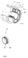
- FIG. 2 shows an exploded view of the assistance device according to a first embodiment of the invention.
- the bottom bracket 2 which is an integral part of the frame and connects a number of tubes which constitute it.
- the lower part of the oblique tube 13, the lower part of the seat tube 12 and the front ends of the rear dropouts 14 can be seen.
- the casing 21 containing a number of the components of the assistance device is intended to be housed inside the bottom bracket 2.
- the crankset itself comprises the left crank 16', a subassembly consisting of the shaft 4, the right crank 16 and the spider 161.
- the right crank 16 and the spider 161 are preferably a single piece permanently fixed to the shaft 4.
- the shaft 4 is preferably a hollow shaft having an external diameter greater than 23 mm, in order to offer a good mass/rigidity compromise. In the example described here, the outside diameter D4 of the shaft is 24 mm.
- a splined ring 44 is fixed on the shaft near the star 161. This splined ring 44 can be integrated into the axis 4 in different ways, some of which are detailed below.
- a first way to integrate this ring 44 into the shaft is to glue it onto the shaft 4 of a standard crankset using a high shear strength glue such as a two-component epoxy or an anaerobic glue, having taken care to prepare the surfaces beforehand according to the rules of the art (degreasing, possible sandblasting, etc.).
- a high shear strength glue such as a two-component epoxy or an anaerobic glue
- This grooved ring can also be an integral part of the shaft 4 or the right crank by being machined directly in the latter, in this case the shaft 4 must be designed and produced specifically from the start to be compatible with the invention.
- a third solution consists in mounting the ring 44 by shrink fitting onto the shaft 4, ensuring that the tightening between the shaft 4 and the splined ring is always sufficient to transmit the assistance torque with a safety margin.
- This shrink fitting can be associated with longitudinal grooves made in the bore of the splined ring in order to increase the transmittable torque, this solution requiring several hundredths of a mm of tightening is possible on a standard crankset if the tolerances of the shaft 4 are sufficiently reduced.
- This shrink fitting can be facilitated by cooling the shaft 4 and heating the splined ring before their assembly.
- this grooved ring 44 can be simply mounted as a pivot on the shaft 4 with very little play and have at its external end located against the right crank a disc or at least one radial arm, preferably very flat to minimize the axial size, and the end of the arm of which, radially distant from the central axis of the crankset, comprises an axially projecting zone cooperating with a face or an opening made in the right crank in order to be able to ensure a rotational connection between them, capable of transferring the assistance torque.
- the axially projecting area described above can be produced by means of an interchangeable part added to the arm of the grooved ring 44, the latter being able for example to be made of thermoplastic by 3D printing to be perfectly adapted to the design of the right crank.
- the disc located at the end of this grooved ring 44 can have one or more holes cooperating with small pins added to one or more holes made in the internal face of the right crank.
- Splines 45 are provided at the distal end of the shaft 4. These splines are used to transmit torque from the left crank 16' to the shaft 4.
- the left crank 16' is tightened against the shaft by means of screws 162 arranged perpendicular to the axis of rotation of the crankset X.
- a screw 46 makes it possible to ensure axial tightening between the 2 cranks through the shaft 4, in order to ensure a slight axial preload on the ball bearings.
- the chainring 18 is here made up of two toothed plates 181 and 182 which are fixed by screws to the ends of the star 161, this star is integral with the right crank arm, the shaft 4 is embedded at the center of the star.
- the central shaft is tubular with an external diameter D4 of approximately 24 mm and having a low thickness thus giving it a high level of resistance and rigidity while being very light
- the crank arms which are very stressed in bending and torsion by pedaling efforts have a closed hollow structure also giving them excellent specific rigidity (in relation to mass).
- Shaft 4 is directly embedded in a non-removable manner in the star at the base of the right crank, the absence of removable connecting elements such as screws, washers, nuts, keys, allows this subassembly to be lightened as much as possible.
- the bottom bracket shaft is generally made of steel or aluminum alloy metal but can in some cases be made of composite materials with preferably +/- 45° oriented bends to properly transmit the pedaling torque from the left crank.
- the cranks and the spider are generally made of aluminum alloy or composite materials in order to minimize their mass.
- crankset with a single-piece right crank with the axle has the major advantage of having an extremely short maintenance and assembly time, reducing assembly and repair costs.
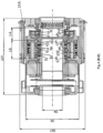
- FIG 3 shows a longitudinal section in plane AA of the casing 21 and the various components housed therein.
- the left compartment 211 receives the motor 3 and the measuring means 9. It is closed, on one side, by the left cover 23 and on the other by the central wall 213.
- the right compartment 212 is fixed against the left compartment 211 at the central wall 213. It receives the reducer 5 and the freewheel 6. It is closed by the right cover 22.
- the fixing of the right compartment 212 and the cover 22 is done by means of long screws 222 (visible in section at figure 4 ) which fix the cover 22 to the central wall 213 by sandwiching the right compartment.
- Measuring means 9 are housed inside the casing, these means in particular make it possible to control and command the motor.
- a first measuring means placed on the cover 22 which will not be described in detail makes it possible to measure the horizontal component of the force supported by the ball bearing 224 located on the crankset side. This measurement of the horizontal component is mainly impacted by the chain force and thus makes it possible to determine the chain force and therefore to go back to the total torque transmitted at the crankset, another patent application by the applicant describes how the cyclist's torque can thus be deduced from a measurement of total torque, so that the assistance torque is substantially proportional to the torque transmitted by the cyclist.
- a second measuring means is composed of a first angular sensor 91 associated with a first encoder disk 92 linked to the rotation of the crankshaft, it makes it possible in particular to detect the rotation of the crankshaft as well as its direction of rotation so that no assistance torque is provided in the event of backpedaling action as required by the current standard.
- This sensor will be useful mainly when the assistance is not active in order to know the speed and acceleration of the cyclist's pedaling, it will be particularly useful to detect the start of the assistance in order to be able to start it quickly, and also to detect the stopping of pedaling even if this can also be managed more finely by a second sensor.
- a third measuring means is also composed of a second angular sensor 93, associated with a second encoder 94, linked to the rotation of the motor by means of a measuring ring 37.
- a fourth means of measurement which is this time external to the housing, being located for example near the rear wheel, makes it possible to capture the forward speed of the bicycle in order to manage the cut-off of the assistance torque when the speed of the cycle approaches the programmed speed limit in order to comply with current legislation.
- the motor 3 is a three-phase electric motor of the multipolar brushless type with a central rotor comprising permanent magnets. It is powered by an electronic power controller itself powered by a battery (not shown) attached to the frame, or housed inside it.
- the rotor 32 is integral in rotation with a measuring ring 37 opposite a fixed sensor 93 relative to the casing 21, making it possible to precisely measure the angular position of the rotor relative to the stator, this information is necessary to allow the controller to perfectly manage the electrical control of the 3 phases according to the position of the rotor but also the assistance torque setpoint to be generated.
- This sensor can be magnetic, Hall effect type, induction or optical, but it is desirable to have an angular resolution of less than 360/(6.n) where n represents the number of pole pairs of the motor, for example for a motor with 10 pole pairs the angular resolution of this sensor must be well below 6° in order to properly switch the phases in the right place for trapezoidal switching, if we want to control the motor with a sinusoidal voltage it will then be necessary to further increase this resolution by at least a factor of five in order to properly phase the sinusoidal signal with the rotor angle.
- the motor 3 is generally annular in shape with a central recess of diameter greater than D4 so as to allow the shaft 4 to pass through it.
- the motor 3 consists of a stator 34 comprising the multiple windings of the three phases of the motor, inside which the rotor 32 rotates as well as the magnets 33 fixed to the latter.
- the rotor 32 is also integral in rotation with the motor member 31 whose function is to drive the shaft 4 through the reducer 5 and the freewheel 6.
- the motor member 31 comprises a first portion 311 mounted tightly in the rotor and a second portion 312 which constitutes the central part of the reducer 5.
- Two ball bearings, 313 and 314 ensure the centering of the motor member 31 in the casing 21.
- Two eccentrics 315 and 316 are fitted to the second portion 312 of the drive member 31 and tightened axially by a nut 318 so that the rotor 32, the drive member 31 and the eccentrics 315 and 316 are perfectly integral in rotation.
- Eccentrics 315 and 316 are identical and shown in perspective at figure 8 . They comprise a washer 3103 having on each of its sides a cam projecting. On the first side, the first cam, also called lateral cam 3101 projects over an angular amplitude ⁇ . It comprises a cylindrical internal surface 31012 of diameter D31 and a cylindrical external surface 31013 of diameter D504, but whose axis is eccentric by a value “e” relative to the axis of the internal surface 31012. It can be seen geometrically that the external diameter D504 must be greater than or equal to the sum of the internal diameter D31 and twice the eccentricity “e” (D504 ⁇ D31 + 2e) so that these two diameters do not intersect.
- the washer 3103 has on its second flank, the second cam, also called the central cam 3102 projecting over an angular amplitude ⁇ . It comprises a cylindrical internal surface 31022 of diameter D31 and a cylindrical external surface 31023 of diameter D504, and eccentric by a value “e” relative to the axis of the internal surface 31022.
- the apex 31015 of the lateral cam 3101 and the apex 31025 of the central cam 3102 are diametrically opposed, this amounts to saying that the two cams 3101 and 3102 are out of phase relative to the axis of their bore D31 by 180°, i.e. by half a turn.
- the thickness, in the radial direction, of the cams 3101 and 3102 is variable and that it has a minimum value at its 2 angular ends, for technical production reasons it is very delicate to end with a tab that is too thin and too fragile to be produced or even handled, which is why it is preferable to limit the angle ⁇ so that the minimum thickness of the cams is greater than a few tenths of a mm.
- the angle ⁇ is greater than 180° and can reach the value of 360°. In the latter case, the lateral and central cams protrude from the entire circumference of the sides of the washer. The smaller the angle ⁇ , the lighter the eccentrics will be, but the less good their centering will be. In the embodiment described here and which constitutes a preferred embodiment, the angle ⁇ is approximately 260°.
- the eccentrics 315 and 316 are mounted opposite each other in such a way that the central cam of the eccentric 315 is placed against the central cam of the eccentric 316, their respective apex having the same angular position.
- the eccentrics 315 and 316 are fixed and integral in rotation with the motor member 31. Indeed, these two eccentrics 315 and 316 are on the one hand centered by their bore D31 adjusted on the shaft of the second portion 312 of the motor shaft 31, but also by their external diameter D504 fitted into the bore of the common 521 ball bearing, this double centering thus requires them to remain in angular phase with respect to each other.
- eccentrics can be machined from aluminum alloy bars for small quantities or can be die-cast from Zamak-type zinc alloy for larger quantities, allowing very thin and very precise parts to be obtained at low cost.
- the reducer 5 is of the cycloidal type, that is to say that it comprises three separate components movable in rotation relatively and coaxially with respect to each other, one of the three being kept fixed.
- the one of the components which is connected to the motor is called the "input” of the reducer, while the other of the components which is in coaxial rotation with the input is called the “output” of the reducer.
- the input of the reducer 5 is constituted by the motor member 31 which, as explained above, is integral with the rotor 32.
- the output of the reducer 5 is constituted by a crown 55 and a drive ring 56 which is integrally connected to it. Between the output and the input of the reducer 5 is the planet carrier 57.
- the planet carrier 57 is, for this first embodiment, fixed in rotation, it mainly comprises a right flange 573 fixed to the central wall by means of six screws 572 and six spacers 571.
- the central wall 213 constitutes the left flange 574 of the planet carrier.
- a space, or cage, is thus delimited between the right flange 573 and the left flange 574 (i.e. the central wall 213). It is inside this space that the three satellites 51, 52 and 53 are placed.
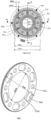
- figure 5 which is a cross-section along the cutting plane CC, shows that the six screws 572 and the six spacers 571 are regularly distributed around the circumference.
- the first and third satellites 51, 53 called lateral satellites, are identical and each constituted by a single toothed disk 50 visible in perspective at the figure 7 .
- the second satellite 52, called the central satellite, is made up of two identical and juxtaposed toothed disks 50.
- Each toothed disc 50 comprises a central bore 504 of diameter D504 and an external toothing 503 of primitive diameter D50. It further comprises a first series of six large openings 501, regularly distributed around the circumference. When the discs 50 are in place in the planet carrier, the large openings 501 are crossed by the screws 572 and the spacers 571.
- the toothed discs also include a second series of six circular openings 502, of diameter D502 regularly distributed around the periphery. The role of these circular openings 502 is visible from the view of the figure 4 which is a longitudinal section in the plane BB and of the figure 6 .
- Each of its circular openings 502 is crossed by one of the six small shafts 575 which are mounted between the right flange 573 and the left flange 574 using small ball bearings 576 and 577.
- the small shafts 575 are of a smaller diameter than the circular openings 502, they remain in contact with each other at all times. Since these small shafts 575 are highly stressed in rotary bending, they must be sufficiently strong. Nevertheless, and to limit the overall size of the device as well as the weight, they are chosen to have a diameter of approximately 4 mm.
- the small ball bearings 576 and 577 are necessary so that the rotation of the axes under load generates almost no friction losses harming the efficiency of the reducer, which would not be the case with a friction plain bearing.
- the satellites are mounted on the eccentrics 315 and 316 in the following manner: the lateral satellite 51 is mounted on the lateral cam 3101 of the eccentric 315 by means of a ball bearing 511. Similarly, the lateral satellite 53 is mounted on the lateral cam 3101 of the eccentric 316 by means of a ball bearing 531.
- the central satellite 52 which, it will be recalled, is twice as thick as the lateral satellites, because it comprises 2 juxtaposed discs 50, whereas the lateral satellites only comprise one, is mounted on the juxtaposed central cams of the eccentric 315 and the eccentric 316 by means of a ball bearing 521.
- the washers 3103 of the eccentrics 315, 316 serve as spacers between the internal rings of bearings 511, 521 and 531.
- the use of ball, needle or roller bearings is absolutely necessary so that the rapid rotation, under load, of the eccentrics relative to the toothed discs, which is more on a large diameter, generates very little loss and does not harm the mechanical efficiency of the reducer too much.
- the assembly of the satellites 51, 52 and 53 requires them to mesh with the internal toothing 551 of the crown 55, the primitive diameter of which is D55.
- the small shafts 575 which do not rotate in an overall movement around the axis X, and, moreover, in contact with the latter, their only possible movement is a circular translation movement of axis X whose trajectory is a circle of radius equal to "e".
- the movement of the satellites then generates a rotation along the axis X of the crown 55.
- the three satellites 51, 52 and 53 are not distributed regularly on the circumference, that is to say separated from each other by an angular gap of 120° for example.
- the mounting of the latter on the eccentrics 315, 316 which, as we have seen above, have cams whose apex is diametrically opposed, means that, at each instant, the angular position of the meshing point of the central satellite 52 with the crown 55 is diametrically opposed with that of the meshing points of the lateral satellites 51 and 53.
- This configuration has the effect of balancing all the forces and moments other than the torque about the X axis to which the three satellites subject the crown 55. Since, on the other hand, the crown 55 and the drive ring 56 connected to it are connected to the freewheel by means of an Oldham joint (see below), it can be said that the crown 55 is subjected to a pure moment of axis X.
- the rotation of the motor at a positive angular speed ⁇ 1 causes the rotation of the motor member 31 and the eccentrics 315 and 316 at the same speed.
- the eccentrics generate the specific movement of the satellites 51, 52 and 53, which drive the crown 55 in a positive rotation of speed ⁇ 2 much lower than ⁇ 1.
- a reduction ratio between 1/30 and 1/60 will be chosen. Above 1/30, the motor used must be capable of providing a significant torque, which implies that its magnetic circuit must also be large and therefore rather heavy. Using a reduction ratio lower than 1/60 implies using a motor that rotates very quickly and in which eddy current losses become significant, which considerably degrades its efficiency.
- the teeth shown in this first embodiment are straight involute teeth with a tooth module equal to 14/30 (approximately 0.467 mm), the outer ring 55 having 138 teeth therefore has a pitch diameter of 64.4 mm, the satellite pinions 51, 52 and 53 have 135 teeth and therefore have a pitch diameter of 63 mm, as these 2 gears have very similar pitch diameters, their meshing poses some design problems so that their teeth mesh without interference, thus a definition of standardized teeth, accessible to those skilled in the art, with a thrust angle of 20° and a tooth projection equal to the module and a tooth recess equal to 1.25 times the module, i.e.
- the satellite pinions are stressed at the level of the contact of the teeth but also in the circular openings 502 in which the small shafts 575 roll without sliding, this contact generates a relatively high contact pressure and requires a sufficient level of hardness of the small shafts 575 but also in the circular openings 502 of the satellite pinions 51, 52 and 53 which can be made of pretreated or hardened steel or of case-hardened steel or with nitriding very favorable to this type of contact.
- the pinions can be made of thermoplastic by adding a metal insert to each circular opening in order to better support the pressure of the small shafts, however, it will be necessary to widen the pinions so that the teeth are sufficiently resistant.
- the geared motor presented in this first embodiment allows to transmit a continuous assistance torque of 30 N.m at a rotation speed of 100 rpm which corresponds to a continuous power of approximately 315 Watt, its size is very limited since the external casing has a total length of 90 mm and its external diameter inserted in the frame measures only 79 mm.
- the length L5 of its reducer measures 23.5 mm while the total length L5 + L6 including the reducer and the freewheel mechanism measures only 36.7 mm.
- the mass of the reducer is only 345 g (excluding the freewheel mechanism) while the mass of the motor weighs 260 g and the total mass of the casing (motor, reducer, freewheel, measuring means) weighs approximately 950 g, therefore well below 1.5 kg.
- the geared motor presented in this first embodiment allows to transmit a continuous assistance torque of 30 Nm at a rotation speed of 100 rpm which corresponds to a continuous power of approximately 315 Watt, its size is very limited since the external casing has a total length of 90 mm and its external diameter inserted in the frame measures only 79 mm.
- the length L5 of its reducer measures 23.5 mm while the total length L5 + L6 including the reducer and the freewheel mechanism measures only 36.7 mm.
- the mass of the geared motor is only 345 g while the mass of the motor weighs 260 g and the total mass of the geared motor housing weighs less than 950 g.
- the arrangement of the two external disks which are eccentric in phase opposition relative to the two central twin disks ensures perfect dynamic balancing thus generating no vibration or parasitic noise.
- the output of the reducer is connected to the shaft 4 via the freewheel 6.
- an Oldham joint 64 is placed between these two elements (cf. figure 9 And 10 ).
- the Oldham seal 64 is in the form of a ring having on one of its faces two right protuberances 641, 641' diametrically opposed to each other, and on its other face two other left protuberances 642, 642', also diametrically opposed to each other. The diameter on which the right protuberances are placed and that on which the left protuberances are located are perpendicular.
- the right protuberances 641, 641' are received in the right housings 631, 631' provided in the freewheel body 63 having a shape complementary to the protuberances and the left protuberances 642, 642' are received in left housings 562, 562' provided in the drive ring 56.
- This Oldham seal can be made from a material with damping properties in order to filter out any meshing defects in the teeth as well as any torque variations generated by the motor in order to limit the noise emitted by the geared motor.
- the rotation of the motor is certainly globally coaxial with the central shaft of the pedal set but its bearing assembly does not refer anywhere to this central shaft of the pedal set, thus the centering of the rotor in the stator which must be very precise due to the very small air gap between the rotor and the stator is very well ensured and totally independent of the high loads which can stress and deform the central shaft.
- the Oldham joint here has the function of associating the two without superimposing hyperstatic constraints.
- the freewheel 6 will now be described in detail. It conventionally comprises two pawls 61 and a synchronizing ring 62.
- the pawls 61 are pivotally mounted about small axles 612 inside a housing 631 provided in the freewheel body 63.
- the pawls 61 pivot between an “engaged” position (not shown), in which their distal end is engaged with one of the teeth 652 provided on the ratchet 65, and a “disengaged” position shown in FIG. figure 11 (DD cut).
- a 62 synchronizing ring (cf. figure 12 ) synchronizes the tilting movement of the two pawls 61.
- This ring is connected to the pawls by two pins 613. It is pivotally mounted around the X axis by means of a rim 631 which guides it and holds it by clipping against the freewheel body 63.
- the synchronization ring 62 has a small amplitude of rotation relative to the freewheel body 63. Indeed, the synchronization ring is fixed to the pawls at a distance of a few millimeters from their pivot point so that the pivoting of the pawls 61 around the small axes 612 causes a displacement of a few degrees of the pins 613.
- the two pawls 61 are opposed at 180°, making it possible to balance the transmitted forces by transmitting, in theory, a pure torque without radial component, and by dividing substantially by two, the force transmitted by each of the pawls.
- the pawls preferably have one end with a engaging beak with teeth 652 provided on the ratchet 65.
- the synchronization ring 62 mounted as a pivot on the output of the reducer makes it possible to synchronize the rotation of these so that they engage well simultaneously.
- the freewheel also comprises means which enable the pawls 61 to be controlled, and in particular to be kept in the disengaged position.
- These means comprise a friction ring 72 and two pins 73.
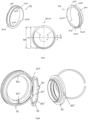
- the figure 13 shows the geometry and operation of the friction ring 72.
- the friction ring is an elastically deformable ring which comes into pre-stressed support on a fixed part of the device on at least two zones.
- the fixed part is a cylindrical barrel 221, projecting from the inner face of the cover 22.
- This ring comprises two diametrically opposed beads 721 arranged on the inner face of the ring. These beads are designed to slide on the inner surface of the barrel 221 coming from the cover 22.
- the friction ring 72 is integral in rotation with the synchronization ring 62 by means of two pins 73 inserted into two diametrically opposed radially oblong holes.
- the outside diameter between the two beads is, in the free state, slightly greater by approximately 0.5 mm than the outside diameter of the barrel 221.
- the installation of the friction ring will generate a certain ovalization of the latter, the geometry of this friction ring must be sized to generate two diametrically opposed radial forces during its ovalization of 0.5 mm without generating high stresses on the latter so that it can withstand this level of stress without creep throughout the service life of the product.
- a PBT or POM type material may be chosen to produce the ring because this friction part must have very good wear resistance, and very good elasticity as well as good behavior at operating temperature to guarantee very good stability of its tightening preload over the entire service life of the product.
- the transmission of torque between the ratchet 65 and the shaft 4 passes through the grooved ring 44 visible in perspective at Figure 5b
- the latter comprises a grooved portion 441 and a truncated portion 442, this truncated portion with an angle of approximately 15° is sufficiently open to be reversible and easily removable without the need for an extractor, but not too open either to ensure very good radial centering of the crankshaft under the moderate axial force of the screw 46 which made it possible to preload the assembly before the two screws 162 were locked.
- the cyclist wishes to be assisted with the electric motor. He has started the assistance device and possibly selected the assistance level.
- the rotor of the motor will start to rotate in the positive direction.
- the output of the reducer will then drive in the positive direction (normal pedaling direction marked with a + sign in the figures) at a speed 46 times lower than the motor, the synchronizing ring 62 which will also rotate in the same direction with it the friction ring 72, the friction of its two beads 721 on the barrel of the cover 22 will generate a friction torque which will be transmitted to the synchronizing ring 62.
- the freewheel is then engaged and the rotational coupling will be ensured very quickly after the small transient docking phase that we have just described, to ensure smooth and noiseless docking, it is preferable to limit the motor current for a short time at each resumption of assistance in order to ensure smooth and noiseless docking, to improve this docking phase it is also preferable to reduce the angular pitch of the teeth 652 of the ratchet 65, as can be seen on the section of the figure 6 , it is quite possible to integrate 32 teeth 652 on the ratchet 65 which allows to ensure a limited engagement step (11, 25 °) and therefore a flexible and fast docking.
- the two pawls are well engaged in a stable manner at the bottom of the teeth, this corresponds to state 1 of the freewheel 6, called assistance state, or to the pedaling mode with assistance (phase 2) when the cyclist does not pedal faster than the assistance provided by the motor.
- this disengagement of the pawls is linked to the relative direction of rotation between the crown of the reducer and the cover of the bottom bracket (fixed), so it will be possible to control the engagement of the pawls by controlling the direction of rotation of the motor so that it is sufficient to order a small reverse rotation of the motor to pivot the drive ring 56 at least a few degrees backwards, that is to say in the negative direction, to disengage the freewheel.
- a control microcontroller can detect this event either by a pedaling torque sensor (not shown) which suddenly becomes zero or negative, or by a zero crankset rotation speed detected by an angular sensor (not shown), or by a strong angular deceleration or by a reversal of the direction of rotation of the motor or the crankset and then order a reverse rotation of the motor with a greater rear acceleration than that of the cyclist for a fraction of a turn which will disengage the pawls and allow them to lift, this reverse gear can be stopped almost immediately and the freewheel will then remain in this stable disengaged state
- phase 1 the microcontroller will order a reverse rotation of the motor in order to place the freewheel in the disengaged state.
- the presence of the assistance device does not induce any additional friction or noise.
- FIG 14 shows an exploded view of the assistance device according to a second embodiment of the invention.
- the bottom bracket 2 which is an integral part of the frame and connects a number of tubes which constitute it.
- the lower part of the oblique tube 13, the lower part of the seat tube 12 and the front ends of the rear dropouts 14 can be seen.
- the casing 21 containing a number of the components of the assistance device is intended to be housed inside the bottom bracket 2.
- the crankset itself comprises the left crank 16', a subassembly consisting of the shaft 4, the right crank 16 and the star 161.
- the right crank 16 and the star 161 are preferably a single and same part permanently fixed to the shaft 4.
- a grooved ring 44 is fixed on the shaft near the star 161, the method of connection between the grooved ring 44 and the shaft 4 is completely identical to the first embodiment previously described
- Splines 45 are provided at the distal end of the shaft 4. These splines are used to transmit torque from the left crank 16' to the shaft 4.
- the left crank 16' is tightened against the shaft by means of screws 162 arranged perpendicular to the axis of rotation of the crankset X.
- a screw 46 makes it possible to ensure axial tightening between the 2 cranks through the shaft 4, in order to ensure a slight axial preload on the ball bearings exactly as for the first embodiment.
- the plate 18 here consists of two toothed plates 181 and 182 which are fixed by screws to the ends of the star 161 as for the first embodiment.
- FIG 15 shows a longitudinal section in the plane AA of the casing 21 and of the various components housed therein. It will be noted that the assistance device is shown in this view before the crankset is mounted therein, that is to say before the subassembly comprising the shaft 4, the chainring and the right crank is inserted into the central bore, the grooved ring 44 nevertheless being placed inside the ratchet 65.
- the casing 21, intended to be housed inside the housing 2, contains the majority of the elements of the assistance device. It consists of a tubular body 214 closed, on one side by the right cover 22 and on the other side by the left cover 23. It receives the motor 3, the measuring means 9, the reducer 5 and the freewheel 6.
- the motor 3 is an electric motor. It is preferably powered by a battery (not shown) attached to the frame, or housed inside it.
- the motor 3 consists of a stator 34 inside which the rotor 32 rotates as well as the magnets 33 fixed to the latter.
- the rotor 32 is integral in rotation with the drive member 31 whose function is to drive the shaft 4 through the reducer 5 and the freewheel 6.
- the drive member 31 comprises a first portion 311 mounted tightly in the rotor and a second portion 312 which constitutes the central part of the reducer 5.
- Two ball bearings, 313 and 314 ensure the centering of the drive member 31, on its right side the bearing 313 is centered on the end of the ratchet 65 and on its left side the bearing 314 is centered on the end of the ring in the casing 21.
- An eccentric 317 is mounted centered on the second portion 312 of the drive member 31 and tightened axially by a nut 318, so that the rotor 32, the drive member 31 and the eccentric 317 are perfectly integral in rotation.
- Eccentric 317 is perspective at the figure 18 . It comprises a washer 3173 having on each of its sides a cam projecting. On the first side, the first cam, also called right cam 3171 projects over an angular amplitude ⁇ . It comprises a cylindrical internal surface 31712 of diameter D31 and a cylindrical external surface 31713 of diameter D50, but whose axis is eccentric by a value “e” relative to the axis of the internal surface 31712. On the second side, the second cam, also called left cam 3172 projects over an angular amplitude ⁇ . It comprises a cylindrical internal surface 31722 of diameter D31 and a cylindrical external surface 31723 of diameter D50, and eccentric by a value “e” relative to the axis of the internal surface 31722.
- the diameters D31 and D51 are tangent allowing the second portion 312 of the drive member 31 to be inserted tangentially under the two ball bearings 511 and 521 ensuring their precise positioning despite a partial angular support of an angle ⁇ on each of their cams as visible in the section CC of the figure 17 .
- the apex 31715 of the right cam 3171 and the apex 31725 of the left cam 3172 are diametrically opposed so that the cams are out of phase by half a turn.
- the angle ⁇ is greater than 90° and can reach the value of 360°. In the latter case, the right and left cams protrude from the entire circumference of the sides of the washer. The smaller the angle ⁇ , the lighter the eccentrics will be.
- This configuration of the cam is identical to those described for the first embodiment of the invention. The difference lies in the fact that there are no longer two eccentrics for three satellites, but only one eccentric for two satellites.
- the reducer is of the cycloidal type and the input of the reducer is constituted by the drive member 31.
- the crown 55 is here the fixed element of the reducer and the output of the latter is constituted by the satellite carrier 57.
- the planet carrier 57 is rotatably mounted by means of two ball bearings 5781, 5782. It mainly comprises a right flange 573 and a left flange 574 connected to each other by means of six screws 572 and six spacers 571. A space, or cage, is thus delimited between the right flange 573 and the left flange 574. It is inside this space that the left satellite 51' and the right satellite 52' are placed.
- figure 18 which is a cross-section along the cutting plane CC, shows that the six screws 572 and the six spacers 571 are regularly distributed around the circumference.
- the two satellites 51' and 52' are each constituted by a single toothed disk with external teeth 50 similar to the disk with external teeth described for the first embodiment of the invention and visible in perspective at figure 19 .
- Each toothed disc 50 comprises a central bore 504 of diameter D504 and an external toothing 503 of primitive diameter D50. It further comprises a first series of six large openings 501, regularly distributed around the circumference. When the discs 50 are in place in the planet carrier, the large openings 501 are crossed by the screws 572 and the spacers 571.
- the toothed discs also include a second series of six circular openings 502, of diameter D502 regularly distributed around the periphery. The role of these circular openings 502 is visible from the view of the figure 16 which is a longitudinal section in the plane BB and of the figure 17 .
- Each of its circular openings 502 is crossed by one of the six small shafts 575 which are mounted between the right flange 573 and the left flange 574 using small ball bearings 576 and 577.
- the small shafts 575 are of diameter lower than that of the circular openings 502, they remain in contact with each other at all times, allowing linear contact without sliding, causing the continuous rotation of the small shafts 575 on themselves supported at their two ends by the small ball bearings 576 and 577, thus causing almost no loss of power at the level of this contact as for the first embodiment.
- the bearings 576, 577 are housed on each of the flanges 573, 574, therefore outside the disks 50. This minimizes the radial size and the compactness of the reducer.
- the satellites are mounted on the eccentric 317 in the following manner: the left satellite 51' is mounted on the left cam 3172 of the eccentric 317 by means of a ball bearing 511. Similarly, the right satellite 52' is mounted on the right cam 3171 of the eccentric 317 by means of a ball bearing 521.
- the use of ball, needle or roller bearings is absolutely necessary so that the rapid rotation, under load, of the eccentrics relative to the toothed disks, which is moreover on a large diameter, generates only very little loss and does not harm the mechanical efficiency of the reducer too much.
- the washer 3173 of the eccentric 317 serves as a spacer between the internal rings of the bearings 511 and 521, and a nut 318 screwed into the end of the drive member axially tightens this entire assembly in order to drive the eccentrics with the drive member by adhesion, we can note that the input torque of the reducer is here very low compared to the output torque since it only represents approximately 2% of the output torque (reduction ratio close to 50).
- the assembly of the satellites 51' and 52' requires them to mesh with the internal toothing 551 of the crown 55, the primitive diameter of which is D55.
- the rotational movement of the eccentric requires an off-center rotation of the satellites.
- cams 3171 and 3172 have their respective apices diametrically opposed. So that, at each instant, the angular position of the meshing point of the left satellite 51' with the crown 55 is diametrically opposed to that of the meshing point of the right satellite 52', thus the center of gravity of the pairs of parts is always on the central axis X but this is not sufficient to properly balance the system since it is also necessary for one of the main axes of inertia to be aligned with the axis of rotation, thus in order to dynamically balance the pair of eccentric subassemblies (eccentric 317/bearings 511-521/satellites 51'-52'), it is necessary to add masses or to remove balancing holes 38 and 39 whose overall center of gravity must also remain centered on the axis but which must also compensate for the dynamic moment caused by the rotation of the satellites whose respective median planes are axially offset. To facilitate balancing, it is therefore desirable to lighten the two eccentric subas
- the rotation of the motor at a positive angular speed ⁇ 1 causes the rotation of the motor member 31 and the eccentric 317 at the same speed.
- the eccentrics generate the specific movement of the satellites 51' and 52', which drive the satellite carrier 57 in a negative rotation of speed w2 much lower than w1.
- a reduction ratio will be chosen, in absolute value, between 1/30 and 1/60. Above 1/30, the motor used must be capable of providing a significant torque, which implies that its magnetic circuit must also be large and therefore rather heavy.
- the use of a reduction ratio lower than 1/60 implies the use of a motor that rotates very quickly and in which eddy current losses become significant, which considerably degrades its efficiency, the best overall compromise is therefore also in this reduction ratio range.
- the freewheel 6 will now be described in detail. In principle, it is similar to that described for the first embodiment except that it is driven by the planet carrier 57, and not by the crown 55.
- the freewheel body 63 is fixed to the planet carrier 57 by the screws 572. It conventionally comprises two pawls 61 and a synchronizing ring 62.
- the pawls 61 are pivotally mounted inside a housing 631 formed in the freewheel body 63.
- the pawls 61 pivot between an “engaged” position (not shown), in which their distal end is engaged with one of the teeth 652 formed on the ratchet 65, and a “disengaged” position shown in FIG. figure 20 (DD cut).
- a 62 synchronizing ring (cf. figure 21 ) synchronizes the tilting movement of the two pawls 61.
- This ring is connected to the pawls by two pins 613. It is pivotally mounted around the X axis by means of a rim 631 which guides it and holds it by clipping against the freewheel body 63.
- the synchronization ring 62 has a small amplitude of rotation relative to the freewheel body 63.
- the synchronization ring is fixed to the pawls at a distance of a few millimeters from their pivot point so that the pivoting of the pawls 61 around the small axes 612 causes a displacement of a few degrees of the pins 613.
- the two pawls 61 are opposed at 180° allowing the transmitted forces to be balanced by transmitting, in theory, a pure torque without radial component, and by substantially dividing by two, the force transmitted by each of the pawls.
- the pawls preferably have one end with a beak engaging with teeth 652 arranged on the ratchet 65.
- the synchronization ring 62 mounted as a pivot on the output of the reducer makes it possible to synchronize the rotation of the latter so that they engage well simultaneously.
- the freewheel also comprises means which enable the pawls 61 to be controlled, and in particular to be kept in the disengaged position.
- These means comprise a friction ring 72 and two pins 73.
- the figure 22 shows the geometry and operation of the friction ring 72.
- the friction ring is an elastically deformable ring which comes into pre-stressed support on a fixed part of the device on at least two zones.
- the fixed part is a cylindrical barrel 221, projecting from the inner face of the cover 22.
- This ring comprises two diametrically opposed beads 721 arranged on the inner face of the ring. These beads are designed to slide on the inner surface of the barrel 221 coming from the cover 22.
- the friction ring 72 is integral in rotation with the synchronization ring 62 by means of two pins 73 inserted into two diametrically opposed radially oblong holes.
- the outside diameter between the two beads is, in the free state, slightly greater by approximately 0.5 mm than the outside diameter of the barrel 221.
- the installation of the friction ring will generate a certain ovalization of the latter, the geometry of this friction ring must be sized to generate two diametrically opposed radial forces during its ovalization of 0.5 mm without generating high stresses on the latter so that it can withstand this level of stress without creep throughout the service life of the product.
- a PBT or POM type material may be chosen to produce the ring because this friction part must have very good wear resistance, and very good elasticity as well as good behavior at operating temperature to guarantee very good stability of its tightening preload over the entire service life of the product.
- the geared motor presented in this second embodiment makes it possible to transmit a continuous assistance torque of 30 Nm at a rotation speed of 100 rpm, which corresponds to a continuous power of approximately 315 Watts; its size is very limited since the external casing has a total length of 90 mm and its external diameter inserted into the frame measures only 79 mm.
- the length L5 of its reducer measures 23.15 mm while the total length L5+L6 including the reducer and the freewheel mechanism measures only 29.4 mm.
- the mass of the reducer (excluding the freewheel mechanism) is only 250 g while the mass of the motor weighs 260 g and the total mass of the casing 21 including the motor, the reducer, the freewheel and the measuring means weighs approximately 930 g, therefore well below 1.5 kg.
Landscapes
- Engineering & Computer Science (AREA)
- Chemical & Material Sciences (AREA)
- Combustion & Propulsion (AREA)
- Mechanical Engineering (AREA)
- Transportation (AREA)
- Retarders (AREA)
- Connection Of Motors, Electrical Generators, Mechanical Devices, And The Like (AREA)
- Devices For Conveying Motion By Means Of Endless Flexible Members (AREA)
- Transmission Devices (AREA)
Claims (4)
- Mechanisches Untersetzungsgetriebe (5) mit einem Rotor (32), einem äußeren Kranz (55) mit einem Teilkreisdurchmesser D55 und einem Planetenträger (57), der mindestens ein Planetenrad (51, 52, 53, 51', 52') mit einem Teilkreisdurchmesser D50 umfasst, das dazu vorgesehen ist, sich innerhalb des Kranzes mit einer Exzentrizität des Wertes "e" zu drehen, der gleich der Differenz zwischen dem Durchmesser D55 und dem Durchmesser D50 ist; e = 1/2(D55 - D50); wobei das mindestens eine Planetenrad über einen Exzenter (315, 316, 317), der mindestens einen Nocken (3101, 3102, 3171, 3172) aufweist, drehbar am Rotor (32) montiert ist, dadurch gekennzeichnet, dass der Nocken eine zylindrische Innenfläche (31012, 31022, 31712, 31722) mit einem Durchmesser D31 und eine zylindrische Außenfläche (31013, 31023, 31713, 31723) mit einem Durchmesser D504 umfasst, wobei der Durchmesser D504 gleich der Summe des Durchmessers D31 und der doppelten Exzentrizität "e" ist; D504 = D31 + 2e.
- Untersetzungsgetriebe nach Anspruch 1, dadurch gekennzeichnet, dass der Exzenter (315, 316, 317) zwei Nocken (3101, 3102, 3171, 3172) aufweist, deren jeweilige Apex (31015, 31025, 31715, 31725) diametral gegenüberliegen.
- Untersetzungsgetriebe nach dem vorangehenden Anspruch, dadurch gekennzeichnet, dass es zwei Planetenräder (51', 52') umfasst, wobei jedes der beiden Planetenräder jeweils drehbar über ein Lager an einem der beiden Nocken (3171, 3172) montiert ist.
- Untersetzungsgetriebe nach Anspruch 2, dadurch gekennzeichnet, dass es zwei Exzenter (315, 316) und drei Planetenräder (51, 52, 53) umfasst, wobei ein erstes seitliches Planetenrad (51) an einem seitlichen Nocken (3101) des ersten Exzenters (315) montiert ist, ein zweites seitliches Planetenrad (53) an einem seitlichen Nocken (3101) des zweiten Exzenters (316) montiert ist, während das mittlere Planetenrad (52) an den beiden nebeneinanderliegenden mittleren Nocken (3102) des ersten Exzenters (315) bzw. des zweiten Exzenters (316) montiert ist.
Applications Claiming Priority (2)
| Application Number | Priority Date | Filing Date | Title |
|---|---|---|---|
| FR1900164A FR3091516B1 (fr) | 2019-01-08 | 2019-01-08 | Dispositif d’assistance électrique pour vélo |
| PCT/FR2019/000196 WO2020144411A2 (fr) | 2019-01-08 | 2019-12-03 | Réducteur |
Publications (2)
| Publication Number | Publication Date |
|---|---|
| EP3908511A2 EP3908511A2 (de) | 2021-11-17 |
| EP3908511B1 true EP3908511B1 (de) | 2024-10-09 |
Family
ID=67514709
Family Applications (2)
| Application Number | Title | Priority Date | Filing Date |
|---|---|---|---|
| EP19894393.8A Active EP3908511B1 (de) | 2019-01-08 | 2019-12-03 | Untersetzungsgetriebe |
| EP19835435.9A Withdrawn EP3908510A1 (de) | 2019-01-08 | 2019-12-03 | Mechanisches untersetzungsgetriebe |
Family Applications After (1)
| Application Number | Title | Priority Date | Filing Date |
|---|---|---|---|
| EP19835435.9A Withdrawn EP3908510A1 (de) | 2019-01-08 | 2019-12-03 | Mechanisches untersetzungsgetriebe |
Country Status (3)
| Country | Link |
|---|---|
| EP (2) | EP3908511B1 (de) |
| FR (1) | FR3091516B1 (de) |
| WO (2) | WO2020144411A2 (de) |
Families Citing this family (6)
| Publication number | Priority date | Publication date | Assignee | Title |
|---|---|---|---|---|
| CN111959672A (zh) * | 2020-08-18 | 2020-11-20 | 姜立人 | 一种适用于自行车的二速自动变速器 |
| ES2932876A1 (es) * | 2021-07-20 | 2023-01-27 | Morales Fernando Cuesta | sistema de transmisión variable para bicicletas con asistencia eléctrica |
| FR3128266B1 (fr) | 2021-10-14 | 2024-02-09 | Mavic Group | Motoréducteur et cycle associé |
| FR3128265B1 (fr) * | 2021-10-14 | 2024-02-02 | Mavic Group | Dispositif de transmission de couple, dispositif d’assistance électrique et cycle associé |
| FR3128263B1 (fr) | 2021-10-14 | 2023-09-22 | Mavic Group | Motoréducteur et cycle associé |
| TWI834361B (zh) * | 2022-10-28 | 2024-03-01 | 車王電子股份有限公司 | 同軸式自行車中置動力裝置 |
Family Cites Families (16)
| Publication number | Priority date | Publication date | Assignee | Title |
|---|---|---|---|---|
| US4117746A (en) * | 1976-10-29 | 1978-10-03 | Compudrive Corporation | Orbital drive mechanism |
| JP3708526B2 (ja) | 2003-02-18 | 2005-10-19 | 株式会社シマノ | 自転車用クランク組立体 |
| JPH07117128B2 (ja) * | 1991-06-17 | 1995-12-18 | 株式会社松村ギアー製作所 | ハイポサイクロイド減速装置 |
| ATE161930T1 (de) * | 1991-08-13 | 1998-01-15 | Sumitomo Heavy Industries | Getriebekonstruktion nach dem zykloideprinzip |
| US6296072B1 (en) * | 1999-01-20 | 2001-10-02 | Opti-Bike Llc | Electric bicycle and methods |
| JP5818814B2 (ja) * | 2010-01-22 | 2015-11-18 | フォスター・アセッツ・コーポレーション | トルクセンサーを内蔵したモーター |
| EP2538112B1 (de) * | 2010-02-15 | 2014-10-01 | JTEKT Corporation | Planetengetriebevorrichtung mit internem schwingkontakt und drehantriebsvorrichtung |
| EP2502819A1 (de) | 2011-03-25 | 2012-09-26 | Gruber Antrieb GmbH & Co KG | Elektrischer Hilfsantreib für Fahrräder |
| US8757311B2 (en) | 2011-06-10 | 2014-06-24 | Yet Chan | Motorized driving device |
| GB201203211D0 (en) | 2012-02-24 | 2012-04-11 | Macmartin Neil | Vehicle gearing system |
| EP4400400A3 (de) | 2013-03-20 | 2025-01-22 | TQ-Systems GmbH | Harmonisches pinring-getriebe |
| EP2784347A1 (de) * | 2013-03-25 | 2014-10-01 | Spinea s.r.o. | Getriebe |
| DE202014103469U1 (de) * | 2014-07-28 | 2015-10-29 | Brose Fahrzeugteile Gmbh & Co. Kommanditgesellschaft, Coburg | Antriebseinrichtung für ein Elektrorad |
| EP3256375B1 (de) | 2015-02-10 | 2020-10-28 | S.C.P. Typhoon | Doppelmotorische antriebseinheit und verfahren zur montage der einheit an einen fahrradrahmen |
| US9783262B2 (en) * | 2015-04-07 | 2017-10-10 | Tangent Motor Company | Electric drive unit |
| CN207311751U (zh) * | 2017-10-09 | 2018-05-04 | 天津迪思科博科技发展有限公司 | 力矩检测传动装置及其应用该装置的电动自行车中置电机 |
-
2019
- 2019-01-08 FR FR1900164A patent/FR3091516B1/fr active Active
- 2019-12-03 WO PCT/FR2019/000196 patent/WO2020144411A2/fr not_active Ceased
- 2019-12-03 WO PCT/FR2019/000195 patent/WO2020144410A1/fr not_active Ceased
- 2019-12-03 EP EP19894393.8A patent/EP3908511B1/de active Active
- 2019-12-03 EP EP19835435.9A patent/EP3908510A1/de not_active Withdrawn
Also Published As
| Publication number | Publication date |
|---|---|
| WO2020144411A2 (fr) | 2020-07-16 |
| EP3908510A1 (de) | 2021-11-17 |
| FR3091516B1 (fr) | 2022-07-15 |
| FR3091516A1 (fr) | 2020-07-10 |
| EP3908511A2 (de) | 2021-11-17 |
| WO2020144411A3 (fr) | 2020-10-29 |
| WO2020144410A1 (fr) | 2020-07-16 |
Similar Documents
| Publication | Publication Date | Title |
|---|---|---|
| EP3908511B1 (de) | Untersetzungsgetriebe | |
| EP3908512B1 (de) | Elektrische unterstützungsvorrichtung für ein fahrrad | |
| EP3880981B1 (de) | Elektrisches fahrradunterstützungsgerät | |
| WO2017187056A1 (fr) | Réducteur cycloïdal à denture hélicoïdale pour direction assistée | |
| EP2707248B1 (de) | Motorisiertes gelenk für fahrzeugsitz | |
| WO2014086727A1 (fr) | Dispositif d'assistance electrique pour velo et velo a assistance electrique equipe dudit dispositif | |
| FR3143078A1 (fr) | Dispositif de transmission de couple, dispositif d’assistance électrique et cycle associé | |
| EP2199198B1 (de) | Getriebeeinheit für ein Fahrrad | |
| FR3128263A1 (fr) | Motoréducteur et cycle associé | |
| FR3079811A1 (fr) | Reducteur pour systeme d'assistance electrique pour cycle | |
| FR3079810A1 (fr) | Systeme d'assistance electrique pour cycle | |
| FR2902073A1 (fr) | Dispositif de transmission a changement de vitesse automatique pour bicyclette | |
| FR3152299A1 (fr) | Transmission du type à cardan pour véhicule | |
| WO2017072422A1 (fr) | Dispositif d'assistance motorise, notamment au pédalage, et cycle associe | |
| FR3088297A1 (fr) | Dispositif de transmission a assistance electrique pour velo et velo a assistance electrique equipe dudit dispositif | |
| EP2380260A1 (de) | Vorrichtung zur erzeugung von drehmoment, insbesondere ausrichtungsvorrichtung | |
| FR3140612A1 (fr) | Pédalier generateur a couple résistif variable et véhicule hybride série associé | |
| FR3111112A1 (fr) | Système de transmission à assistance motorisée pour vélo et vélo équipé dudit système | |
| FR3054521A1 (fr) | Cycle equipe d'un module d'assistance electrique, et module d'assistance electrique pour un tel cycle | |
| FR3163636A1 (fr) | Groupe motopropulseur a transmission continument variable et a reducteur epicycloidal | |
| FR2892482A1 (fr) | Dispositif de transmission de puissance | |
| FR2977230A1 (fr) | Dispositif debrayable d'entrainement en rotation d'un essieu d'un vehicule a au moins trois roues et a deux moyens d'entrainement en rotation de l'essieu | |
| EP1723031A1 (de) | Radartiges fahrzeug | |
| WO2013092298A9 (fr) | Moyeu motorisé pour la motorisation électrique d'un essieu d'un véhicule automobile à traction hybride | |
| BE401939A (de) |
Legal Events
| Date | Code | Title | Description |
|---|---|---|---|
| STAA | Information on the status of an ep patent application or granted ep patent |
Free format text: STATUS: UNKNOWN |
|
| STAA | Information on the status of an ep patent application or granted ep patent |
Free format text: STATUS: THE INTERNATIONAL PUBLICATION HAS BEEN MADE |
|
| PUAI | Public reference made under article 153(3) epc to a published international application that has entered the european phase |
Free format text: ORIGINAL CODE: 0009012 |
|
| STAA | Information on the status of an ep patent application or granted ep patent |
Free format text: STATUS: REQUEST FOR EXAMINATION WAS MADE |
|
| 17P | Request for examination filed |
Effective date: 20210727 |
|
| AK | Designated contracting states |
Kind code of ref document: A2 Designated state(s): AL AT BE BG CH CY CZ DE DK EE ES FI FR GB GR HR HU IE IS IT LI LT LU LV MC MK MT NL NO PL PT RO RS SE SI SK SM TR |
|
| DAV | Request for validation of the european patent (deleted) | ||
| DAX | Request for extension of the european patent (deleted) | ||
| RAP3 | Party data changed (applicant data changed or rights of an application transferred) |
Owner name: MAVIC GROUP |
|
| GRAP | Despatch of communication of intention to grant a patent |
Free format text: ORIGINAL CODE: EPIDOSNIGR1 |
|
| STAA | Information on the status of an ep patent application or granted ep patent |
Free format text: STATUS: GRANT OF PATENT IS INTENDED |
|
| INTG | Intention to grant announced |
Effective date: 20240226 |
|
| GRAS | Grant fee paid |
Free format text: ORIGINAL CODE: EPIDOSNIGR3 |
|
| GRAJ | Information related to disapproval of communication of intention to grant by the applicant or resumption of examination proceedings by the epo deleted |
Free format text: ORIGINAL CODE: EPIDOSDIGR1 |
|
| GRAL | Information related to payment of fee for publishing/printing deleted |
Free format text: ORIGINAL CODE: EPIDOSDIGR3 |
|
| STAA | Information on the status of an ep patent application or granted ep patent |
Free format text: STATUS: REQUEST FOR EXAMINATION WAS MADE |
|
| INTC | Intention to grant announced (deleted) | ||
| GRAP | Despatch of communication of intention to grant a patent |
Free format text: ORIGINAL CODE: EPIDOSNIGR1 |
|
| STAA | Information on the status of an ep patent application or granted ep patent |
Free format text: STATUS: GRANT OF PATENT IS INTENDED |
|
| GRAA | (expected) grant |
Free format text: ORIGINAL CODE: 0009210 |
|
| STAA | Information on the status of an ep patent application or granted ep patent |
Free format text: STATUS: THE PATENT HAS BEEN GRANTED |
|
| INTG | Intention to grant announced |
Effective date: 20240821 |
|
| AK | Designated contracting states |
Kind code of ref document: B1 Designated state(s): AL AT BE BG CH CY CZ DE DK EE ES FI FR GB GR HR HU IE IS IT LI LT LU LV MC MK MT NL NO PL PT RO RS SE SI SK SM TR |
|
| REG | Reference to a national code |
Ref country code: CH Ref legal event code: EP |
|
| REG | Reference to a national code |
Ref country code: DE Ref legal event code: R096 Ref document number: 602019060297 Country of ref document: DE |
|
| REG | Reference to a national code |
Ref country code: IE Ref legal event code: FG4D Free format text: LANGUAGE OF EP DOCUMENT: FRENCH |
|
| REG | Reference to a national code |
Ref country code: LT Ref legal event code: MG9D |
|
| REG | Reference to a national code |
Ref country code: NL Ref legal event code: MP Effective date: 20241009 |
|
| REG | Reference to a national code |
Ref country code: AT Ref legal event code: MK05 Ref document number: 1730333 Country of ref document: AT Kind code of ref document: T Effective date: 20241009 |
|
| PG25 | Lapsed in a contracting state [announced via postgrant information from national office to epo] |
Ref country code: NL Free format text: LAPSE BECAUSE OF FAILURE TO SUBMIT A TRANSLATION OF THE DESCRIPTION OR TO PAY THE FEE WITHIN THE PRESCRIBED TIME-LIMIT Effective date: 20241009 |
|
| PG25 | Lapsed in a contracting state [announced via postgrant information from national office to epo] |
Ref country code: NL Free format text: LAPSE BECAUSE OF FAILURE TO SUBMIT A TRANSLATION OF THE DESCRIPTION OR TO PAY THE FEE WITHIN THE PRESCRIBED TIME-LIMIT Effective date: 20241009 |
|
| PG25 | Lapsed in a contracting state [announced via postgrant information from national office to epo] |
Ref country code: HR Free format text: LAPSE BECAUSE OF FAILURE TO SUBMIT A TRANSLATION OF THE DESCRIPTION OR TO PAY THE FEE WITHIN THE PRESCRIBED TIME-LIMIT Effective date: 20241009 Ref country code: IS Free format text: LAPSE BECAUSE OF FAILURE TO SUBMIT A TRANSLATION OF THE DESCRIPTION OR TO PAY THE FEE WITHIN THE PRESCRIBED TIME-LIMIT Effective date: 20250209 Ref country code: PT Free format text: LAPSE BECAUSE OF FAILURE TO SUBMIT A TRANSLATION OF THE DESCRIPTION OR TO PAY THE FEE WITHIN THE PRESCRIBED TIME-LIMIT Effective date: 20250210 |
|
| PG25 | Lapsed in a contracting state [announced via postgrant information from national office to epo] |
Ref country code: FI Free format text: LAPSE BECAUSE OF FAILURE TO SUBMIT A TRANSLATION OF THE DESCRIPTION OR TO PAY THE FEE WITHIN THE PRESCRIBED TIME-LIMIT Effective date: 20241009 |
|
| PG25 | Lapsed in a contracting state [announced via postgrant information from national office to epo] |
Ref country code: BG Free format text: LAPSE BECAUSE OF FAILURE TO SUBMIT A TRANSLATION OF THE DESCRIPTION OR TO PAY THE FEE WITHIN THE PRESCRIBED TIME-LIMIT Effective date: 20241009 |
|
| PG25 | Lapsed in a contracting state [announced via postgrant information from national office to epo] |
Ref country code: ES Free format text: LAPSE BECAUSE OF FAILURE TO SUBMIT A TRANSLATION OF THE DESCRIPTION OR TO PAY THE FEE WITHIN THE PRESCRIBED TIME-LIMIT Effective date: 20241009 |
|
| PG25 | Lapsed in a contracting state [announced via postgrant information from national office to epo] |
Ref country code: NO Free format text: LAPSE BECAUSE OF FAILURE TO SUBMIT A TRANSLATION OF THE DESCRIPTION OR TO PAY THE FEE WITHIN THE PRESCRIBED TIME-LIMIT Effective date: 20250109 |
|
| PG25 | Lapsed in a contracting state [announced via postgrant information from national office to epo] |
Ref country code: GR Free format text: LAPSE BECAUSE OF FAILURE TO SUBMIT A TRANSLATION OF THE DESCRIPTION OR TO PAY THE FEE WITHIN THE PRESCRIBED TIME-LIMIT Effective date: 20250110 Ref country code: AT Free format text: LAPSE BECAUSE OF FAILURE TO SUBMIT A TRANSLATION OF THE DESCRIPTION OR TO PAY THE FEE WITHIN THE PRESCRIBED TIME-LIMIT Effective date: 20241009 Ref country code: LV Free format text: LAPSE BECAUSE OF FAILURE TO SUBMIT A TRANSLATION OF THE DESCRIPTION OR TO PAY THE FEE WITHIN THE PRESCRIBED TIME-LIMIT Effective date: 20241009 |
|
| PG25 | Lapsed in a contracting state [announced via postgrant information from national office to epo] |
Ref country code: PL Free format text: LAPSE BECAUSE OF FAILURE TO SUBMIT A TRANSLATION OF THE DESCRIPTION OR TO PAY THE FEE WITHIN THE PRESCRIBED TIME-LIMIT Effective date: 20241009 |
|
| PG25 | Lapsed in a contracting state [announced via postgrant information from national office to epo] |
Ref country code: RS Free format text: LAPSE BECAUSE OF FAILURE TO SUBMIT A TRANSLATION OF THE DESCRIPTION OR TO PAY THE FEE WITHIN THE PRESCRIBED TIME-LIMIT Effective date: 20250109 |
|
| PG25 | Lapsed in a contracting state [announced via postgrant information from national office to epo] |
Ref country code: SM Free format text: LAPSE BECAUSE OF FAILURE TO SUBMIT A TRANSLATION OF THE DESCRIPTION OR TO PAY THE FEE WITHIN THE PRESCRIBED TIME-LIMIT Effective date: 20241009 |
|
| PG25 | Lapsed in a contracting state [announced via postgrant information from national office to epo] |
Ref country code: MC Free format text: LAPSE BECAUSE OF FAILURE TO SUBMIT A TRANSLATION OF THE DESCRIPTION OR TO PAY THE FEE WITHIN THE PRESCRIBED TIME-LIMIT Effective date: 20241009 |
|
| PG25 | Lapsed in a contracting state [announced via postgrant information from national office to epo] |
Ref country code: DK Free format text: LAPSE BECAUSE OF FAILURE TO SUBMIT A TRANSLATION OF THE DESCRIPTION OR TO PAY THE FEE WITHIN THE PRESCRIBED TIME-LIMIT Effective date: 20241009 |
|
| REG | Reference to a national code |
Ref country code: DE Ref legal event code: R097 Ref document number: 602019060297 Country of ref document: DE |
|
| PG25 | Lapsed in a contracting state [announced via postgrant information from national office to epo] |
Ref country code: EE Free format text: LAPSE BECAUSE OF FAILURE TO SUBMIT A TRANSLATION OF THE DESCRIPTION OR TO PAY THE FEE WITHIN THE PRESCRIBED TIME-LIMIT Effective date: 20241009 |
|
| PG25 | Lapsed in a contracting state [announced via postgrant information from national office to epo] |
Ref country code: RO Free format text: LAPSE BECAUSE OF FAILURE TO SUBMIT A TRANSLATION OF THE DESCRIPTION OR TO PAY THE FEE WITHIN THE PRESCRIBED TIME-LIMIT Effective date: 20241009 |
|
| PG25 | Lapsed in a contracting state [announced via postgrant information from national office to epo] |
Ref country code: SK Free format text: LAPSE BECAUSE OF FAILURE TO SUBMIT A TRANSLATION OF THE DESCRIPTION OR TO PAY THE FEE WITHIN THE PRESCRIBED TIME-LIMIT Effective date: 20241009 |
|
| PG25 | Lapsed in a contracting state [announced via postgrant information from national office to epo] |
Ref country code: CZ Free format text: LAPSE BECAUSE OF FAILURE TO SUBMIT A TRANSLATION OF THE DESCRIPTION OR TO PAY THE FEE WITHIN THE PRESCRIBED TIME-LIMIT Effective date: 20241009 |
|
| PG25 | Lapsed in a contracting state [announced via postgrant information from national office to epo] |
Ref country code: IT Free format text: LAPSE BECAUSE OF FAILURE TO SUBMIT A TRANSLATION OF THE DESCRIPTION OR TO PAY THE FEE WITHIN THE PRESCRIBED TIME-LIMIT Effective date: 20241009 |
|
| REG | Reference to a national code |
Ref country code: CH Ref legal event code: PL |
|
| PLBE | No opposition filed within time limit |
Free format text: ORIGINAL CODE: 0009261 |
|
| STAA | Information on the status of an ep patent application or granted ep patent |
Free format text: STATUS: NO OPPOSITION FILED WITHIN TIME LIMIT |
|
| PG25 | Lapsed in a contracting state [announced via postgrant information from national office to epo] |
Ref country code: LU Free format text: LAPSE BECAUSE OF NON-PAYMENT OF DUE FEES Effective date: 20241203 |
|
| PG25 | Lapsed in a contracting state [announced via postgrant information from national office to epo] |
Ref country code: SE Free format text: LAPSE BECAUSE OF FAILURE TO SUBMIT A TRANSLATION OF THE DESCRIPTION OR TO PAY THE FEE WITHIN THE PRESCRIBED TIME-LIMIT Effective date: 20241009 |
|
| 26N | No opposition filed |
Effective date: 20250710 |
|
| GBPC | Gb: european patent ceased through non-payment of renewal fee |
Effective date: 20250109 |
|
| REG | Reference to a national code |
Ref country code: BE Ref legal event code: MM Effective date: 20241231 |
|
| PG25 | Lapsed in a contracting state [announced via postgrant information from national office to epo] |
Ref country code: BE Free format text: LAPSE BECAUSE OF NON-PAYMENT OF DUE FEES Effective date: 20241231 Ref country code: GB Free format text: LAPSE BECAUSE OF NON-PAYMENT OF DUE FEES Effective date: 20250109 |
|
| PG25 | Lapsed in a contracting state [announced via postgrant information from national office to epo] |
Ref country code: CH Free format text: LAPSE BECAUSE OF NON-PAYMENT OF DUE FEES Effective date: 20241231 |
|
| PG25 | Lapsed in a contracting state [announced via postgrant information from national office to epo] |
Ref country code: IE Free format text: LAPSE BECAUSE OF NON-PAYMENT OF DUE FEES Effective date: 20241203 |
|
| PGFP | Annual fee paid to national office [announced via postgrant information from national office to epo] |
Ref country code: DE Payment date: 20251211 Year of fee payment: 7 |
|
| PGFP | Annual fee paid to national office [announced via postgrant information from national office to epo] |
Ref country code: FR Payment date: 20251230 Year of fee payment: 7 |
|
| PG25 | Lapsed in a contracting state [announced via postgrant information from national office to epo] |
Ref country code: CY Free format text: LAPSE BECAUSE OF FAILURE TO SUBMIT A TRANSLATION OF THE DESCRIPTION OR TO PAY THE FEE WITHIN THE PRESCRIBED TIME-LIMIT; INVALID AB INITIO Effective date: 20191203 |