EP0452555A1 - Connector, especially hermaphrodite connector - Google Patents
Connector, especially hermaphrodite connector Download PDFInfo
- Publication number
- EP0452555A1 EP0452555A1 EP90124141A EP90124141A EP0452555A1 EP 0452555 A1 EP0452555 A1 EP 0452555A1 EP 90124141 A EP90124141 A EP 90124141A EP 90124141 A EP90124141 A EP 90124141A EP 0452555 A1 EP0452555 A1 EP 0452555A1
- Authority
- EP
- European Patent Office
- Prior art keywords
- contacts
- plug
- frame
- cover
- halves
- Prior art date
- Legal status (The legal status is an assumption and is not a legal conclusion. Google has not performed a legal analysis and makes no representation as to the accuracy of the status listed.)
- Granted
Links
Images


Classifications
-
- H—ELECTRICITY
- H01—ELECTRIC ELEMENTS
- H01R—ELECTRICALLY-CONDUCTIVE CONNECTIONS; STRUCTURAL ASSOCIATIONS OF A PLURALITY OF MUTUALLY-INSULATED ELECTRICAL CONNECTING ELEMENTS; COUPLING DEVICES; CURRENT COLLECTORS
- H01R24/00—Two-part coupling devices, or either of their cooperating parts, characterised by their overall structure
- H01R24/84—Hermaphroditic coupling devices
-
- H—ELECTRICITY
- H01—ELECTRIC ELEMENTS
- H01R—ELECTRICALLY-CONDUCTIVE CONNECTIONS; STRUCTURAL ASSOCIATIONS OF A PLURALITY OF MUTUALLY-INSULATED ELECTRICAL CONNECTING ELEMENTS; COUPLING DEVICES; CURRENT COLLECTORS
- H01R13/00—Details of coupling devices of the kinds covered by groups H01R12/70 or H01R24/00 - H01R33/00
- H01R13/02—Contact members
- H01R13/28—Contacts for sliding cooperation with identically-shaped contact, e.g. for hermaphroditic coupling devices
Definitions
- the invention relates to a connector, in particular hermaphrodite connector, with a housing and inserted therein, elongated contacts having a connection end and a plug end facing the plug face of the housing, the housing overlapping the connection end of the contacts and provided with at least one strain relief clamp for connection cables is.
- Such connectors are known in practice as charging connectors. They are used to transmit high current between the charging station and battery of battery-operated vehicles, and between the battery and engine of such a vehicle.
- connectors which consist of two housing halves screwed together, the contacts being inserted into one housing half for assembly of the connectors, after which the other housing half is then placed over it and screwed to the first housing half.
- connector housings are also known in which the contacts can be inserted in the direction of their longitudinal extent, locking pins or clips inserted into the housing transversely to the plugging direction then having to be used in order to lock the contacts in the plugging direction. This is not always easy because the contacts can twist about their longitudinal axis and are only held in position by the locking pins.
- these housings also consist of two together screwed housing halves.
- the assembly of the connectors described above takes place in two stages.
- the first stage the pre-assembly, at least the housing halves have to be screwed together, but it is also useful in the known connectors to use the contacts and the fastening elements so that the fastening elements, which are relatively small, are not lost when the connectors are shipped.
- the second assembly stage which the customer, d. H. at the vehicle manufacturer, the connectors must then be partially taken apart again, after which the contacts are connected to the ends of the connecting cables and inserted back into the housing.
- work has to be carried out twice in the first and in the second assembly stage, which increases the cost of using such connectors. If you want to avoid this duplication of work, the customer receives a large number of small components, some of which he does not know exactly how to assemble. This also results in delays that make the use of such connectors more expensive.
- At least one stop shoulder is formed on the contacts between their plug end and their connection end that the housing is divided transversely to the direction of insertion and a frame with the mating face, in which the contacts are inserted with their plug end from the side facing away from the mating face until the abutment shoulder rests against the frame, and two cover halves articulated and closable on the side of the frame facing away from the mating face via a lid hinge each has, which cover the connection ends of the contacts in the closed state, and that the cover hinges each have at least one pull tab and one pressure tab which are attached to the side of the cover facing the frame, the pull tab being held on the side of the frame facing away from the mating face , while the pressure tab on the side of the contact shoulder facing away from the frame engages behind.
- the housing can then be constructed in three parts, the two cover halves being identical, so that only two injection molding tools are required if the housing is produced by injection molding, as is customary.
- the free end of the pressure tabs is adapted to the circumferential shape of the contacts and rests on the contacts in the closed state of the cover halves. This has the advantage that the pressure straps press the neck halves with the pull straps into the locking recesses in the frame, so that the hinges are braced.
- the pressure tabs point obliquely to the contacts in the direction of insertion and are designed to be elastically bendable, so that the contacts between the cover halves and the frame are fixed in position, and the hinges are elastically tensioned.
- the webs laterally frame the lid halves, since then lateral forces which, for. B. can occur when a connector falls down, do not attack directly on the cover halves.
- catches of the webs are designed as catch recesses, while the counter catches are designed as catch wedges which engage in the catch recesses, it can always be seen from the outside whether the cover halves are correctly engaged or not.
- the strain relief clamp for the connecting cable consists of two halves, one half being articulated on the back of a cover half facing away from the frame via an elastically bendable tabs.
- the two cover halves are also held in the closed state of the connector by the strain relief clamp, the halves of which are usually held together by screws.
- the latching connection between the cover halves and the lateral webs is therefore essentially only an assembly aid, which is no longer absolutely necessary when the connector is in use.
- the bendable tab is formed as a strip of the cover surface which is laterally delimited by slots and which extends from approximately the center of the cover surface to the rear of a cover half. This relatively long tab enables the halves of the strain relief clamp to adapt to both relatively thick and relatively thin cables.
- each half of a strain relief clamp can have at least four holes for fastening screws each, which are connected to the four holes in the other half of the clamp are aligned, with two diagonally opposite holes each having a smaller diameter than the other two holes.
- the strain relief clamps can be connected in this way with self-tapping screws, the threaded parts of which cut into the holes of smaller diameter. Since a total of four holes are provided, each clamp half has two large holes that are aligned with two small holes in the other half of the clamp. In this way, the fastening screws can always be screwed into the strain relief clamp from one side, which in turn simplifies assembly.
- the lateral webs of the frame extend as far as between the halves of the strain relief clamp and each have two bores which are aligned with the bores of the clamp halves.
- the covers are additionally fastened to the lateral webs of the frame, so that the hinge for the cover halves is also relieved.
- Hermaphrodite contacts having circular disk segments are formed if triangular cover surfaces are formed on the free-ending edge of the mating face of the frame, which cover the end faces of the mating ends of the hermaphrodite contacts inserted in the connector, and if on the base surface of the mating face from which the mating ends of the contacts emerge until are formed to the free-ended edge of the mating face elevations, which are arranged in front of the open flanks of the mating contacts as contact protection, it is impossible to get fingers at live parts in the mating face of the connector when the connectors are not plugged together.
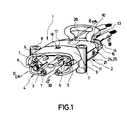
- a connector 1 which has a housing 2 and elongated hermaphrodite contacts 3 inserted therein.
- this connector is shown with a view of the mating face 4. It can also be seen there that the hermaphrodite contacts have the shape of two opposing circular segments in cross section, the plug end 5 facing the plug face 4 being covered by triangular cover surfaces 6. In addition to the free flanks 7 of the plug ends 5, up to the end edge of the mating face 4, elevations 8 in the form of pins or the like are provided which, together with the cover surfaces 6, ensure protection against contact and make it impossible to touch the contacts 3.
- the housing 2 of a connector consists of a frame 9, into which the hermaphrodite contacts 3 are inserted from the side opposite the plug face 4, and of two cover halves 10 and 11, which form the connection ends 12 of the hermaphrodite contacts 3 cover and on the back of which the corresponding halves 14 and 15 of a strain relief clamp 13 are attached.
- the lid halves 10 and 11 are hinged to the frame 9.
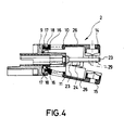
- the hinges comprise a pull tab 16, the free end of which is provided with a locking wedge 17 which engages behind an opening 18 in the frame 9, as can be seen particularly well from the upper half in FIG. 4.
- the hinges include a pressure tab 18 which engages behind an abutment shoulder 20 of the hermaphrodite contacts 3, with which the hermaphrodite contacts 3 are also supported with respect to the frame 9. This can be seen particularly well from FIG. 2.
- the hermaphrodite contacts 3 are axially caught with their contact shoulder 20 between a contact surface of the frame 9 and between the ends of the pressure tabs 19 when the cover halves 10 and 11 are in the closed state shown in FIG. 2.
- the pressure tabs 19 point obliquely forward from the cover halves 10 and 11 in the direction of insertion of the hermaphrodite contacts 3 and are designed to be flexible.
- the free ends of the pressure tabs are adapted to the outer contour of the hermaphrodite contacts and lie on the outer contour of the hermaphrodite contacts 3.
- two lateral webs 21 which extend to the rear are formed on the rear side of the frame 9 facing away from the plug face 4.
- the webs have a vertical section in about the first two thirds and a horizontal section 23 in the last third.
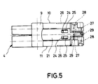
- latching openings 24 are provided which cooperate with corresponding latching wedges 25 arranged laterally on the outer sides of the lid halves when the lid halves are closed (cf. FIG. 5).
- the clamp halves 14 and 15 of the strain relief clamp 13 are arranged on the back of the cover halves 10 and 11, respectively.
- the clamp halves are fastened to the cover half 10 or 11 via a tab 26 which lies in the cover surface of a cover half and extends approximately to the middle of the cover half.
- the tab 26 is formed in that the cover is slotted into the side of the tab 26 up to approximately the center of the cover.
- the clamp halves 14 and 15 are relatively rigid in themselves and have bores 27 and 28 at their ends.
- the holes 27 and 28 lie side by side so that they form the corners of a square.
- the bores 27 have a larger diameter than the bores 28, two bores of the same diameter each lying diagonally opposite one another.
- the clamp halves 14 and 15 are fastened by so-called self-tapping screws which can be inserted through the bores 27 of larger diameter and cut their threads into the edge of the bores 28 of smaller diameter.
- bores 29 are provided which are aligned with the bores 27 and 28 of the cover halves when the cover halves 10 and 11 are attached to the frame 9.
- a frame 9 (see FIG. 6) and two cover halves 10 and 11 (see FIG. 7), as well as two hermaphrodite contacts 3 and two self-tapping screws are required.
- the two cover halves 10 and 11 if necessary at all, are hung with their pull tabs 16 in the openings 18 of the associated frame 9.
- the connector thus prepared then arrives at the customer.
- the customer connects the two hermaphrodite contacts 3 with the ends of the associated connecting cables, which z. B. can be done by squeezing the terminal ends 12.
- the hermaphrodite contacts 3 are then inserted with half-opened cover halves (see FIG. 4 below) in push-through openings of the frame, the elastic pressure tabs 19 being able to deflect upwards and downwards until the hermaphrodite contacts with their contact shoulders 20 after passing the pressure tabs 19 on the frame 9 concerns.
- the hermaphrodite contact must pass a narrow point in the through-opening adapted to the shape of the profile cross section, as a result of which the hermaphrodite contact is automatically aligned in its correct position.
- the pressure tabs 19 then engage behind the contact shoulders 20.
- the cover halves can then simply be pressed together, the lateral locking wedges 25 engaging in the locking openings 24 on the lateral webs of the frame 9, so that the two cover halves 10 and 11 snap together
- the cover surfaces 6 and the elevations 8 do not interfere when plugged together, but they offer effective protection against accidental contact with the contacts.
Abstract
Description
Die Erfindung bezieht sich auf einen Steckverbinder, insbesondere Zwittersteckverbinder, mit einem Gehäuse und in dieses eingesetzten, langgestreckten, ein Anschlußende und ein dem Steckgesicht des Gehäuses zugewandtes Steckende aufweisenden Kontakten, wobei das Gehäuse das Anschlußende der Kontakte übergreift und mit mindestens einer Zugentlastungsschelle für Anschlußkabel versehen ist.The invention relates to a connector, in particular hermaphrodite connector, with a housing and inserted therein, elongated contacts having a connection end and a plug end facing the plug face of the housing, the housing overlapping the connection end of the contacts and provided with at least one strain relief clamp for connection cables is.
Derartige Steckverbinder sind aus der Praxis bekannt als Ladesteckverbinder. Sie dienen zur Übertragung von Hochstrom zwischen Ladestation und Batterie von batteriebetriebenen Fahrzeugen, sowie zwischen Batterie und Motor eines solchen Fahrzeuges.Such connectors are known in practice as charging connectors. They are used to transmit high current between the charging station and battery of battery-operated vehicles, and between the battery and engine of such a vehicle.
Aus der Praxis sind Steckverbinder bekannt, die aus Zwei miteinander verschraubten Gehäusehälften bestehen, wobei zur Montage der Steckverbinder die Kontakte in eine Gehäusehälfte eingelegt werden, wonach dann die andere Gehäusehälfte darübergelegt und mit der ersten Gehäusehälfte verschraubt wird.In practice, connectors are known which consist of two housing halves screwed together, the contacts being inserted into one housing half for assembly of the connectors, after which the other housing half is then placed over it and screwed to the first housing half.
Ferner sind auch Steckverbindergehäuse bekannt, bei denen die Kontakte in Richtung ihrer Längserstreckung eingeschoben werden können, wobei anschließend quer zur Steckrichtung in das Gehäuse eingesetzte Verriegelungsstifte oder -klammern eingesetzt werden müssen, um die Kontakte in Steckrichtung zu verriegeln. Das ist nicht immer ganz einfach, da sich die Kontakte um ihre Längsachse verdrehen können und erst durch die Verriegelungsstifte genau in Position gehalten werden. Außerdem bestehen auch diese Gehäuse aus zwei miteinander verschraubten Gehäusehälften.Furthermore, connector housings are also known in which the contacts can be inserted in the direction of their longitudinal extent, locking pins or clips inserted into the housing transversely to the plugging direction then having to be used in order to lock the contacts in the plugging direction. This is not always easy because the contacts can twist about their longitudinal axis and are only held in position by the locking pins. In addition, these housings also consist of two together screwed housing halves.
Die Montage der oben beschriebenen Steckverbinder erfolgt in zwei Stufen. In der ersten Stufe, der Vormontage müssen zumindest die Gehäusehälften miteinander verschraubt werden, wobei es bei den bekannten Steckverbindern jedoch auch sinnvoll ist, die Kontakte und die Befestigungselemente einzusetzen, damit die Befestigungselemente, die verhältnismäßig klein sind, beim Versand der Steckverbinder nicht verlorengehen. In der zweiten Montagestufe, die beim Kunden, d. h. beim Fahrzeughersteller, stattfindet, müssen die Steckverbinder dann teilweise wieder auseinandergenommen werden, wonach die Kontakte mit den Enden der Anschlußkabel verbunden und wieder in das Gehäuse eingesetzt werden. Das bedeutet, daß bei herkömmlichen Steckverbindern in der ersten und in der zweiten Montagestufe Arbeiten doppelt vorgenommen werden müssen, was die Kosten des Einsatzes solcher Steckverbinder erhöht. Will man diese doppelten Arbeiten vermeiden, erhält der Kunde eine Vielzahl von zum Teil kleinen Bauteilen, von denen er nicht genau weiß, wie sie montiert werden sollen. Auch hierdurch treten Verzögerungen ein, die den Einsatz solcher Steckverbinder verteuern.The assembly of the connectors described above takes place in two stages. In the first stage, the pre-assembly, at least the housing halves have to be screwed together, but it is also useful in the known connectors to use the contacts and the fastening elements so that the fastening elements, which are relatively small, are not lost when the connectors are shipped. In the second assembly stage, which the customer, d. H. at the vehicle manufacturer, the connectors must then be partially taken apart again, after which the contacts are connected to the ends of the connecting cables and inserted back into the housing. This means that with conventional connectors, work has to be carried out twice in the first and in the second assembly stage, which increases the cost of using such connectors. If you want to avoid this duplication of work, the customer receives a large number of small components, some of which he does not know exactly how to assemble. This also results in delays that make the use of such connectors more expensive.
Es ist daher Aufgabe der vorliegenden Erfindung, einen Steckverbinder der eingangs genannten Art so zu verbessern, daß sowohl die Vormontage als auch die Endmontage der Steckverbinder vereinfacht wird, wobei insbesondere Doppeltarbeiten bei Vor- und Endmotage weitestgehend vermieden werden soll.It is therefore an object of the present invention to improve a plug connector of the type mentioned at the outset in such a way that both the preassembly and the final assembly of the plug connectors are simplified, in particular duplication of work in the case of preassembly and final assembly to be largely avoided.
Diese Aufgabe wird erfindungsgemäß dadurch gelöst, daß an den Kontakten zwischen deren Steckende und deren Anschlußende mindestens eine Anschlagschulter ausgebildet ist, daß das Gehäuse quer zur Steckrichtung geteilt ist und einen das Steckgesicht aufweisenden Rahmen, in dem die Kontakte von der dem Steckgesicht abgewandten Seite her mit ihrem Steckende bis zum Anliegen der Anschlagschulter an dem Rahmen eingeschoben sind, und zwei an der dem Steckgesicht abgewandten Seite des Rahmens über je ein Deckelscharnier angelenkte und verschließbare Deckelhälften aufweist, die in geschlossenem Zustand die Anschlußenden der Kontakte überdecken, und daß die Deckelscharniere je mindestens eine Zuglasche und eine Drucklasche aufweisen, die an der dem Rahmen zugewandten Seite des Deckels befestigt sind, wobei die Zuglasche an der dem Steckgesicht abgewandten Seite des Rahmens gehalten ist, während die Drucklasche der dem Rahmen abgewandte Seite der Anlageschulter der Kontakte hintergreifen.This object is achieved in that at least one stop shoulder is formed on the contacts between their plug end and their connection end that the housing is divided transversely to the direction of insertion and a frame with the mating face, in which the contacts are inserted with their plug end from the side facing away from the mating face until the abutment shoulder rests against the frame, and two cover halves articulated and closable on the side of the frame facing away from the mating face via a lid hinge each has, which cover the connection ends of the contacts in the closed state, and that the cover hinges each have at least one pull tab and one pressure tab which are attached to the side of the cover facing the frame, the pull tab being held on the side of the frame facing away from the mating face , while the pressure tab on the side of the contact shoulder facing away from the frame engages behind.
Diese Lösung verringert auf überraschende Weise den Montageaufwand und zugleich auch die Anzahl der notwendigen Bauteile eines Steckverbinders, da den Bauteilen Mehrfachfunktionen zugewiesen werden. So dienen z. B. die beiden Deckelhälften nicht nur zum Abdecken des Anschlußendes der Kontakte, sondern auch zur Lagefixierung der Kontakte in dem Gehäuse, in dem die Anlageschultern der Kontakte durch die Drucklasche der Scharniere und durch den Rahmen des Gehäuses in axialer Richtung gehalten sind. Bei der Vormontage des Steckverbinders Könnenen die Deckelhälften mit den Zuglaschen an dem Rahmen vorfixiert werden. Der Kunde schließt lediglich noch die Kontakte an die Kabelenden an, z. B. durch Anquetschen, und schiebt die Kontakte von hinten her rastend in den Rahmen des Gehäuses ein. Dann werden die Deckelhälften zusammengedrückt und geschlossen, wonach dann lediglich noch die Zugentlastungsschellen festzuziehen sind. Der Kunde muß also nicht das Gehäuse zunächst wieder auseinandernehmen, um die Kontakte einzusetzen, darüber hinaus erübrigt sich auch das Vorsehen zusätzlicher Verriegelungsstifte oder -klammern, da die Verriegelung über Drucklaschen an den Gehäusedeckeln erfolgt.This solution surprisingly reduces the assembly effort and at the same time the number of necessary components of a connector, since the components are assigned multiple functions. So serve z. B. the two cover halves not only to cover the connection end of the contacts, but also to fix the contacts in the housing in which the contact shoulders of the contacts are held in the axial direction by the pressure plate of the hinges and by the frame of the housing. When pre-assembling the connector, the cover halves can be pre-fixed to the frame with the pull tabs. The customer simply connects the contacts to the cable ends, e.g. B. by crimping, and pushes the contacts from behind into the frame of the housing. Then the lid halves are pressed together and closed, after which only the strain relief clamps are then tightened. The customer does not have to take the housing apart again in order to insert the contacts, and there is also no need to provide additional ones Locking pins or clamps because the locking is done via pressure tabs on the housing covers.
Sowohl für die Herstellung als auch für die Montage günstig ist es, wenn die Zuglasche der Deckelscharniere in einem Rasthaken endet, der den Rand einer Ausnehmung in dem Rahmen hintergreift. Das Gehäuse kann dann insgesamt dreiteilig ausgebildet sein, wobei die beiden Deckelhälften identisch sein können, so daß nur zwei Spritzgußwerkzeuge erforderlich sind, wenn man das Gehäuse, wie üblich, durch Spritzgießen herstellen.It is favorable both for the manufacture and for the assembly if the pull tab of the cover hinges ends in a latching hook which engages behind the edge of a recess in the frame. The housing can then be constructed in three parts, the two cover halves being identical, so that only two injection molding tools are required if the housing is produced by injection molding, as is customary.
Es ist außerdem günstig, wenn das freie Ende der Drucklaschen der Umfangsform der Kontakte angepaßt ist und im geschlossenen Zustand der Deckelhälften auf den Kontakten aufliegt. Das hat den Vorteil, daß die Drucklaschen die Genäusehälften mit den Zuglaschen in die Rastausnehmungen in den Rahmen eindrücken, so daß sich die Scharniere verspannen.It is also advantageous if the free end of the pressure tabs is adapted to the circumferential shape of the contacts and rests on the contacts in the closed state of the cover halves. This has the advantage that the pressure straps press the neck halves with the pull straps into the locking recesses in the frame, so that the hinges are braced.
Hierbei ist es besonders günstig, wenn die Drucklaschen in Steckrichtung schräg zu den Kontakten weisen und elastisch biegbar ausgebildt sind, so daß sowohl eine Lagefixierung der Kontakte zwischen den Deckelhälften und dem Rahmen stattfindet, als auch die Scharniere elastisch verspannt werden.It is particularly advantageous if the pressure tabs point obliquely to the contacts in the direction of insertion and are designed to be elastically bendable, so that the contacts between the cover halves and the frame are fixed in position, and the hinges are elastically tensioned.
Obgleich es auch denkbar wäre, daß die beiden Deckelhälften durch Rasten unmittelbar miteinander verbunden werden, hat es sich, insbesondere aus Stabilitätsgründen als vorteilhaft herausgestellt, wenn der Rahmen zwei sich seitlich gegenüberliegende und von seiner dem Steckgesicht abgewandten Rückseite nach rückwärts ertreckende Stege aufweist, an denen zur Seite weisende Rasten angebracht sind, die im geschlossenen Zustand der Deckelhälften mit ebenfalls zur Seite weisenden Gegenrasten an den Deckelhälften zusammenwirken.Although it would also be conceivable for the two halves of the cover to be connected directly to one another by latching, it has turned out to be advantageous, in particular for reasons of stability, if the frame has two laterally opposite webs which extend backwards from its mating face and on which back to the side facing detents are attached, which in the closed state of the lid halves also to the side interacting counter detents on the cover halves.
Bevorzugt wird auch, wenn die Stege die Deckelhälften seitlich einrahmen, da dann seitlich auftretende Kräfte, die z. B. beim Herunterfallen eines Steckverbinders auftreten können, nicht unmittelbar an den Deckelhälften angreifen.It is also preferred if the webs laterally frame the lid halves, since then lateral forces which, for. B. can occur when a connector falls down, do not attack directly on the cover halves.
Wenn die Rasten der Stege als Rastausnehmungen ausgebildet sind, während die Gegenrasten als Rastkeile ausgebildet sind, die in die Rastausnehmungen eingreifen, läßt sich von außen immer erkennnen, ob die Deckelhälften richtig eingerastet sind oder nicht.If the catches of the webs are designed as catch recesses, while the counter catches are designed as catch wedges which engage in the catch recesses, it can always be seen from the outside whether the cover halves are correctly engaged or not.
Ganz besonders bevorzugt wird, wenn die Zugentlastungsschelle für die Anschlußkabel aus zwei Hälften bestehen, wobei je eine Hälfte an der dem Rahmen abgewandten Rückseite einer Deckelhälfte über eine elastisch biegbare Laschen angelenkt ist. Auf diese Weise werden die beiden Deckelhälften im geschlossenen Zustand des Steckverbinders auch noch durch die Zugentlastungsschelle gehalten, deren Hälften üblicherweise durch Schrauben zusammengehalten werden. Der Rastverbindung zwischen den Deckelhälften und den seitlichen Stegen kommt damit im wesentlichen nur eine Montagehilfe zu, die im Gebrauchszustand des Steckverbinders nicht mehr unbedingt benötigt wird.It is very particularly preferred if the strain relief clamp for the connecting cable consists of two halves, one half being articulated on the back of a cover half facing away from the frame via an elastically bendable tabs. In this way, the two cover halves are also held in the closed state of the connector by the strain relief clamp, the halves of which are usually held together by screws. The latching connection between the cover halves and the lateral webs is therefore essentially only an assembly aid, which is no longer absolutely necessary when the connector is in use.
Besonders günstig ist es, wenn die biegbare Lasche als durch Schlitze seitlich begrenzter Streifen der Deckelfläche ausgebildet ist, der sich von etwa der Mitte der Deckelfläche aus bis zur Rückseite einer Deckelhälfte erstreckt. Durch diese verhältnismäßig lange Lasche können sich die Hälften der Zugentlastungsschelle sowohl verhältnismäßig dicken als auch verhältnismäßig dünnen Kabeln anpassen.It is particularly expedient if the bendable tab is formed as a strip of the cover surface which is laterally delimited by slots and which extends from approximately the center of the cover surface to the rear of a cover half. This relatively long tab enables the halves of the strain relief clamp to adapt to both relatively thick and relatively thin cables.
Um bei der Montage der Zugentlastungsschellen den Steckverbinder nicht von einer Seite auf die andere Seite drehen zu müssen, und um dennoch identische Gehäusehälften verwenden zu können, kann jede Hälfte einer Zugentlastungsschelle jeweils mindestens vier Bohrungen für Befestigungsschrauben aufweisen, die mit den vier bohrungen der anderen Schellenhälfte fluchten, wobei jeweils zwei sich diagonal gegenüberliegende Bohrungen einen geringeren Durchmesser aufweisen als die anderen zwei Bohrungen. Die Zugentlastungsschellen können auf diese Weise mit selbstschneidenden Schrauben verbunden werden, deren Gewindeteile in die Bohrungen geringeren Durchmessers einschneidet. Da insgesamt vier Bohrungen vorgesehen sind, besitzt jede Schellenhälfte zwei große Bohrungen, die mit zwei kleinen Bohrungen der anderen Schellenhälfte fluchten. Auf diese Weise können die Befestigungsschrauben stets von einer Seite her in die Zugentlastungsschelle eingeschraubt werden, was wiederum eine Montagevereinfachung bedeutet.In order not to have to turn the connector from one side to the other when installing the strain relief clamps, and to still be able to use identical housing halves, each half of a strain relief clamp can have at least four holes for fastening screws each, which are connected to the four holes in the other half of the clamp are aligned, with two diagonally opposite holes each having a smaller diameter than the other two holes. The strain relief clamps can be connected in this way with self-tapping screws, the threaded parts of which cut into the holes of smaller diameter. Since a total of four holes are provided, each clamp half has two large holes that are aligned with two small holes in the other half of the clamp. In this way, the fastening screws can always be screwed into the strain relief clamp from one side, which in turn simplifies assembly.
Aus Stabilitätsgründen ist es ferner günstig, wenn die seitlichen Stege des Rahmens sich bis zwischen die Hälften der Zugentlastungsschelle erstrecken und jeweils zwei Bohrungen aufweisen, die mit den Bohrungen der Schellenhälften fluchten. Beim Zusammenklemmen der Schellenhälften werden damit die Deckel zusätzlich noch an den seitlichen Stegen des Rahmens befestigt, so daß auch das Scharnier für die Deckelhälften entlastet wird. Beim Montieren des so ausgerüsteten Steckverbinders müssen lediglich zwei Schrauben eingeschraubt werden, die zudem noch von der gleichen Seite eingeschraubt werden, um den kompletten Steckverbinder einschließlich Zugentlastung in den betriebsfertigen Zustand zu bringen.
Wenn die Kontakte als kreuzweise steckbare, im Querschnitt etwa die Form zweier sich über Eck gegenüberliegender Kreisscheibensegmente aufweisende Zwitterkontakte ausgebildet sind, wenn am frei endenden Rand des Steckgesichts des Rahmens dreiecksförmige Deckflächen ausgebildet sind, die die Stirnseiten der Steckenden der in den Steckverbinder eingesetzten Zwitterkontakte überdecken, und wenn an der Grundfläche des Steckgesichts, aus der die Steckenden der Kontakte heraustreten, bis zum frei endenden Rand des Steckgesichts reichenden Erhebungen ausgebildet sind, die vor den offenen Flanken der Steckenden der Zwitterkontakte als Berührungsschutz angeordnet sind, ist es unmöglich, bei nicht zusammengesteckten Steckverbindern mit Fingern an stromführende Teile im Steckgesicht des Steckverbinders zu gelangen.For reasons of stability, it is also advantageous if the lateral webs of the frame extend as far as between the halves of the strain relief clamp and each have two bores which are aligned with the bores of the clamp halves. When the clamp halves are clamped together, the covers are additionally fastened to the lateral webs of the frame, so that the hinge for the cover halves is also relieved. When assembling the connector equipped in this way, only two screws have to be screwed in, which are also screwed in from the same side, in order to bring the complete connector including strain relief into the operational state.
If the contacts are pluggable crosswise, in cross-section approximately the shape of two opposite one another Hermaphrodite contacts having circular disk segments are formed if triangular cover surfaces are formed on the free-ending edge of the mating face of the frame, which cover the end faces of the mating ends of the hermaphrodite contacts inserted in the connector, and if on the base surface of the mating face from which the mating ends of the contacts emerge until are formed to the free-ended edge of the mating face elevations, which are arranged in front of the open flanks of the mating contacts as contact protection, it is impossible to get fingers at live parts in the mating face of the connector when the connectors are not plugged together.
Im folgenden wird ein Ausührungsbeispiel der Erfindung anhand einer Zeichnung näher erläutert. Es zeigen:
-
Figur 1 einen erfindungsgemäßen Steckverbinder in einer perspektivischen Ansicht mit Blick auf das Steckgesicht, -
Figur 2 zwei Steckverbinder gemäßFigur 1 im gesteckten Zustand, geschnitten entlang der Linie II-II ausFigur 1, -
Figur 3 eine Draufsicht auf einen Steckverbinder gemäßFigur 1, teilweise geschnitten, entlang der Linie III-III, -
Figur 4 eine Schnittansicht durch den Steckverbinder gemäßFigur 3, entlang der Linie IV-IV, mit abgeklappter unterer Deckelhälfte, - Figur 5 eine Seitenansicht des Steckverbindergehäuses aus
Figur 3, mit zusammengeklappten Deckelhälften und -
Figur 6 eine Draufsicht auf den Gehäuserahmen des zuvor beschriebenen Steckverbinders und -
Figur 7 eine Draufsicht auf eine zugehörige Deckelhälfte.
- 1 shows a connector according to the invention in a perspective view with a view of the mating face,
- FIG. 2 shows two plug connectors according to FIG. 1 in the inserted state, cut along the line II-II from FIG. 1,
- FIG. 3 shows a top view of a connector according to FIG. 1, partly in section, along the line III-III,
- FIG. 4 shows a sectional view through the plug connector according to FIG. 3, along the line IV-IV, with the lower half of the cover folded down,
- Figure 5 is a side view of the connector housing of Figure 3, with the lid halves and folded
- Figure 6 is a plan view of the housing frame of the connector described above and
- Figure 7 is a plan view of an associated lid half.
In der Zeichnung ist ein Steckverbinder 1 dargestellt, der ein Gehäuse 2 und in dieses eingesetzte, langgestreckte Zwitterkontakte 3 aufweist.In the drawing, a
In Figur 1 ist dieser Steckverbinder mit Blick auf das Steckgesicht 4 dargestellt. Dort ist auch zu erkennen, daß die Zwitterkontakte im Querschnitt die Form zweier sich gegenüberliegender Kreissegmente aufweisen, wobei das dem Steckgesicht 4 zugewandte Steckende 5 durch dreieckigförmige Deckflächen 6 abgedeckt ist. Neben den freien Flanken 7 der Steckenden 5 sind bis zur Abschlußkante des Steckgesichts 4 reichende Erhebungen 8 in Form von Stiften oder dergleichen vorgesehen, die, zusammen mit den Deckflächen 6 einen Berührungsschutz gewährleisten und ein Anfassen der Kontakte 3 unmöglich macht.In Figure 1, this connector is shown with a view of the
Wie besser aus den üblichen Figuren ersichtlich ist, besteht das Gehäuse 2 eines Steckverbinders aus einem Rahmen 9, in welchen die Zwitterkontakte 3 von der dem Steckgesicht 4 gegenüberliegenden Seite her eingeschoben sind, und aus zwei Deckelhälften 10 und 11, die die Anschlußenden 12 der Zwitterkontakte 3 überdecken und an deren Rückseite die miteinander korrespondierenden Hälften 14 und 15 einer Zugentlastungsschelle 13 befestigt sind.As can be seen better from the usual figures, the
Die Deckelhälften 10 und 11 sind mittels Scharniere an dem Rahmen 9 angelenkt. Die Scharniere umfassen eine Zuglasche 16, deren freies Ende mit einem Rastkeil 17 versehen ist, der von innen her einen Durchbruch 18 im Rahmen 9 hintergreift, wie besonders gut aus der oberen Hälfte in Figur 4 ersichtlich ist.The lid halves 10 and 11 are hinged to the
Ferner umfassen die Scharniere eine Drucklasche 18, die eine Anlageschulter 20 der Zwitterkontakte 3 hintergreifen, mit der sich die Zwitterkontakte 3 auch gegenüber dem Rahmen 9 abstützen. Dies ist besonders gut aus Figur 2 ersichtlich. Die Zwitterkontakte 3 sind mit ihrer Anlageschulter 20 zwischen einer Anlagefläche des Rahmens 9 und zwischen den Enden der Drucklaschen 19 axial gefangen, wenn die Deckelhälften 10 und 11 in dem in Figur 2 dargestellten, geschlossenen Zustand sind. Die Drucklaschen 19 weisen von den Deckelhälften 10 und 11 schräg nach vorn in Steckrichtung der Zwitterkontakte 3 und sind biegeelastisch ausgebildet. Die freien Enden der Drucklaschen sind der Außenkontur der Zwitterkontakte angepaßt und liegen auf der Außenkontur der Zwitterkontakte 3 auf.Furthermore, the hinges include a
Wie besonders gut aus den Figuren 5 und 6 ersichtlich ist, sind an der dem Steckgesicht 4 abgewandten Rückseite des Rahmens 9 zwei seitliche, sich nach hinten erstreckende Stege 21 ausgebildet. Die Stege weisen in etwa den ersten zwei Dritteln einen vertikalen Abschnitt und im letzten Drittel einen horizontalen Abschnitt 23 auf. In den vertikalen Abschnitten 23 sind Rastdurchbrüche 24 vorgesehen, die mit entsprechenden, an den Außenseiten der Deckelhälften seitlich angeordneten Rastkeilen 25 zusammenwirken, wenn die Deckelhälften geschlossen (vergl. Fig. 5).As can be seen particularly well from FIGS. 5 and 6, two
Wie besonders gut aus Figur 7 hervorgeht, sind die Schellenhälften 14 bzw. 15 der Zugentlastungsschelle 13 an der Rückseite der Deckelhälften 10 bzw. 11 angeordnet. Die Schellenhälften sind über eine Lasche 26, die in der Deckfläche einer Deckelhälfte liegt, und sich bis ungefähr in die Mitte der Deckelhälfte erstreckt an der Deckelhälfte 10 bzw. 11 befestigt. Die Lasche 26 ist dadurch gebildet, daß der Deckel bis etwa zur Deckelmitte hin seitlich der Lasche 26 eingeschlitzt ist.As can be seen particularly well from FIG. 7, the clamp halves 14 and 15 of the
Die Schellenhälften 14 und 15 sind in sich relativ starr und weisen an ihren Enden Bohrungen 27 und 28 auf. Die Bohrungen 27 und 28 liegen nebeneinander, so daß sie die Ecken eines Vierecks bilden. Die Bohrungen 27 weisen einen größeren Durchmesser auf als die Bohrungen 28, wobei sich jeweils zwei Bohrungen gleichen Durchmessers diagonal gegenüberliegen. Befestigt werden die Schellenhälften 14 und 15 durch sogenannte selbstschneidende Schrauben, die sich durch die Bohrungen 27 größeren Durchmessers hindurchstecken lassen, und deren Gewinde in den Rand der Bohrungen 28 kleineren Durchmessers einschneiden.The clamp halves 14 and 15 are relatively rigid in themselves and have
In dem horizontalen Abschnitt 23 der Stege 21 des Rahmens 9 sind Bohrungen 29 vorgesehen, die mit den Bohrungen 27 und 28 der Deckelhälften fluchten, wenn die Deckelhälften 10 und 11 an dem Rahmen 9 angebracht sind.In the
Im folgenden wird die Wirkungs- und Funktionsweise des oben beschriebenen Steckverbinders 1 anhand der Vormontage, der Endmontage und der Benutzung näher erläutert.The operation and functioning of the
Benötigt werden ein Rahmen 9 (vergl. Fig. 6) und zwei Deckelhälften 10 und 11 (vergl. Fig. 7), sowie zwei Zwitterkontakte 3, und zwei selbstschneidende Schrauben. In der Vormontage, die noch beim Hersteller stattfindet, werden, sofern überhaupt erforderlich, die beiden Deckelhälften 10 und 11 mit ihren Zuglaschen 16 in die Durchbrüche 18 des zugehörigen Rahmens 9 eingehängt.A frame 9 (see FIG. 6) and two
Der so vorbereitete Steckverbinder gelangt dann zu dem Kunden. Der Kunde verbindet die beiden Zwitterkontakte 3 mit den Enden der zugehörigen Anschlußkabel, was z. B. durch Verquetschen der Anschlußenden 12 geschehen kann. Die Zwitterkontakte 3 werden dann bei halbgeöffneten Deckelhälften (vergl. Fig. 4 unten) in Durchstecköffnungen des Rahmens eingeschoben, wobei die elastischen Drucklaschen 19 nach oben und nach unten ausweichen können, bis die Zwitterkontakte mit ihren Anlageschultern 20 nach Passieren der Drucklaschen 19 an dem Rahmen 9 anliegen. Dabei muß der Zwitterkontakt eine dem -förmigen Profilquerschnitt angepaßte Engstelle in der Durchstecköffnung passieren, wodurch der zwitterkontakt automatisch in seiner richtigen Lage ausgerichtet wird. Die Drucklaschen 19 hintergreifen dann die Anlageschultern 20. Die Deckelhälften können dann einfach zusammengedrückt werden, wobei die seitlichen Rastkeile 25 in die Rastdurchbrüche 24 an den seitlichen Stegen des Rahmens 9 eingreifen, so daß die beiden Deckelhälften 10 und 11 zuschnappen.The connector thus prepared then arrives at the customer. The customer connects the two
Dann werden in die größeren Bohrungen 27 einer Schellenhälfte 14 die selbstschneidenden Schrauben eingesteckt und eingedreht, bis die Zugeentlastungsschellen die Anschlußkabel festklemmen. Dabei spielt es keine Rolle, welche Seite des Steckverbinders 1 oben liegt, da auf beiden Seiten jeweils größere Bohrungen 27 vorgesehen sind. Mit diesen wenigen Handgriffen ist der Steckverbinder bereits gebrauchsfertig und kann mit einem gleichkodierten Steckverbinder zusammengesteckt werden (vergl. Fig. 2).Then the self-tapping screws are inserted and screwed into the larger bores 27 of a
Die Deckflächen 6 und die Erhebungen 8 stören beim Zusammenstecken nicht, sie bieten jedoch einen wirksamen Berührungsschutz gegen unbeabsichtigtes Berühren der Kontakte.The cover surfaces 6 and the elevations 8 do not interfere when plugged together, but they offer effective protection against accidental contact with the contacts.
Claims (12)
dadurch gekennzeichnet,
daß an den Kontakten (3) zwischen deren Steckende (5) und deren Anschlußende (12) mindestens eine Anschlagschulter (20) ausgebildet ist, daß das Gehäuse (2) quer zur Steckrichtung geteilt ist und einen das Steckgesicht (4) aufweisenden Rahmen (9), in dem die Kontakte (3) von der dem Steckgesicht (4) abgewandten Seite her mit ihrem Steckende (5) bis zum Anliegen der Anschlagschulter (20) an den Rahmen (9) eingeschoben sind, und zwei an der dem Steckgesicht (4) abgewandten Seite des Rahmens (9) über je ein Deckelscharnier angelenkt und verschließbare Deckelhälften (10, 11) aufweist, die im geschlossenen Zustand die Anschlußenden (12) der Kontakte (3) überdecken, und daß die Deckelscharniere je mindestens eine Zuglasche (16) und eine Drucklasche (19) aufweisen, die an der dem Rahmen (9) zugewandten Seite des Deckels befestigt sind, wobei die Zuglasche (16) an der dem Steckgesicht (4) abgewandten Seite des Rahmens (9) gehalten ist, während die Drucklaschen (19) die dem Rahmen (9) abgewandte Seite der Anschlagschulter (20) der Kontakte (3) hintergreifen.Plug connector, in particular hermaphrodite plug connector, with a housing (2), and in this, elongated contacts, which have a connection end and a plug end facing the plug face of the housing, the housing engaging over the connection end of the contacts and being provided with at least one strain relief clamp for the connection cable ,
characterized by
that at least one stop shoulder (20) is formed on the contacts (3) between their plug end (5) and their connection end (12), that the housing (2) is divided transversely to the plugging direction and a frame (9) having the plug face (4) ), in which the contacts (3) are inserted from the side facing away from the plug face (4) with their plug end (5) until the stop shoulder (20) bears against the frame (9), and two on the plug face (4 ) opposite side of the frame (9) articulated via a lid hinge each and has closable lid halves (10, 11) which cover the connecting ends (12) of the contacts (3) in the closed state, and that the lid hinges each have at least one pull tab (16) and have a pressure flap (19) which are fastened to the side of the cover facing the frame (9), the pull flap (16) being held on the side of the frame (9) facing away from the plug face (4), while the pressure flaps ( 19) which the frame (9 ) reach behind the opposite side of the stop shoulder (20) of the contacts (3).
Applications Claiming Priority (2)
| Application Number | Priority Date | Filing Date | Title |
|---|---|---|---|
| DE9004383U DE9004383U1 (en) | 1990-04-17 | 1990-04-17 | |
| DE9004383U | 1990-04-17 |
Publications (2)
| Publication Number | Publication Date |
|---|---|
| EP0452555A1 true EP0452555A1 (en) | 1991-10-23 |
| EP0452555B1 EP0452555B1 (en) | 1995-03-08 |
Family
ID=6852974
Family Applications (1)
| Application Number | Title | Priority Date | Filing Date |
|---|---|---|---|
| EP90124141A Expired - Lifetime EP0452555B1 (en) | 1990-04-17 | 1990-12-13 | Connector, especially hermaphrodite connector |
Country Status (3)
| Country | Link |
|---|---|
| EP (1) | EP0452555B1 (en) |
| BG (1) | BG60080A3 (en) |
| DE (2) | DE9004383U1 (en) |
Cited By (7)
| Publication number | Priority date | Publication date | Assignee | Title |
|---|---|---|---|---|
| WO1993023897A1 (en) * | 1992-05-21 | 1993-11-25 | Plantronics, Inc. | Quick disconnect wiring connector |
| WO1998000887A1 (en) * | 1996-07-01 | 1998-01-08 | Siemens Aktiengesellschaft | Plug-in connector with closable cover piece and method of connecting a lead wire to such a plug-in connector |
| US5890922A (en) * | 1996-09-11 | 1999-04-06 | The Whitaker Corporation | Electrical connector |
| EP0932224A1 (en) * | 1998-01-27 | 1999-07-28 | Wilfried Pöllet | Démontable multi-pole electrical connector |
| GB2349516A (en) * | 1999-03-17 | 2000-11-01 | Whittaker Corp The | Contact-retaining shroud for electrical connector |
| CN109524843A (en) * | 2019-01-07 | 2019-03-26 | 东莞市联纲光电科技有限公司 | Quick connector |
| CN113451822A (en) * | 2021-07-13 | 2021-09-28 | 四川华丰科技股份有限公司 | Integral high-current connector |
Families Citing this family (1)
| Publication number | Priority date | Publication date | Assignee | Title |
|---|---|---|---|---|
| DE102020134071A1 (en) | 2020-12-17 | 2022-06-23 | Bayerische Motoren Werke Aktiengesellschaft | Expansion module for a vehicle, system with an expansion module, and vehicle with a mount for an expansion module |
Citations (2)
| Publication number | Priority date | Publication date | Assignee | Title |
|---|---|---|---|---|
| US3794957A (en) * | 1973-01-22 | 1974-02-26 | Anderson Power Products | Plural-poled, genderless electrical connector |
| FR2337951A1 (en) * | 1976-01-07 | 1977-08-05 | Amp Inc | HERMAPHRODITE ELECTRICAL CONNECTOR |
-
1990
- 1990-04-17 DE DE9004383U patent/DE9004383U1/de not_active Expired - Lifetime
- 1990-12-13 DE DE59008662T patent/DE59008662D1/en not_active Expired - Fee Related
- 1990-12-13 EP EP90124141A patent/EP0452555B1/en not_active Expired - Lifetime
-
1991
- 1991-04-15 BG BG94260A patent/BG60080A3/en unknown
Patent Citations (2)
| Publication number | Priority date | Publication date | Assignee | Title |
|---|---|---|---|---|
| US3794957A (en) * | 1973-01-22 | 1974-02-26 | Anderson Power Products | Plural-poled, genderless electrical connector |
| FR2337951A1 (en) * | 1976-01-07 | 1977-08-05 | Amp Inc | HERMAPHRODITE ELECTRICAL CONNECTOR |
Non-Patent Citations (1)
| Title |
|---|
| Elektrische Energie Technik EET, vol. 34, no. 6, Dezember 1989, Heidelberg Seite 83 "Huckepack-Stecker" * |
Cited By (9)
| Publication number | Priority date | Publication date | Assignee | Title |
|---|---|---|---|---|
| WO1993023897A1 (en) * | 1992-05-21 | 1993-11-25 | Plantronics, Inc. | Quick disconnect wiring connector |
| AU665103B2 (en) * | 1992-05-21 | 1995-12-14 | Plantronics, Inc. | Quick disconnect wiring connector |
| WO1998000887A1 (en) * | 1996-07-01 | 1998-01-08 | Siemens Aktiengesellschaft | Plug-in connector with closable cover piece and method of connecting a lead wire to such a plug-in connector |
| US5890922A (en) * | 1996-09-11 | 1999-04-06 | The Whitaker Corporation | Electrical connector |
| EP0932224A1 (en) * | 1998-01-27 | 1999-07-28 | Wilfried Pöllet | Démontable multi-pole electrical connector |
| GB2349516A (en) * | 1999-03-17 | 2000-11-01 | Whittaker Corp The | Contact-retaining shroud for electrical connector |
| GB2349516B (en) * | 1999-03-17 | 2003-02-12 | Whittaker Corp The | Shroud for electrical connector |
| CN109524843A (en) * | 2019-01-07 | 2019-03-26 | 东莞市联纲光电科技有限公司 | Quick connector |
| CN113451822A (en) * | 2021-07-13 | 2021-09-28 | 四川华丰科技股份有限公司 | Integral high-current connector |
Also Published As
| Publication number | Publication date |
|---|---|
| DE59008662D1 (en) | 1995-04-13 |
| EP0452555B1 (en) | 1995-03-08 |
| BG60080A3 (en) | 1993-09-15 |
| DE9004383U1 (en) | 1991-08-29 |
Similar Documents
| Publication | Publication Date | Title |
|---|---|---|
| DE3903839C2 (en) | ||
| EP1842266B1 (en) | Electric connector | |
| EP3734768B1 (en) | Electrical plug connector and electrical connector formed therewith | |
| EP0132535A2 (en) | Interconnection system for electrical sockets | |
| EP2475057B2 (en) | Cable holding device | |
| WO2018192616A1 (en) | Retaining frame for a plug connector, and equipping method | |
| DE202017100907U1 (en) | clamp | |
| EP1362393A1 (en) | Plug connector having a housing and a clamping insert | |
| EP0452555B1 (en) | Connector, especially hermaphrodite connector | |
| DE102019135726A1 (en) | Holding frame for a connector | |
| DE102017109899A1 (en) | Electrical connector | |
| DE102019104559A1 (en) | Holding frame for a connector | |
| DE3643087A1 (en) | QUICK COUPLING CLAMP FOR THE TERMINAL POLE OF AN ELECTRICAL DEVICE | |
| DE2855685A1 (en) | ELECTRIC CONNECTOR WITH PANELED FRONT PANEL | |
| DE3522797A1 (en) | Electrical multiple plug device | |
| EP3895254B1 (en) | Plug connector part for contacting in multiple spatial directions | |
| EP3734771B1 (en) | Set of an electrical connector and a functional element | |
| EP4241340A1 (en) | Connector assembly | |
| EP0692846A2 (en) | Lockable connector | |
| EP0757409A1 (en) | Electrical connector | |
| EP1129461B1 (en) | Relay with a coupling element | |
| DE2734333A1 (en) | CONNECTING HOUSING | |
| DE102011002794A1 (en) | Connector, mating connector and connector assembly with clamping surfaces and fixing means | |
| DE4018267C2 (en) | ||
| DE3717017C2 (en) | Plug housing for an electrical connector |
Legal Events
| Date | Code | Title | Description |
|---|---|---|---|
| PUAI | Public reference made under article 153(3) epc to a published international application that has entered the european phase |
Free format text: ORIGINAL CODE: 0009012 |
|
| 17P | Request for examination filed |
Effective date: 19910411 |
|
| AK | Designated contracting states |
Kind code of ref document: A1 Designated state(s): DE FR GB IT SE |
|
| ITCL | It: translation for ep claims filed |
Representative=s name: GIUGNI S.R.L. |
|
| EL | Fr: translation of claims filed | ||
| RAP1 | Party data changed (applicant data changed or rights of an application transferred) |
Owner name: REMA-LIPPRANDT GMBH & CO. KG Owner name: SCHALTBAU AKTIENGESELLSCHAFT |
|
| 17Q | First examination report despatched |
Effective date: 19940222 |
|
| GRAA | (expected) grant |
Free format text: ORIGINAL CODE: 0009210 |
|
| AK | Designated contracting states |
Kind code of ref document: B1 Designated state(s): DE FR GB IT SE |
|
| ET | Fr: translation filed | ||
| REF | Corresponds to: |
Ref document number: 59008662 Country of ref document: DE Date of ref document: 19950413 |
|
| GBT | Gb: translation of ep patent filed (gb section 77(6)(a)/1977) |
Effective date: 19950322 |
|
| ITF | It: translation for a ep patent filed |
Owner name: PROPRIA PROTEZIONE PROPR. IND. |
|
| PLBE | No opposition filed within time limit |
Free format text: ORIGINAL CODE: 0009261 |
|
| STAA | Information on the status of an ep patent application or granted ep patent |
Free format text: STATUS: NO OPPOSITION FILED WITHIN TIME LIMIT |
|
| 26N | No opposition filed | ||
| PGFP | Annual fee paid to national office [announced via postgrant information from national office to epo] |
Ref country code: GB Payment date: 19971121 Year of fee payment: 8 |
|
| PGFP | Annual fee paid to national office [announced via postgrant information from national office to epo] |
Ref country code: FR Payment date: 19971215 Year of fee payment: 8 |
|
| PGFP | Annual fee paid to national office [announced via postgrant information from national office to epo] |
Ref country code: SE Payment date: 19971219 Year of fee payment: 8 |
|
| PG25 | Lapsed in a contracting state [announced via postgrant information from national office to epo] |
Ref country code: GB Free format text: LAPSE BECAUSE OF NON-PAYMENT OF DUE FEES Effective date: 19981213 |
|
| PG25 | Lapsed in a contracting state [announced via postgrant information from national office to epo] |
Ref country code: SE Free format text: LAPSE BECAUSE OF NON-PAYMENT OF DUE FEES Effective date: 19981214 |
|
| PGFP | Annual fee paid to national office [announced via postgrant information from national office to epo] |
Ref country code: DE Payment date: 19990127 Year of fee payment: 9 |
|
| GBPC | Gb: european patent ceased through non-payment of renewal fee |
Effective date: 19981213 |
|
| PG25 | Lapsed in a contracting state [announced via postgrant information from national office to epo] |
Ref country code: FR Free format text: LAPSE BECAUSE OF NON-PAYMENT OF DUE FEES Effective date: 19990831 |
|
| REG | Reference to a national code |
Ref country code: FR Ref legal event code: ST |
|
| PG25 | Lapsed in a contracting state [announced via postgrant information from national office to epo] |
Ref country code: DE Free format text: LAPSE BECAUSE OF NON-PAYMENT OF DUE FEES Effective date: 20001003 |
|
| PG25 | Lapsed in a contracting state [announced via postgrant information from national office to epo] |
Ref country code: IT Free format text: LAPSE BECAUSE OF NON-PAYMENT OF DUE FEES Effective date: 20051213 |