EP0451630A1 - Buffer with a hydraulic damper - Google Patents
Buffer with a hydraulic damper Download PDFInfo
- Publication number
- EP0451630A1 EP0451630A1 EP91104936A EP91104936A EP0451630A1 EP 0451630 A1 EP0451630 A1 EP 0451630A1 EP 91104936 A EP91104936 A EP 91104936A EP 91104936 A EP91104936 A EP 91104936A EP 0451630 A1 EP0451630 A1 EP 0451630A1
- Authority
- EP
- European Patent Office
- Prior art keywords
- piston
- cylinder
- wall
- gap
- buffer according
- Prior art date
- Legal status (The legal status is an assumption and is not a legal conclusion. Google has not performed a legal analysis and makes no representation as to the accuracy of the status listed.)
- Granted
Links
Images


Classifications
-
- B—PERFORMING OPERATIONS; TRANSPORTING
- B61—RAILWAYS
- B61G—COUPLINGS; DRAUGHT AND BUFFING APPLIANCES
- B61G11/00—Buffers
- B61G11/12—Buffers with fluid springs or shock-absorbers; Combinations thereof
Definitions
- the invention relates to a buffer as characterized in the preamble of claim 1.
- DE-A1-320 12 19 discloses a buffer of the type mentioned at the outset, which has an annular space on the piston rod side which is variable by means of an annular membrane made of elastomeric material and for receiving the damping fluid flowing through the gap between the piston and the cylinder wall. Such a membrane is exposed to changing, dynamic loads and is not reliable in the long run.
- the cylinder expands due to the internal pressure of the damping fluid, so that the gap between the piston and the inner wall of the cylinder increases when the internal pressure increases due to buffer surges. This has a very disadvantageous effect on the damping effect of the buffer with different masses or different impact speeds of the masses.
- the object of the present invention is to create a buffer of the type mentioned at the outset which has a long service life and whose damping effect does not deteriorate significantly even when the internal pressure of the liquid is increased.
- a piston rod 2 guided in a sleeve 1, at one end of which a buffer plate 3 and at the other end a piston 5 of a hydraulic damper 4 is arranged.
- the sleeve 1 is provided at one end with a flange 6 to which a cylinder 7 of the hydraulic damper 4 is attached.
- Buffer springs 8 are arranged between the flange 6 and the buffer plate 3, which are preferably designed as elastic ring elements consisting of an elastomeric material.
- Metal disks 9 are arranged between the ring elements 8.
- the damper 4 has a compensation chamber 10 which is arranged in a ring around the cylinder 7.
- the bilateral limitation of the compensation chamber 10 consists on one side through the flange 6 and on the other side through an annular disk 11 arranged on the cylinder 7.
- a circular cylindrical outer wall 12 is fastened to the outer circumference of the flange 6 and the annular disk 7 and forms the outer jacket of the compensation chamber 10.
- the outer circumference of the piston 5 forms an annular gap 14 with the inner circumference 13 of the cylinder 7.
- a recess 15 on the piston 5 forms an annular space 16 with the cylinder inner wall 13 in the end position shown, which is connected to the compensation chamber 10 by at least one bore 17.
- a recess 18 is arranged, whereby an annular wall 19 is formed, which is elastically deformable depending on the internal pressure.
- the interior 20 of the cylinder 7 with the annular space 16 is completely filled and the compensation chamber 10 partially with a damper liquid 21, preferably a hydraulic oil, wherein a gas cushion 22, preferably made of nitrogen, is arranged in the compensation chamber 10.
- the internal pressure in the cylinder 7 increases as a function of the speed of impact, causing the diameter to expand.
- the annular wall 19 of the piston 5 is elastically widened outwards, so that the widening of the cylinder is at least partially compensated for and the gap 14 is at least only slightly enlarged or remains the same.
- the gap 14 should advantageously be reduced in order to achieve the same damping effect. This can be achieved by the wall thickness d of the annular wall 19 the piston 5 is chosen to be correspondingly smaller than the wall thickness D of the cylinder wall 23.
- the speed of the masses to be decelerated decreases with increasing deflection.
- the gap cross-section must decrease depending on the deflection path.
- An at least constant or decreasing gap can be achieved in addition to the design of the piston or simply by the geometric design of the interior of the cylinder 7 in the longitudinal direction.
- the inner circumference 13a of the cylinder 7 shown in dash-dotted lines in FIG. 1 is made completely or at least partially conically converging in the longitudinal direction of the deflection, so that the inner circumference and thus the gap size are reduced with constant internal pressure.
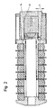
- a reduction in the gap cross-section as a function of the deflection path to avoid a drop in the internal pressure can also, as can be seen from FIG. 2, be achieved by a preferably conical enlargement of the wall thickness D of the cylinder 7a, with an increase in the wall thickness D only to a partial length of It can be an advantage that a smaller widening can be expected towards the end of the cylinder 7a through its end wall.
- the recess 18 in the piston 5 is designed such that an annular wall 19b with a wall thickness d 2 in the central piston region and an annular wall 19a at the front end of the piston is arranged with a wall thickness d 1, the wall thickness d 1 being greater than the wall thickness d 2.
- Two or more recesses 15a and 15b are arranged one behind the other on the outer circumference of the piston 5, an annular gap 14a being formed at the front end of the piston 5 with the inner circumference of the cylinder 7 and at least one further gap 14b in the central region of the piston 5.
- An annular space 16a is arranged between the piston rings 24a and 24b resulting from the recess 15a, and an annular space 16b is arranged behind the piston ring 24b and is connected to the compensating chamber 10 by at least one bore 17. With several turns 15, several piston rings 24, gaps 14 and annular spaces 16 are formed, the last annular space being connected to the compensation chamber.
- the gap 14a changes only slightly since there is no widening in the area of the annular wall 19a due to its large wall thickness d 1 when the pressure rises.
- the design of the piston described above ensures that the damper works properly even with high pressure peaks in the cylinder.
- the desired damping effect at low, medium or high masses to be damped and / or impact speeds is achieved by the corresponding design of the piston.
Abstract
Description
Die Erfindung betrifft einen Puffer, wie er im Oberbegriff von Anspruch 1 gekennzeichnet ist.The invention relates to a buffer as characterized in the preamble of
Derartige Puffer werden meist bei Schienenfahrzeugen verwendet. Durch die DE-A1-320 12 19 ist ein Puffer der eingangs genannten Art bekannt geworden, welcher einen durch eine ringförmige Membrane aus elastomerem Werkstoff veränderlichen kolbenstangenseitigen Ringraum zur Aufnahme der durch den Spalt zwischen Kolben und Zylinderwand durchströmende Dämpfungsflüssigkeit aufweist. Eine derartige Membrane ist wechselnden, dynamischen Belastungen ausgesetzt und nicht auf die Dauer betriebssicher.Such buffers are mostly used in rail vehicles. DE-A1-320 12 19 discloses a buffer of the type mentioned at the outset, which has an annular space on the piston rod side which is variable by means of an annular membrane made of elastomeric material and for receiving the damping fluid flowing through the gap between the piston and the cylinder wall. Such a membrane is exposed to changing, dynamic loads and is not reliable in the long run.
Ausserdem weitet sich der Zylinder durch den Innendruck der Dämpfungsflüssigkeit auf, so dass bei durch Pufferstösse sich erhöhenden Innendruck der Spalt zwischen Kolben und Zylinder-Innenwand sich vergrössert. Dies wirkt sich sehr nachteilig auf die Dämpfungswirkung des Puffers
bei unterschiedlichen Massen bzw. unterschiedlichen Auftreffgeschwindigkeiten der Massen aus.In addition, the cylinder expands due to the internal pressure of the damping fluid, so that the gap between the piston and the inner wall of the cylinder increases when the internal pressure increases due to buffer surges. This has a very disadvantageous effect on the damping effect of the buffer
with different masses or different impact speeds of the masses.
Aufgabe der vorliegenden Erfindung ist die Schaffung eines Puffers der eingangs genannten Art, welcher eine hohe Lebensdauer aufweist, und dessen Dämpfungswirkung sich auch bei Erhöhung des Flüssigkeits-Innendruckes nicht wesentlich verschlechtert.The object of the present invention is to create a buffer of the type mentioned at the outset which has a long service life and whose damping effect does not deteriorate significantly even when the internal pressure of the liquid is increased.
Erfindungsgemäss wird diese Aufgabe durch die kennzeichnenden Merkmale von Anspruch 1 gelöst.According to the invention, this object is achieved by the characterizing features of
Besonders vorteilhafte Ausgestaltungen der Erfindung sind in den abhängigen Ansprüchen gekennzeichnet.Particularly advantageous embodiments of the invention are characterized in the dependent claims.
Die durch höheren Druck entstehende Aufweitung des Zylinders wird durch entsprechende Ausbildung von Kolben und Zylinder derart kompensiert, dass der Spalt zwischen Kolben und Zylinder annähernd gleichbleibt, vorzugsweise sich aber verringert, wodurch die Dämpfer-Wirkung bei unterschiedlich grossen Massen und/oder Auftreffgeschwindigkeiten nicht durch die Aufweitung des Zylinders beeinträchtigt wird.The expansion of the cylinder resulting from higher pressure is compensated for by appropriate design of the piston and cylinder in such a way that the gap between the piston and cylinder remains approximately the same, but preferably decreases, so that the damper effect does not result from the masses and / or impact speeds of different sizes Expansion of the cylinder is impaired.
Die Erfindung ist in Ausführungsbeispielen in den Zeichnungen dargestellt und nachfolgend beschrieben. Es zeigen:
- Fig. 1
- einen Längsschnitt durch einen Puffer
- Fig. 2
- einen Längsschnitt einer Ausführungsvariante von Fig. 1. und
- Fig. 3
- einen Teil-Längsschnitt einer weiteren Ausführungsvariante von Fig. 1 in vergrösserter Darstellung.
- Fig. 1
- a longitudinal section through a buffer
- Fig. 2
- a longitudinal section of an embodiment of Fig. 1 and
- Fig. 3
- a partial longitudinal section of a further embodiment of Fig. 1 in an enlarged view.
Der Puffer gemäss Fig. 1 weist eine in einer Hülse 1 geführte Kolbenstange 2 auf, an dessen einem Ende eine Pufferplatte 3 und am anderen Ende ein Kolben 5 eines hydraulischen Dämpfers 4 angeordnet ist. Die Hülse 1 ist an einem Ende mit einem Flansch 6 versehen, an welchem ein Zylinder 7 des hydraulischen Dämpfers 4 befestigt ist. Zwischen dem Flansch 6 und der Pufferplatte 3 sind Pufferfedern 8 angeordnet, welche vorzugsweise als aus einem elastomeren Werkstoff bestehenden, elastischen Ring-Elementen ausgebildet sind. Zwischen den Ringelementen 8 sind Metallscheiben 9 angeordnet.1 has a piston rod 2 guided in a
Der Dämpfer 4 weist eine Ausgleichskammer 10 auf, welche ringförmig um den Zylinder 7 angeordnet ist. Die beidseitige Begrenzung der Ausgleichskammer 10 besteht auf der einen Seite durch den Flansch 6 und auf der anderen Seite durch eine an dem Zylinder 7 angeordnete, ringförmige Scheibe 11. Eine kreiszylindrische Aussenwandung 12 ist jeweils am Aussenumfang des Flansches 6 und der ringförmigen Scheibe 7 befestigt und bildet den äusseren Mantel der Ausgleichskammer 10.The
Der Aussenumfang des Kolbens 5 bildet mit dem Innenumfang 13 des Zylinders 7 einen ringförmigen Spalt 14.The outer circumference of the
Eine Ausdrehung 15 am Kolben 5 bildet mit der Zylinder-Innenwand 13 in der gezeigten Endstellung einen Ringraum 16, welcher durch mindestens eine Bohrung 17 mit der Ausgleichskammer 10 verbunden ist.A recess 15 on the
Am stirnseitigen Ende des Kolbens 5 ist eine Ausnehmung 18 angeordnet, wodurch eine ringförmige Wand 19 entsteht, welche abhängig vom Innendruck elastisch verformbar ist.At the front end of the
Der Innenraum 20 des Zylinders 7 mit dem Ringraum 16 ist ganz und die Ausgleichskammer 10 teilweise mit einer Dämpferflüssigkeit 21, vorzugsweise einem Hydraulik-Oel, gefüllt, wobei in der Ausgleichskammer 10 ein Gaspolster 22 vorzugsweise aus Stickstoff angeordnet ist.The interior 20 of the
Beim Einfahren des Kolbens 5 strömt das Hydraulik-Oel 21 durch den Spalt 14 in den Ringraum 16, wobei das überschüssige Volumen in die Ausgleichskammer 10 gelangt und dort durch Komprimierung das Volumen des Gaspolsters 22 verringert.When the
Beim Aufstossen der zu dämpfenden Massen bzw. beim Einfahren des Kolbens 5 steigt der Innendruck im Zylinder 7 in Abhängigkeit der Aufstossgeschwindigkeit, wodurch sich dieser im Durchmesser aufweitet. Gleichzeitig wird durch den steigenden Innendruck die ringförmige Wand 19 des Kolbens 5 nach aussen elastisch aufgeweitet, so dass die Aufweitung des Zylinders mindestens teilweise kompensiert wird und der Spalt 14 sich zumindest nur unwesentlich vergrössert oder gleiche bleibt. Vorteilhafterweise sollte bei steigendem Innendruck eine Verkleinerung des Spaltes 14 erfolgen, um die gleiche Dämpfungswirkung zu erreichen. Dies kann dadurch erreicht werden, indem die Wandstärke d der ringförmigen Wand 19 am Kolben 5 entsprechend kleiner gewählt wird als die Wandstärke D der Zylinderwand 23.When the masses to be damped are pushed open or when the
Mit zunehmendem Einfederungsweg nimmt die Geschwindigkeit der zu verzögernden Massen ab. Um die Verzögerung hoch zu halten, muss der Spaltquerschnitt in Abhängigkeit des Einfederungsweges abnehmen. Ein mindestens gleichbleibender oder sich verringernder Spalt kann zusätzlich zur Ausbildung des Kolbens oder auch allein durch die geometrische Ausbildung des Innenraumes des Zylinders 7 in Längsrichtung erreicht werden.The speed of the masses to be decelerated decreases with increasing deflection. In order to keep the deceleration high, the gap cross-section must decrease depending on the deflection path. An at least constant or decreasing gap can be achieved in addition to the design of the piston or simply by the geometric design of the interior of the
Hierbei wird der in Fig. 1 strichpunktiert eingezeichnete Innenumfang 13a des Zylinders 7 in Längsrichtung der Einfederung ganz oder mindestens teilweise konisch zusammen-laufend ausgebildet, so dass sich der Innenumfang und somit die Spaltgrösse bei konstantem Innendruck verringert.In this case, the inner circumference 13a of the
Eine Verringerung des Spaltquerschnittes in Abhängigkeit des Einfederungsweges zur Vermeidung eines Abfalles des Innendrucks kann auch, wie aus Fig. 2 ersichtlich, durch eine vorzugsweise konische Vergrösserung der Wandstärke D des Zylinders 7a erreicht werden, wobei eine Vergrösserung der Wandstärke D auch nur auf eine Teillänge von Vorteil sein kann, da gegen Ende des Zylinders 7a durch deren Endwand mit einer geringeren Aufweitung zu rechnen ist.A reduction in the gap cross-section as a function of the deflection path to avoid a drop in the internal pressure can also, as can be seen from FIG. 2, be achieved by a preferably conical enlargement of the wall thickness D of the cylinder 7a, with an increase in the wall thickness D only to a partial length of It can be an advantage that a smaller widening can be expected towards the end of the cylinder 7a through its end wall.
Bei einer Kombination dieser Ausbildung des Zylinders 7a gemäss Fig. 2 und der beschriebenen Ausbildung des Kolbens 5 ergibt sich während des Kolbenweges eine Verringerung des Spaltes 14, wodurch die Aenderung der Dämpfungsverhältnisse bei unterschiedlich abzudämpfenden Massen und/oder Auftreffgeschwindigkeiten reduziert wird. -Combining this design of the cylinder 7a according to FIG. 2 and the described design of the
Die in Fig. 3 gezeigte Ausführungsvariante zeigt eine besonders vorteilhafte Ausbildung des Kolbens 5. Die Ausnehmung 18 im Kolben 5 ist dabei derartig ausgebildet, dass im mittleren Kolbenbereich eine ringförmige Wand 19b mit einer Wanddicke d 2 und am stirnseitigen Ende des Kolbens eine ringförmige Wand 19a mit einer Wanddicke d 1 angeordnet ist, wobei die Wanddicke d 1 grösser ist als die Wanddicke d 2.3 shows a particularly advantageous embodiment of the
Am Aussenumfang des Kolbens 5 sind hintereinander zwei oder mehrere Ausdrehungen 15a und 15b angeordnet, wobei am stirnseitigen Ende des Kolbens 5 mit dem Innenumfang des Zylinders 7 ein ringförmiger Spalt 14a und im mittleren Bereich des Kolbens 5 mindestens ein weiterer Spalt 14b gebildet wird. Zwischen den durch die Ausdrehung 15a entstehenden Kolbenringen 24a und 24b ist ein Ringraum 16a und hinter dem Kolbenring 24b ein Ringraum 16b angeordnet, welcher durch mindestens eine Bohrung 17 mit der Ausgleichskammer 10 verbunden ist. Bei mehreren Ausdrehungen 15 entstehen auch mehrere Kolbenringe 24, Spalte 14 und Ringräume 16, wobei der letzte Ringraum mit der Ausgleichskammer verbunden ist.Two or
Durch die unterschiedlichen Wanddicken des Kolbens 5 entstehen bei unterschiedlich grossen Aufstoss-Massen und/oder Auftreffgeschwindigkeiten unterschiedliche Innendrücke der Dämpferflüssigkeit 21 verbunden mit unterschiedlichen Verformungen des Kolbens 5 und somit unterschiedliche Veränderungen der Spalte 14a und 14b, wobei durch die Wahl der Wandstärken gewünschte Dämpfungs-Charakteristiken erzielbar sind.Due to the different wall thicknesses of the
Der Spalt 14a verändert sich nur geringfügig, da bei Druckanstieg keine Aufweitung im Bereich der ringförmigen Wand 19a durch deren grosse Wandstärke d 1 stattfindet.The
Bei geringem Druckanstieg - geringe Massen bzw. Auftreffgeschwindigkeiten - entsteht auch beim Spalt 14b keine Veränderung, da noch keine Aufweitung des Kolbens 5 stattfindet. Die Dämpfwirkung ist hierbei durch die gewählten Spaltgrössen bestimmt. Bei stärkerem Innendruckanstieg weitet sich der Kolben im Bereich der ringförmigen Wand 19b auf, so dass trotz Aufweiten des Zylinders 7 der Spalt 14b sich nicht vergrössert bzw. sich vorzugsweise verringert. In dem Ringraum 16a steigt der Innendruck durch den Spalt 14a nicht gleich proportional zum übrigen Innendruck im Zylinder 7.With a slight increase in pressure - low masses or impact speeds - there is no change even in the
Bei sehr starkem Druckanstieg verhindert der Druck im Ringraum 16a ein zu starkes Aufweiten des Kolbens 5, so dass eine Verringerung des Spaltes 14b bis Null vermieden wird.When the pressure rises very sharply, the pressure in the
Die vorgängig beschriebene Ausbildung des Kolbens gewährleistet ein einwandfreies Arbeiten des Dämpfers auch bei hohen Druckspitzen im Zylinder. Die jeweils gewünschte Dämpfwirkung bei niedrigen, mittleren oder hohen abzudämpfenden Massen und/oder Auftreffgeschwindigkeiten wird durch die entpsprechende Ausbildung des Kolbens erreicht.The design of the piston described above ensures that the damper works properly even with high pressure peaks in the cylinder. The desired damping effect at low, medium or high masses to be damped and / or impact speeds is achieved by the corresponding design of the piston.
Claims (9)
Priority Applications (1)
| Application Number | Priority Date | Filing Date | Title |
|---|---|---|---|
| AT91104936T ATE99612T1 (en) | 1990-04-09 | 1991-03-28 | BUFFER WITH A HYDRAULIC DAMPER. |
Applications Claiming Priority (2)
| Application Number | Priority Date | Filing Date | Title |
|---|---|---|---|
| DE4011439A DE4011439C2 (en) | 1990-04-09 | 1990-04-09 | Buffer with a hydraulic damper |
| DE4011439 | 1990-04-09 |
Publications (2)
| Publication Number | Publication Date |
|---|---|
| EP0451630A1 true EP0451630A1 (en) | 1991-10-16 |
| EP0451630B1 EP0451630B1 (en) | 1994-01-05 |
Family
ID=6404059
Family Applications (1)
| Application Number | Title | Priority Date | Filing Date |
|---|---|---|---|
| EP91104936A Expired - Lifetime EP0451630B1 (en) | 1990-04-09 | 1991-03-28 | Buffer with a hydraulic damper |
Country Status (3)
| Country | Link |
|---|---|
| EP (1) | EP0451630B1 (en) |
| AT (1) | ATE99612T1 (en) |
| DE (2) | DE4011439C2 (en) |
Cited By (6)
| Publication number | Priority date | Publication date | Assignee | Title |
|---|---|---|---|---|
| US5908123A (en) * | 1997-01-21 | 1999-06-01 | Keystone Industries, Inc. | Rail car buffer and method |
| US5927523A (en) * | 1997-05-30 | 1999-07-27 | Keystone Industries, Inc. | Rail car buffer |
| EP0933279A1 (en) * | 1998-02-03 | 1999-08-04 | Keystone Industries, Inc. | Rail car buffer |
| EP1738985A1 (en) | 2005-06-30 | 2007-01-03 | Schwab Verkehrstechnik AG | Damping device for drawing and/or buffing devices of railway vehicles |
| EP1900594A1 (en) | 2006-09-14 | 2008-03-19 | Schwab Verkehrstechnik AG | Dampening arrangement for drawing and/or buffing devices of railway vehicles and drawing and/or buffing devices of railway vehicles with a dampening arrangement |
| CN103523045A (en) * | 2013-10-25 | 2014-01-22 | 齐齐哈尔轨道交通装备有限责任公司 | Damping type buffer of goods wagon and goods wagon |
Families Citing this family (1)
| Publication number | Priority date | Publication date | Assignee | Title |
|---|---|---|---|---|
| DE4117943A1 (en) * | 1991-05-31 | 1992-12-03 | Josef Niklaus | SPRING WITH SHOCK ABSORBER FOR RAILWAY VEHICLES |
Citations (3)
| Publication number | Priority date | Publication date | Assignee | Title |
|---|---|---|---|---|
| DE555012C (en) * | 1930-02-25 | 1932-07-18 | Rheinische Metallw & Maschf | Fluid brake |
| FR1236997A (en) * | 1958-10-06 | 1960-07-22 | Swindon Tool Company Ltd | Buffers for railway vehicles |
| EP0268061A1 (en) * | 1986-11-12 | 1988-05-25 | Waggon Union GmbH | Buffer device for the elastic absorption of shocks |
Family Cites Families (4)
| Publication number | Priority date | Publication date | Assignee | Title |
|---|---|---|---|---|
| DE471804C (en) * | 1928-02-05 | 1929-02-16 | Rheinische Metallw & Maschf | Fluid brake, especially for buffers on railway vehicles |
| GB888878A (en) * | 1958-09-25 | 1962-02-07 | Dowty Hydraulic Units Ltd | Improvements relating to railway vehicle buffers |
| JPS53131620A (en) * | 1977-07-18 | 1978-11-16 | Japan Steel Works Ltd:The | Shock absorber for railway vehicle |
| IT1135440B (en) * | 1981-02-12 | 1986-08-20 | Gomma Antivibranti Applic | BUFFER FOR RAILWAY VEHICLES |
-
1990
- 1990-04-09 DE DE4011439A patent/DE4011439C2/en not_active Expired - Fee Related
-
1991
- 1991-03-28 AT AT91104936T patent/ATE99612T1/en not_active IP Right Cessation
- 1991-03-28 EP EP91104936A patent/EP0451630B1/en not_active Expired - Lifetime
- 1991-03-28 DE DE91104936T patent/DE59100792D1/en not_active Expired - Fee Related
Patent Citations (3)
| Publication number | Priority date | Publication date | Assignee | Title |
|---|---|---|---|---|
| DE555012C (en) * | 1930-02-25 | 1932-07-18 | Rheinische Metallw & Maschf | Fluid brake |
| FR1236997A (en) * | 1958-10-06 | 1960-07-22 | Swindon Tool Company Ltd | Buffers for railway vehicles |
| EP0268061A1 (en) * | 1986-11-12 | 1988-05-25 | Waggon Union GmbH | Buffer device for the elastic absorption of shocks |
Cited By (7)
| Publication number | Priority date | Publication date | Assignee | Title |
|---|---|---|---|---|
| US5908123A (en) * | 1997-01-21 | 1999-06-01 | Keystone Industries, Inc. | Rail car buffer and method |
| US5927523A (en) * | 1997-05-30 | 1999-07-27 | Keystone Industries, Inc. | Rail car buffer |
| EP0933279A1 (en) * | 1998-02-03 | 1999-08-04 | Keystone Industries, Inc. | Rail car buffer |
| US6047839A (en) * | 1998-02-03 | 2000-04-11 | Huggins; Russell J. | Rail car buffer |
| EP1738985A1 (en) | 2005-06-30 | 2007-01-03 | Schwab Verkehrstechnik AG | Damping device for drawing and/or buffing devices of railway vehicles |
| EP1900594A1 (en) | 2006-09-14 | 2008-03-19 | Schwab Verkehrstechnik AG | Dampening arrangement for drawing and/or buffing devices of railway vehicles and drawing and/or buffing devices of railway vehicles with a dampening arrangement |
| CN103523045A (en) * | 2013-10-25 | 2014-01-22 | 齐齐哈尔轨道交通装备有限责任公司 | Damping type buffer of goods wagon and goods wagon |
Also Published As
| Publication number | Publication date |
|---|---|
| DE4011439A1 (en) | 1991-10-10 |
| DE59100792D1 (en) | 1994-02-17 |
| ATE99612T1 (en) | 1994-01-15 |
| EP0451630B1 (en) | 1994-01-05 |
| DE4011439C2 (en) | 1994-01-20 |
Similar Documents
| Publication | Publication Date | Title |
|---|---|---|
| DE3932258C2 (en) | Hydraulic shock absorber with a piston seal for improved initial response | |
| DE3932669C2 (en) | Hydraulic shock absorber | |
| DE2759943C2 (en) | Sealing arrangement for the piston rod of a shock absorber | |
| DE965003C (en) | Hydraulic piston shock absorber | |
| DE2750667B1 (en) | Air spring for motor vehicles | |
| EP1215414B1 (en) | Piston-cylinder aggregate with a damping force proportional to the speed | |
| DE3923512A1 (en) | SHOCK VALVE WITH STRONG PROGRESSIVE STEEL CHARACTERISTICS, ESPECIALLY FOR STEERING DAMPERS FOR MOTORCYCLES | |
| DE1134253B (en) | Elastic piston for vibration damper | |
| DE3818811A1 (en) | GAS SPRING WITH SEVERAL PRESSURE SPACES | |
| DE1505478A1 (en) | Infinitely adjustable shock absorber, especially for motor vehicles | |
| DE102005045267B3 (en) | Damper with adjustable damping force for damping vibrations has bypass channel hydraulically parallel to flow connection | |
| WO2016074867A1 (en) | Damping valve for a vibration damper | |
| EP0451630B1 (en) | Buffer with a hydraulic damper | |
| DE19738617C2 (en) | Shock absorbers for motor vehicles | |
| DE1780074A1 (en) | Wheel suspension for motor vehicles | |
| DE4335788A1 (en) | Sealing arrangement | |
| DE2822590C3 (en) | Angularly movable guide bearing, in particular for Mc-Pherson struts of motor vehicles | |
| WO2022083811A1 (en) | Working cylinder with end-position damping, and damping piston ring | |
| DE2227042C3 (en) | Sealing arrangement | |
| EP0525688B1 (en) | Control valve for controlling and shut off fluid flow | |
| DE3905777A1 (en) | Sealing ring | |
| DE3421601C2 (en) | ||
| DE2554445A1 (en) | CONTROL VALVE | |
| DE2041597A1 (en) | Braking device for hydraulic or pneumatic working cylinders with one or two-sided end position braking | |
| DE3438163C2 (en) |
Legal Events
| Date | Code | Title | Description |
|---|---|---|---|
| PUAI | Public reference made under article 153(3) epc to a published international application that has entered the european phase |
Free format text: ORIGINAL CODE: 0009012 |
|
| 17P | Request for examination filed |
Effective date: 19910328 |
|
| AK | Designated contracting states |
Kind code of ref document: A1 Designated state(s): AT BE CH DE DK ES FR GB IT LI NL SE |
|
| 17Q | First examination report despatched |
Effective date: 19930331 |
|
| GRAA | (expected) grant |
Free format text: ORIGINAL CODE: 0009210 |
|
| AK | Designated contracting states |
Kind code of ref document: B1 Designated state(s): AT BE CH DE DK ES FR GB IT LI NL SE |
|
| PG25 | Lapsed in a contracting state [announced via postgrant information from national office to epo] |
Ref country code: SE Effective date: 19940105 Ref country code: GB Effective date: 19940105 Ref country code: ES Free format text: THE PATENT HAS BEEN ANNULLED BY A DECISION OF A NATIONAL AUTHORITY Effective date: 19940105 Ref country code: DK Effective date: 19940105 Ref country code: BE Effective date: 19940105 |
|
| REF | Corresponds to: |
Ref document number: 99612 Country of ref document: AT Date of ref document: 19940115 Kind code of ref document: T |
|
| REF | Corresponds to: |
Ref document number: 59100792 Country of ref document: DE Date of ref document: 19940217 |
|
| ET | Fr: translation filed | ||
| ITF | It: translation for a ep patent filed |
Owner name: DE DOMINICIS & MAYER S.R.L. |
|
| PG25 | Lapsed in a contracting state [announced via postgrant information from national office to epo] |
Ref country code: AT Effective date: 19940328 |
|
| GBV | Gb: ep patent (uk) treated as always having been void in accordance with gb section 77(7)/1977 [no translation filed] |
Effective date: 19940105 |
|
| PLBE | No opposition filed within time limit |
Free format text: ORIGINAL CODE: 0009261 |
|
| STAA | Information on the status of an ep patent application or granted ep patent |
Free format text: STATUS: NO OPPOSITION FILED WITHIN TIME LIMIT |
|
| 26N | No opposition filed | ||
| PGFP | Annual fee paid to national office [announced via postgrant information from national office to epo] |
Ref country code: FR Payment date: 19970214 Year of fee payment: 7 |
|
| PGFP | Annual fee paid to national office [announced via postgrant information from national office to epo] |
Ref country code: DE Payment date: 19970220 Year of fee payment: 7 |
|
| PGFP | Annual fee paid to national office [announced via postgrant information from national office to epo] |
Ref country code: NL Payment date: 19970224 Year of fee payment: 7 |
|
| PGFP | Annual fee paid to national office [announced via postgrant information from national office to epo] |
Ref country code: CH Payment date: 19970226 Year of fee payment: 7 |
|
| PG25 | Lapsed in a contracting state [announced via postgrant information from national office to epo] |
Ref country code: LI Free format text: LAPSE BECAUSE OF NON-PAYMENT OF DUE FEES Effective date: 19980331 Ref country code: FR Free format text: THE PATENT HAS BEEN ANNULLED BY A DECISION OF A NATIONAL AUTHORITY Effective date: 19980331 Ref country code: CH Free format text: LAPSE BECAUSE OF NON-PAYMENT OF DUE FEES Effective date: 19980331 |
|
| PG25 | Lapsed in a contracting state [announced via postgrant information from national office to epo] |
Ref country code: NL Free format text: LAPSE BECAUSE OF NON-PAYMENT OF DUE FEES Effective date: 19981001 |
|
| REG | Reference to a national code |
Ref country code: CH Ref legal event code: PL |
|
| NLV4 | Nl: lapsed or anulled due to non-payment of the annual fee |
Effective date: 19981001 |
|
| PG25 | Lapsed in a contracting state [announced via postgrant information from national office to epo] |
Ref country code: DE Free format text: LAPSE BECAUSE OF NON-PAYMENT OF DUE FEES Effective date: 19981201 |
|
| REG | Reference to a national code |
Ref country code: FR Ref legal event code: ST |
|
| PG25 | Lapsed in a contracting state [announced via postgrant information from national office to epo] |
Ref country code: IT Free format text: LAPSE BECAUSE OF NON-PAYMENT OF DUE FEES;WARNING: LAPSES OF ITALIAN PATENTS WITH EFFECTIVE DATE BEFORE 2007 MAY HAVE OCCURRED AT ANY TIME BEFORE 2007. THE CORRECT EFFECTIVE DATE MAY BE DIFFERENT FROM THE ONE RECORDED. Effective date: 20050328 |