EP0451602B1 - Continuous process for upgrading polymer solutions for a requested specification of residual solvents - Google Patents
Continuous process for upgrading polymer solutions for a requested specification of residual solvents Download PDFInfo
- Publication number
- EP0451602B1 EP0451602B1 EP91104728A EP91104728A EP0451602B1 EP 0451602 B1 EP0451602 B1 EP 0451602B1 EP 91104728 A EP91104728 A EP 91104728A EP 91104728 A EP91104728 A EP 91104728A EP 0451602 B1 EP0451602 B1 EP 0451602B1
- Authority
- EP
- European Patent Office
- Prior art keywords
- flow tube
- flow
- tube
- polymer
- product
- Prior art date
- Legal status (The legal status is an assumption and is not a legal conclusion. Google has not performed a legal analysis and makes no representation as to the accuracy of the status listed.)
- Expired - Lifetime
Links
Images

Classifications
-
- B—PERFORMING OPERATIONS; TRANSPORTING
- B01—PHYSICAL OR CHEMICAL PROCESSES OR APPARATUS IN GENERAL
- B01D—SEPARATION
- B01D1/00—Evaporating
- B01D1/22—Evaporating by bringing a thin layer of the liquid into contact with a heated surface
- B01D1/222—In rotating vessels; vessels with movable parts
- B01D1/223—In rotating vessels; vessels with movable parts containing a rotor
- B01D1/225—In rotating vessels; vessels with movable parts containing a rotor with blades or scrapers
- B01D1/226—In rotating vessels; vessels with movable parts containing a rotor with blades or scrapers in the form of a screw or with helical blade members
-
- B—PERFORMING OPERATIONS; TRANSPORTING
- B01—PHYSICAL OR CHEMICAL PROCESSES OR APPARATUS IN GENERAL
- B01D—SEPARATION
- B01D3/00—Distillation or related exchange processes in which liquids are contacted with gaseous media, e.g. stripping
- B01D3/06—Flash distillation
-
- C—CHEMISTRY; METALLURGY
- C08—ORGANIC MACROMOLECULAR COMPOUNDS; THEIR PREPARATION OR CHEMICAL WORKING-UP; COMPOSITIONS BASED THEREON
- C08F—MACROMOLECULAR COMPOUNDS OBTAINED BY REACTIONS ONLY INVOLVING CARBON-TO-CARBON UNSATURATED BONDS
- C08F6/00—Post-polymerisation treatments
- C08F6/02—Neutralisation of the polymerisation mass, e.g. killing the catalyst also removal of catalyst residues
-
- C—CHEMISTRY; METALLURGY
- C08—ORGANIC MACROMOLECULAR COMPOUNDS; THEIR PREPARATION OR CHEMICAL WORKING-UP; COMPOSITIONS BASED THEREON
- C08G—MACROMOLECULAR COMPOUNDS OBTAINED OTHERWISE THAN BY REACTIONS ONLY INVOLVING UNSATURATED CARBON-TO-CARBON BONDS
- C08G77/00—Macromolecular compounds obtained by reactions forming a linkage containing silicon with or without sulfur, nitrogen, oxygen or carbon in the main chain of the macromolecule
- C08G77/04—Polysiloxanes
- C08G77/32—Post-polymerisation treatment
- C08G77/34—Purification
Definitions
- the invention relates to a continuous process for concentrating polymer solutions up to a required degree of specification of residual solvents, the product being heated under pressure and then expanded in a throttling element with the formation of steam into a heated flow tube and thereby being concentrated.
- a large part of the concentration process can also be carried out in a simple, heatable flow tube, which is preferably continuously coiled (DE-A-1 667 051 corresponding to GB-A-1 243 011 and DE-A-1 921 045 according to GB-A-1 282 992).
- a polymer solution is heated under excess pressure, expanded via a nozzle in the event of vapor formation, and the vapor-liquid mixture is then conveyed through the coiled flow tube, the product being further concentrated, to a minimum residual solvent content of 1% by weight.
- a cyclone separator follows the flow tube, in which the vapors are separated from the polymer.
- the polymer melt is then fed to a twin-screw machine, in which it is cleaned up to the specification requirement for the residual solvent.
- the disadvantage of this method is the separator and the screw machine.
- the vapor-liquid mixture flows out of the flow pipe into the separator at high speed, often at the speed of sound and subsequent expansion.
- the product splashes everywhere on the walls and sticks here because the shear forces are lacking, and over time crusts and often mountains of coastline build up. Part of the product can also be carried into the vapor tubes and settle there and block the tubes. For this reason, the concentration options in the helical tube are often not fully exploited, but are only concentrated there to such an extent that the product in the following separator is still easy to flow.
- This object is achieved in that the concentration in the first flow tube is carried out as far as possible that the product is then introduced at an angle into a second, directly downstream, heatable flow tube which has self-cleaning elements and at least 50 times the flow cross-section of the first flow tube and brought to the desired final concentration, and the separation of the vapor stream from the polymer stream takes place only behind the second flow tube.
- the first flow tube can be any, for example a long straight, a meandering or preferably a continuously coiled flow tube.
- Either a rotary tube with a self-cleaning knife shaft or a self-cleaning paddle screw device is used as the second flow tube.
- the main advantage of the proposed method is that the deposition and cleaning process are combined in one apparatus. This eliminates the problem of crust formation in the separator and you can really concentrate in the first flow tube as much as the apparatus allows.
- the steam-liquid jet emerging from the first flow tube at high flow velocity strikes the wall of the second flow tube or the paddle screws. This breaks the radiation energy.
- the sticky polymer deposits on the walls and is carried on from there through the scraping elements and the pipe slope to the outlet, with the remaining concentration taking place.
- Another advantage of the method is that the equipment used is much cheaper than a twin-screw machine. They also have an even more favorable surface / volume ratio.
- a polymer solution passes from a heatable container 1 via a line 2 into a throttle body 3 designed as a relaxation nozzle, in front of which an inert gas line 5 provided with a shut-off valve 4 also opens into line 2.
- the expansion nozzle 3 is arranged at the entrance of a flow tube 7 provided with a heating jacket 6 and designed as a continuous coil of 20 ° inclination.
- the polymer solution is further concentrated in this flow tube 7. With an average exit speed of 80 m / s, this mixture of concentrate and vapors is flung vertically against the inner wall 12 of a flow tube 9 designed as a rotary tube, the flow cross section of which is 80 times that of the flow tube 7.
- a rotary tube is used as the second flow tube instead of the paddle screw device: Case length 1000 mm Rotary tube diameter 200 mm Diameter of the scraper knife 50 mm Inclination of the rotary tube 10 ° number of revolutions 30 rpm Flow cross-section 13,000 mm2 Heating medium Marlotherm oil Heating medium temperature 300 ° C Residual solvent content 500 ppm
Description
Die Erfindung betrifft ein kontinuierliches Verfahren zum Aufkonzentrieren von Polymerlösungen bis zu einem geforderten Spezifikationsgrad an Restlösungsmitteln, wobei das Produkt unter Druck aufgeheizt und anschließend in einem Drosselorgan unter Dampfbildung in ein beheiztes Strömungsrohr hinein entspannt und dabei aufkonzentriert wird.The invention relates to a continuous process for concentrating polymer solutions up to a required degree of specification of residual solvents, the product being heated under pressure and then expanded in a throttling element with the formation of steam into a heated flow tube and thereby being concentrated.
Bei der Aufkonzentrierung von Polymerlösungen bis zu Restlösungsmittelgehalten im ppm-Bereich stellen sich mehrere Probleme:
Polymere sind sehr empfindlich gegenüber hohen Temperaturen. Es kann zu Nachpolymerisation, Stippenbildung und Farbveränderungen kommen. Dementsprechend werden kurze Verweilzeiten für den Aufkonzentrierungsprozeß verlangt, was einen guten Warme- und Stoffaustausch voraussetzt. Zum Ende des Prozesses hin wird die Viskosität der Schmelze sehr hoch und kann Werte bis zu 1000 Pa.s annehmen. Die Spezifikationsanforderungen an Polymere liegen im allgemeinen bei Restlösungsmittelgehalten im ppm-Bereich. Dies bedingt, daß auch in der Endphase des Prozesses, wenn die Viskosität im Bereich 100 bis 1000 Pa.s liegt, noch eine gute Durchmischung des Produkts mit laufender Oberflächenerneuerung stattfindet. Bei zu langer Verweilzeit in dieser Prozeßphase mit den hohen Temperaturen würde das Produkt ansonsten thermisch stark geschädigt.Several problems arise when concentrating polymer solutions down to residual solvent contents in the ppm range:
Polymers are very sensitive to high temperatures. Post-polymerization, speck formation and color changes can occur. Accordingly, short dwell times are required for the concentration process, which requires a good heat and material exchange. At the end of the process, the viscosity of the melt becomes very high and can reach values of up to 1000 Pa.s. The specification requirements for polymers are generally in the ppm range for residual solvent contents. This means that even in the final phase of the process, when the viscosity is in the range of 100 to 1000 Pa.s, the product is still thoroughly mixed with ongoing surface renewal. If the dwell time in this process phase is too long with the high temperatures, the product would otherwise be severely damaged thermally.
Es hat sich herausgestellt, daß man einen großen Teil des Aufkonzentrierungsprozesses auch in einem einfachen, beheizbaren Strömungsrohr, welches vorzugsweise stetig gewendelt ist, durchführen kann (DE-A-1 667 051 entsprechend GB-A-1 243 011 und DE-A-1 921 045 entsprechend GB-A-1 282 992). Hierbei wird eine Polymerlösung unter Überdruck aufgeheizt, über eine Düse bei Dampfbildung entspannt und das Dampf-Flüssigkeits-Gemisch anschließend durch das gewendelte Strömungsrohr gefördert, wobei das Produkt weiter aufkonzentriert wird, und zwar bis zu einem minimalen Restlösungsmittelgehalt von 1 Gew.-%. Dem Strömungsrohr folgt ein Zyklonabscheider, in dem die Brüden vom Polymer abgetrennt werden. Die Polymerschmelze wird dann einer Doppelwellenschneckenmaschine zugeführt, in der sie bis auf die Spezifikationsanforderung für das Restlösemittel gereinigt wird. Nachteilig bei diesem Verfahren ist der Abscheider und die Schneckenmaschine. Das Dampf-Flüssigkeits-Gemisch strömt mit hoher Geschwindigkeit, oft mit Schallgeschwindigkeit und nachfolgender Expansion, aus dem Strömungsrohr in den Abscheider hinein. Dabei spritzt das Produkt überall an die Wände und bleibt hier haften, weil die Scherkräfte fehlen, und es bauen sich so im Laufe der Zeit Krusten und vielfach auch Kustenberge auf. Ein Teil des Produktes kann auch in die Brüdenrohre mitgerissen werden und sich dort absetzen und die Rohre verstopfen. Deshalb nützt man oft die Aufkonzentrierungsmöglichkeiten im Wendelrohr nicht voll aus, sondern konzentriert dort nur so weit auf, daß das Produkt im folgenden Abscheider noch gut fließfähig ist.It has been found that a large part of the concentration process can also be carried out in a simple, heatable flow tube, which is preferably continuously coiled (DE-A-1 667 051 corresponding to GB-A-1 243 011 and DE-A-1 921 045 according to GB-A-1 282 992). Here, a polymer solution is heated under excess pressure, expanded via a nozzle in the event of vapor formation, and the vapor-liquid mixture is then conveyed through the coiled flow tube, the product being further concentrated, to a minimum residual solvent content of 1% by weight. A cyclone separator follows the flow tube, in which the vapors are separated from the polymer. The polymer melt is then fed to a twin-screw machine, in which it is cleaned up to the specification requirement for the residual solvent. The disadvantage of this method is the separator and the screw machine. The vapor-liquid mixture flows out of the flow pipe into the separator at high speed, often at the speed of sound and subsequent expansion. The product splashes everywhere on the walls and sticks here because the shear forces are lacking, and over time crusts and often mountains of coastline build up. Part of the product can also be carried into the vapor tubes and settle there and block the tubes. For this reason, the concentration options in the helical tube are often not fully exploited, but are only concentrated there to such an extent that the product in the following separator is still easy to flow.
Es besteht die Aufgabe, das Verfahren der eingangs genannten Art dahingehend zu verbessern, daß Krustenbildung vermieden und eine bessere Ausbeute erzielt wird.The object is to improve the process of the type mentioned at the outset so that crust formation is avoided and a better yield is achieved.
Gelöst wird diese Aufgabe dadurch, daß im ersten Strömungsrohr die Aufkonzentrierung möglichst weitgehend durchgeführt wird, daß das Produkt dann unter einem Winkel in ein zweites, direkt nachgeordnetes, beheizbares Strömungsrohr, welches selbstreinigende Elemente und mindestens den 50-fachen Strömungsquerschnitt des ersten Strömungsrohres aufweist, eingebracht und auf die gewünschte Endkonsentration gebracht wird, und wobei die Abtrennung des Brüdenstromes vom Polymerstrom erst hinter dem zweiten Strömungsrohr erfolgt.This object is achieved in that the concentration in the first flow tube is carried out as far as possible that the product is then introduced at an angle into a second, directly downstream, heatable flow tube which has self-cleaning elements and at least 50 times the flow cross-section of the first flow tube and brought to the desired final concentration, and the separation of the vapor stream from the polymer stream takes place only behind the second flow tube.
Beim ersten Strömungsrohr kann es sich um ein beliebiges handeln, beispielsweise ein langes gerades, ein mäanderförmiges oder vorzugsweise um ein stetig gewendeltes Strömungsrohr.The first flow tube can be any, for example a long straight, a meandering or preferably a continuously coiled flow tube.
Als zweites Strömungsrohr wird entweder ein Drehrohr mit einer selbstreinigenden Messerwelle oder ein selbstreinigender Paddelschneckenapparat verwendet.Either a rotary tube with a self-cleaning knife shaft or a self-cleaning paddle screw device is used as the second flow tube.
Der Hauptvorteil des vorgeschlagenen Verfahrens besteht darin, daß Abscheidungs- und und Reinigungsprozeß in einem Apparat zusammengefaßt sind. Dabei entfällt das Problem der Krustenbildung im Abscheider und man kann im ersten Strömungsrohr wirklich so weit aufkonzentrieren, wie es der Apparat zuläßt. Der aus dem ersten Strömungsrohr mit hoher Strömungsgeschwindigkeit austretende Dampf-Flüssigkeitsstrahl trifft direkt auf die Wand des zweiten Strömungsrohres bzw. die Paddelschnecken. Dabei wird die Strahlenergie gebrochen. Das klebrige Polymer scheidet sich an den Wanden ab und wird von dort durch die schabenden Elemente und die Rohrneigung zum Auslaß weitergeführt, wobei die Restaufkonzentrierung stattfindet. Der Dampfstrahl wird umgelenkt, verliert auf dem Wege zum Auslaß infolge des gegenüber dem ersten Strömungsrohr wesentlich vergrößerten Strömungsquerschnittes weitgehend seine kinetische Energie und ist damit nicht mehr in der Lage, etwa mitgerissene Flüssigkeitströpfchen zu halten, die dann ebenfalls an der Wand oder an den Schaberelementen abgeschieden werden.The main advantage of the proposed method is that the deposition and cleaning process are combined in one apparatus. This eliminates the problem of crust formation in the separator and you can really concentrate in the first flow tube as much as the apparatus allows. The steam-liquid jet emerging from the first flow tube at high flow velocity strikes the wall of the second flow tube or the paddle screws. This breaks the radiation energy. The sticky polymer deposits on the walls and is carried on from there through the scraping elements and the pipe slope to the outlet, with the remaining concentration taking place. The steam jet is deflected, largely loses its kinetic energy on the way to the outlet as a result of the flow cross-section which is substantially larger than that of the first flow tube and is therefore no longer able to hold liquid droplets which are entrained and which are then likewise deposited on the wall or on the scraper elements become.
Ein weiterer Vorteil des Verfahrens besteht darin, daß die verwendeten Apparaturen wesentlich kostengünstiger sind als eine Doppelwellenschneckenmaschine. Außerdem besitzen sie ein noch günstigeres Oberflächen-/Volumenverhältnis.Another advantage of the method is that the equipment used is much cheaper than a twin-screw machine. They also have an even more favorable surface / volume ratio.
In einigen Fällen kann es möglich sein, daß zu wenig Lösemittel vorhanden ist, um den Prozeß durchzuführen oder der geforderte Spezifikationsgrad trotz aller eingeleiteter Maßnahmen nicht erreicht wird.In some cases it may be that there is not enough solvent to carry out the process or that the required level of specification is not achieved despite all the measures taken.
In diesem Falle empfiehlt es sich, Inertgas oder Fremddampf mit in das erste Strömungsrohr einzuspeisen.In this case it is advisable to include inert gas or external steam in the first Feed the flow pipe.
Im allgemeinen reichen schon geringe Mengen aus, die Spezifikationsanforderungen zu erfüllen. Es ist vorteilhaft, das Inertgas bzw. Fremddampf zusammen mit der Polymerlösung durch das Drosselorgan in das erste Strömungsrohr einzudüsen.In general, small quantities are sufficient to meet the specification requirements. It is advantageous to inject the inert gas or extraneous steam together with the polymer solution through the throttle element into the first flow tube.
In der Zeichnung sind zwei Anlagen zur Durchführung des neuen Verfahrens rein schematisch dargestellt und nachstehend näher beschrieben. Es zeigen:
- Fig. 1
- eine erste Anlage mit einem Drehrohr als zweites Strömungsrohr,
- Fig. 2
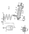
- eine zweite Anlage mit einer Paddelschnecke als zweites Strömungsrohr und
- Fig. 3
- einen Schnitt gemäß Linie A,B in Fig. 2.
- Fig. 1
- a first system with a rotary tube as the second flow tube,
- Fig. 2
- a second system with a paddle screw as a second flow tube and
- Fig. 3
- 3 shows a section along line A, B in FIG. 2.
In Fig. 1 gelangt von einem beheizbaren Behälter 1 eine Polymerlösung über eine Leitung 2 in ein als Entspannungsdüse ausgebildetes Drosselorgan 3, vor welchem noch eine mit einem Absperrventil 4 versehene Inertgasleitung 5 in die Leitung 2 einmündet. Die Entspannungsdüse 3 ist am Eingang eines mit einem Heizmantel 6 versehenen, als stetige Wendel von 20° Neigung ausgebildeten Strömungsrohr 7 angeordnet. In diesem Strömungsrohr 7 wird die Polymerlösung weiter aufkonzentriert. Mit einer mittleren Austrittsgeschwindigkeit von 80 m/s wird dieses Gemisch aus Konzentrat und Brüden senkrecht gegen die Innenwandung 12 eines als Drehrohr ausgebildeten Strömungsrohres 9 geschleudert, dessen Strömungsquerschnitt das 80-fache desjenigen des Strömungsrohres 7 beträgt. Im Drehrohr 9 ist in Drehrichtung etwa 50° hinter der Scheitellinie eine gegensinnig zum Drehrohr 9 angetriebene Messerwelle 10 vorgesehen, deren Messer 11 schraubenlinienförmig gestaltet sind und die Innenwandung 12 des Drehrohres 9 abkratzen. Die Messerwelle 10 besitzt eine Lagerung 13 in der Kopfschale 8 und eine Lagerung 14 in der Fußschale 15. Innerhalb des Drehrohres 9 erreicht das Produkt den gewünschten Konzentrationsgrad. Die Brüden verlassen die Fußschale 15 durch einen Abzug 16 und das Produkt durch einen Auslaß 17.In Fig. 1, a polymer solution passes from a heatable container 1 via a line 2 into a throttle body 3 designed as a relaxation nozzle, in front of which an
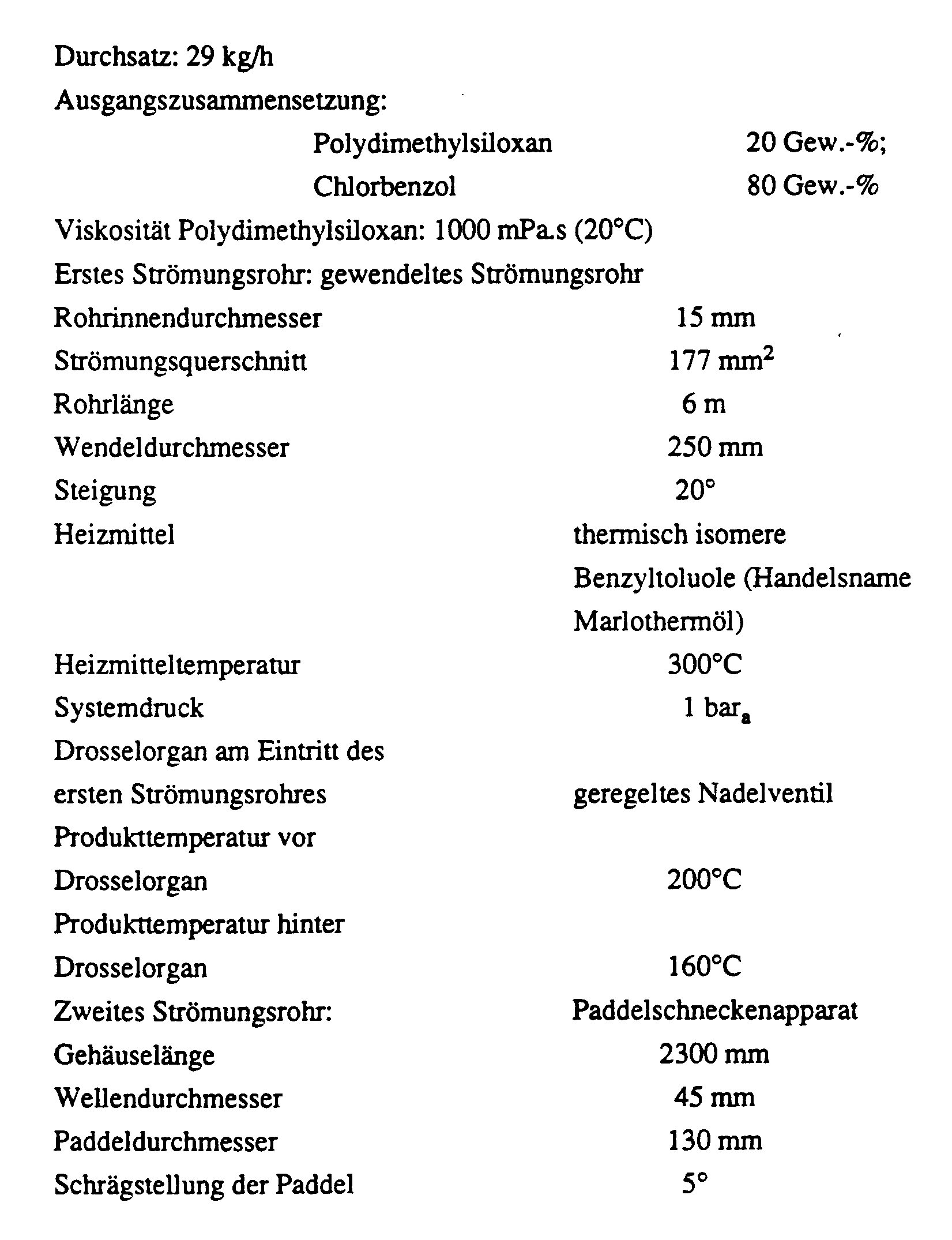
In Fig. 2 und 3 gelangt von einem beheizbaren Behälter 31 eine Polymerlösung über eine Leitung 32 in ein als Entspannungsdüse ausgebildetes Drosselorgan 33, vor welchem noch eine mit einem Absperrventil 34 versehene Fremddampfleitung 35 in die Leitung 32 einmündet. Die Entspannungsdüse 33 ist am Eingang eines mit einem Heizmantel 36 versehenen, als stetige Wendel von 25° Neigung ausgebildeten, ersten Strömungsrohr 37 angeordnet. In diesem Strömungsrohr 37 wird die Polymerlösung weiter aufkonzentriert. Mit einer mittleren Strömungsgeschwindigkeit von 60 m/s gelangt dieses Gemisch aus Konzentrat und Brüden durch einen Einlaßstutzen 38 senkrecht in ein zweites, als Paddelschneckenapparat ausgebildetes Strömungsrohr 39, dessen Querschnitt das 80-fache desjenigen des ersten Strömungsrohres 37 beträgt. Der Paddelschneckenapparat 39 weist ein beheizbares Gehäuse 40 auf, in welchem zwei gegensinnig drehende, miteinander kämmende, mit unter 10° angestellten Paddeln 41 besetzte Wellen 42 und 43 angeordnet sind. Die Paddel 41 schaben die Innenwandung 44 des Gehäuses 40 und sich gegenseitig laufend ab und verhindern auf diese Weise Anbackungen und Verkrustungen. Das auf den gewünschten Grad aufkonzentrierte Produkt wird über einen Auslaß 45 ausgetragen und die Brüden ziehen über einen Abzugsstutzen 46 ab.2 and 3, a polymer solution passes from a

Alle anderen Bedingungen wie im Beispiel 1.
Aufkonzentrierung einer Polydimethylsiloxan-Chlorbenzol-Lösung
Alle anderen Bedingungen wie im Beispiel 1.
Mit Zusatz von 12 kg/h Stickstoff Restlösemittelgehalt: ∼3000 ppm.With the addition of 12 kg / h nitrogen residual solvent content: ∼3000 ppm.
Wie Beispiel 1, jedoch wird als zweites Strömungsrohr anstelle des Paddelschneckenapparates ein Drehrohr verwendet:
Claims (5)
- Continuous method for the concentrating of polymer solutions to a required specification level of residual solvents, wherein the product is heated up under pressure and subsequently expanded in a restricting organ (3, 33) with vapour formation into a heated flow tube (7, 37) and concentrated there, characterised in that in said first flow tube (7, 37) the concentrating is carried out to the greatest possible extent, and that the product is then introduced at an angle into a second heatable flow tube (9, 39) arranged directly downstream, which exhibits self-cleaning elements (10; 11; 41, 42, 43) and at least 50 times the flow area of the first flow tube (7, 37), and is brought to the desired final concentration, and wherein the separation of the vapour flow from the polymer flow does not take place until after the second flow tube (9, 39).
- Method according to claim 1, characterised in that there is used as second flow tube (9) a revolving tube (9) with a self-cleaning cutter spindle (10).
- Method according to claim 1, characterised in that there is used as second flow tube (39) a self-cleaning paddleworm apparatus (39).
- Method according to any one of claims 1 to 3, characterised in that together with the polymer solution inert gas is fed into the first flow tube (7).
- Method according to any one of claims 1 to 3, characterised in that together with the polymer solution foreign vapour is fed into the first flow tube (37).
Applications Claiming Priority (2)
| Application Number | Priority Date | Filing Date | Title |
|---|---|---|---|
| DE4011383A DE4011383A1 (en) | 1990-04-07 | 1990-04-07 | CONTINUOUS METHOD FOR CONCENTRATING POLYMER SOLUTIONS UP TO A REQUIRED SPECIFICATION RANGE OF RESIDUAL SOLVENTS |
| DE4011383 | 1990-04-07 |
Publications (2)
| Publication Number | Publication Date |
|---|---|
| EP0451602A1 EP0451602A1 (en) | 1991-10-16 |
| EP0451602B1 true EP0451602B1 (en) | 1995-02-22 |
Family
ID=6404027
Family Applications (1)
| Application Number | Title | Priority Date | Filing Date |
|---|---|---|---|
| EP91104728A Expired - Lifetime EP0451602B1 (en) | 1990-04-07 | 1991-03-26 | Continuous process for upgrading polymer solutions for a requested specification of residual solvents |
Country Status (4)
| Country | Link |
|---|---|
| US (1) | US5256707A (en) |
| EP (1) | EP0451602B1 (en) |
| CA (1) | CA2039809A1 (en) |
| DE (2) | DE4011383A1 (en) |
Families Citing this family (8)
| Publication number | Priority date | Publication date | Assignee | Title |
|---|---|---|---|---|
| DE4201046A1 (en) * | 1992-01-17 | 1993-07-22 | Bayer Ag | METHOD FOR CLEANING POLYMER SOLUTIONS |
| DE19507594B4 (en) * | 1995-03-04 | 2005-01-13 | Wacker-Chemie Gmbh | Process for the preparation of silicone resins |
| DE19600630A1 (en) | 1996-01-10 | 1997-07-17 | Bayer Ag | Process and device for the continuous evaporation of viscous, sticky solutions and suspensions to dry matter |
| DE19835744A1 (en) * | 1998-08-07 | 2000-02-17 | Bayer Ag | Process for evaporating polymer solutions of thermoplastic polymers |
| FR2788590B1 (en) * | 1999-01-14 | 2001-06-08 | Sirven | HEAT EXCHANGER, ESPECIALLY FOR MANURE PREHEATING |
| DE19918728A1 (en) * | 1999-04-24 | 2000-12-14 | Bayer Ag | Method and device for evaporating polymer solutions of thermoplastic polymers |
| WO2007090768A1 (en) * | 2006-02-09 | 2007-08-16 | Basf Se | Process for obtaining vinyl compounds by evaporation |
| CN113318686A (en) * | 2021-05-21 | 2021-08-31 | 浙江溶力高新材料股份有限公司 | Preparation device and preparation method of high-purity vinyl silicone oil |
Family Cites Families (8)
| Publication number | Priority date | Publication date | Assignee | Title |
|---|---|---|---|---|
| DE274360C (en) * | ||||
| US3395746A (en) * | 1965-12-13 | 1968-08-06 | Union Carbide Corp | Method for devolatilizing liquid polymer compositions |
| DE1667051B2 (en) * | 1967-09-04 | 1976-09-23 | Bayer Ag, 5090 Leverkusen | PROCESS AND DEVICE FOR EVAPORATING IN PARTICULAR VISCOSE LIQUIDS AND FOR EVAPORATING THE PRODUCTS THROUGH REACTIONS |
| DE1921045B2 (en) * | 1969-04-25 | 1976-11-11 | Bayer Ag, 5090 Leverkusen | PROCESS FOR RECOVERING A POLYMER MELT FROM A POLYMER SOLUTION |
| US3834441A (en) * | 1969-04-25 | 1974-09-10 | Bayer Ag | Process for concentrating polymer solutions by evaporation |
| GB1282922A (en) * | 1969-08-11 | 1972-07-26 | Ansafone Ltd | Magnetic tape playback devices |
| DE2724360B2 (en) * | 1977-05-28 | 1981-03-12 | Bayer Ag, 5090 Leverkusen | Process for the production of thermoplastic molding compositions based on vinyl polymers |
| NL8203281A (en) * | 1982-08-21 | 1984-03-16 | Stamicarbon | DEVICE AND METHOD FOR WINNING POLYMER FROM A SOLUTION. |
-
1990
- 1990-04-07 DE DE4011383A patent/DE4011383A1/en not_active Withdrawn
-
1991
- 1991-03-22 US US07/673,731 patent/US5256707A/en not_active Expired - Fee Related
- 1991-03-26 EP EP91104728A patent/EP0451602B1/en not_active Expired - Lifetime
- 1991-03-26 DE DE59104645T patent/DE59104645D1/en not_active Expired - Fee Related
- 1991-04-04 CA CA002039809A patent/CA2039809A1/en not_active Abandoned
Also Published As
| Publication number | Publication date |
|---|---|
| DE59104645D1 (en) | 1995-03-30 |
| DE4011383A1 (en) | 1991-10-10 |
| EP0451602A1 (en) | 1991-10-16 |
| CA2039809A1 (en) | 1991-10-08 |
| US5256707A (en) | 1993-10-26 |
Similar Documents
| Publication | Publication Date | Title |
|---|---|---|
| EP2180987B1 (en) | Method for the production of polyester granules low in hydrolysis made of high-viscosity polyester melts, and device for the production of the polyester granules, and polyester granules low in hydrolysis | |
| EP0516936A1 (en) | Method and device for preparing or making plastic materials | |
| EP4079385A1 (en) | Thin film treatment device | |
| DE3711328C1 (en) | Degassing device for screw extruders | |
| EP0451602B1 (en) | Continuous process for upgrading polymer solutions for a requested specification of residual solvents | |
| DE2400661A1 (en) | IMPROVED FALL FLOW EVAPORATION PROCESS | |
| AT411429B (en) | Extraction of impurities from thinly-coated fluid film involves treating its surface with liquid carbon dioxide whilst continuously replenishing film thickness | |
| DE69822228T2 (en) | DEVICE FOR TREATING REUSABLE PLASTIC MATERIALS | |
| DE10237281A1 (en) | Device for the continuous extraction of extract substances from plants | |
| EP0451601B1 (en) | Continuous process for the separation of solutions and suspensions in a flowable solid and a distillate extensively free of solids | |
| EP3564005B1 (en) | Mixing and kneading device, and its use | |
| DE1907586A1 (en) | Reactor for a device for the continuous production of chromic anhydride (Dhromtioxyd) | |
| CH643149A5 (en) | METHOD AND DEVICE FOR CONTINUOUS THERMAL TREATMENT OF PUMPABLE SUBSTANCES IN A THIN LAYER. | |
| DE3030662A1 (en) | METHOD FOR DRYING PUMPABLE SUSPENSIONS | |
| EP3777987A1 (en) | Device for the thermal treatment of material, particularly for thermal separation of material components contained in the material | |
| EP1094873B1 (en) | Method for isolating polymers from solutions | |
| EP1477223B1 (en) | Large volume reactor with a plurality of process chambers | |
| DE69733795T2 (en) | Method for thickening liquid mixtures | |
| WO2016078994A1 (en) | Method of processing and/or recovering and/or reutilizing residues, especially from refinery processes | |
| DE2908352A1 (en) | METHOD FOR SEPARATING THE INDIVIDUAL PHASE CURRENTS OF A MULTI-PHASE CURRENT | |
| DE1495665B2 (en) | PROCESS AND DEVICE FOR CONTINUOUS FLOW RATE OF MELT IN THE MANUFACTURING OF POLYCONDENSATION PRODUCTS | |
| CH642557A5 (en) | DC EVAPORATOR. | |
| AT392919B (en) | METHOD AND DEVICE FOR TREATING TREATMENT OR -REACTION | |
| DE19630389A1 (en) | Method and device for removing volatile components from highly viscous solutions or suspensions | |
| DE1964946B2 (en) | DEVICE FOR CONCENTRATING A SOLUTION OR SUSPENSION UNTIL PLASTIC |
Legal Events
| Date | Code | Title | Description |
|---|---|---|---|
| PUAI | Public reference made under article 153(3) epc to a published international application that has entered the european phase |
Free format text: ORIGINAL CODE: 0009012 |
|
| AK | Designated contracting states |
Kind code of ref document: A1 Designated state(s): BE CH DE ES FR GB IT LI NL |
|
| 17P | Request for examination filed |
Effective date: 19911111 |
|
| 17Q | First examination report despatched |
Effective date: 19940714 |
|
| GRAA | (expected) grant |
Free format text: ORIGINAL CODE: 0009210 |
|
| PGFP | Annual fee paid to national office [announced via postgrant information from national office to epo] |
Ref country code: DE Payment date: 19950214 Year of fee payment: 5 |
|
| AK | Designated contracting states |
Kind code of ref document: B1 Designated state(s): BE CH DE ES FR GB IT LI NL |
|
| RBV | Designated contracting states (corrected) |
Designated state(s): DE |
|
| REF | Corresponds to: |
Ref document number: 59104645 Country of ref document: DE Date of ref document: 19950330 |
|
| NLXE | Nl: other communications concerning ep-patents (part 3 heading xe) |
Free format text: PAT.BUL.06/95 PATENTNUMBER 0451602 SHOULD BE DELETED |
|
| PLBE | No opposition filed within time limit |
Free format text: ORIGINAL CODE: 0009261 |
|
| STAA | Information on the status of an ep patent application or granted ep patent |
Free format text: STATUS: NO OPPOSITION FILED WITHIN TIME LIMIT |
|
| 26N | No opposition filed | ||
| PG25 | Lapsed in a contracting state [announced via postgrant information from national office to epo] |
Ref country code: DE Effective date: 19961203 |