EP0451040A1 - Closed system intravenous catheter - Google Patents
Closed system intravenous catheter Download PDFInfo
- Publication number
- EP0451040A1 EP0451040A1 EP91400879A EP91400879A EP0451040A1 EP 0451040 A1 EP0451040 A1 EP 0451040A1 EP 91400879 A EP91400879 A EP 91400879A EP 91400879 A EP91400879 A EP 91400879A EP 0451040 A1 EP0451040 A1 EP 0451040A1
- Authority
- EP
- European Patent Office
- Prior art keywords
- stylet
- catheter
- skin
- fluid
- penetrating
- Prior art date
- Legal status (The legal status is an assumption and is not a legal conclusion. Google has not performed a legal analysis and makes no representation as to the accuracy of the status listed.)
- Withdrawn
Links
Images

Classifications
-
- A—HUMAN NECESSITIES
- A61—MEDICAL OR VETERINARY SCIENCE; HYGIENE
- A61M—DEVICES FOR INTRODUCING MEDIA INTO, OR ONTO, THE BODY; DEVICES FOR TRANSDUCING BODY MEDIA OR FOR TAKING MEDIA FROM THE BODY; DEVICES FOR PRODUCING OR ENDING SLEEP OR STUPOR
- A61M25/00—Catheters; Hollow probes
- A61M25/01—Introducing, guiding, advancing, emplacing or holding catheters
- A61M25/06—Body-piercing guide needles or the like
- A61M25/0606—"Over-the-needle" catheter assemblies, e.g. I.V. catheters
-
- A—HUMAN NECESSITIES
- A61—MEDICAL OR VETERINARY SCIENCE; HYGIENE
- A61M—DEVICES FOR INTRODUCING MEDIA INTO, OR ONTO, THE BODY; DEVICES FOR TRANSDUCING BODY MEDIA OR FOR TAKING MEDIA FROM THE BODY; DEVICES FOR PRODUCING OR ENDING SLEEP OR STUPOR
- A61M25/00—Catheters; Hollow probes
-
- A—HUMAN NECESSITIES
- A61—MEDICAL OR VETERINARY SCIENCE; HYGIENE
- A61M—DEVICES FOR INTRODUCING MEDIA INTO, OR ONTO, THE BODY; DEVICES FOR TRANSDUCING BODY MEDIA OR FOR TAKING MEDIA FROM THE BODY; DEVICES FOR PRODUCING OR ENDING SLEEP OR STUPOR
- A61M39/00—Tubes, tube connectors, tube couplings, valves, access sites or the like, specially adapted for medical use
- A61M39/10—Tube connectors; Tube couplings
- A61M39/14—Tube connectors; Tube couplings for connecting tubes having sealed ends
-
- A—HUMAN NECESSITIES
- A61—MEDICAL OR VETERINARY SCIENCE; HYGIENE
- A61M—DEVICES FOR INTRODUCING MEDIA INTO, OR ONTO, THE BODY; DEVICES FOR TRANSDUCING BODY MEDIA OR FOR TAKING MEDIA FROM THE BODY; DEVICES FOR PRODUCING OR ENDING SLEEP OR STUPOR
- A61M39/00—Tubes, tube connectors, tube couplings, valves, access sites or the like, specially adapted for medical use
- A61M39/10—Tube connectors; Tube couplings
- A61M2039/1033—Swivel nut connectors, e.g. threaded connectors, bayonet-connectors
-
- A—HUMAN NECESSITIES
- A61—MEDICAL OR VETERINARY SCIENCE; HYGIENE
- A61M—DEVICES FOR INTRODUCING MEDIA INTO, OR ONTO, THE BODY; DEVICES FOR TRANSDUCING BODY MEDIA OR FOR TAKING MEDIA FROM THE BODY; DEVICES FOR PRODUCING OR ENDING SLEEP OR STUPOR
- A61M39/00—Tubes, tube connectors, tube couplings, valves, access sites or the like, specially adapted for medical use
- A61M39/10—Tube connectors; Tube couplings
- A61M2039/1066—Tube connectors; Tube couplings having protection means, e.g. sliding sleeve to protect connector itself, shrouds to protect a needle present in the connector, protective housing, isolating sheath
Definitions
- the present invention relates generally to catheters used to administer intravenous, arterial or central venous fluids, and more particularly but not by way of limitation, to an improved closed system angiocatheter.
- Catheters are used to administer intravenous, arterial or central venous fluids to a patient.
- One of the most commonly employed catheters is the angiocatheter which comprises a tapered catheter having a fluid-flow passageway extending therethrough and a skin-penetrating stylet.
- the skin-penetrating stylet is provided with a sharpened puncture tip and an observation chamber having a flashpoint cavity therein.
- the puncture tip extends beyond the catheter so that the puncture tip can puncture the skin and vein prior to placement of the catheter into the vein.
- blood can flow through the skin-penetrating stylet and into the flashpoint cavity to indicate to the health care worker that the angiocatheter is properly positioned within the vein. Further confirmation that the angiocatheter has been properly positioned in the vein can be achieved by partially “backing off” or removing the skin-penetrating stylet so that blood flow can continue through the fluid- flow passageway of the catheter.
- intravenous tubing can be connected to the catheter so that intravenous fluids can be administered to the patient.
- the health care worker places a thumb against the vein to tamponade the vein and thereby restrict blood flow into the catheter.
- an improved intravenous catheter which, when properly positioned within a vein, provides a closed system catheter. That is, once the catheter is implanied in a vein, the catheter is effectively self- sealing and the catheter not only prevents leakage of blood therethrough, but also effectively closes off the internal portion of the catheter to the external surrounding environment so that germs and viruses cannot enter the patient's bloodstream through the implanted catheter.
- the closed system intravenous catheter of the present invention comprises a catheter having a tapered portion, a hub portion and a fluid-flow passageway extending therethrough.
- a fluid-impermeable elastomeric gasket member is disposed within the hub portion of the catheter for sealing the hub portion and the fluid-flow passageway of the catheter.
- a skin-penetrating stylet of a stylet assembly extends through the elastomeric gasket member and the fluid-flow passageway of the catheter so that a puncture tip on a proximal end of the skin-penetrating stylet extends outwardly from the tapered portion of the catheter.
- the puncture tip of the skin-penetrating stylet permits one to produce a puncture site in the patient's skin so that the tapered portion of the catheter can be positioned in a vein without great discomfort to the patient.
- the stylet assembly is provided with an observation chamber connected to a distal end of the skin-penetrating stylet.
- the observation chamber which defines a flashpoint cavity, is connected to an air-permeable, liquid-impermeable vent assembly so that the flow of blood into the flashpoint cavity can be observed and effectively controlled.
- the vent assembly not only permits one to control the flow of blood into the flashpoint cavity, but also permits one to operably connect auxiliary equipment, such as a blood sampling device, to the catheter without leakage of blood.
- the vent assembly comprises an air-permeable, liquid-impermeable frit supported on the observation chamber of the stylet assembly and a vent stylet connected to the observation chamber of the stylet assembly so as to openly communicate with the flashpoint cavity.
- a fluid-impermeable elastomeric cover member is connected to the frit such that the cover member is positionable over the vent stylet.
- the air-permeable, liquid-impermeable frit cooperates with the vent stylet and the elastomeric cover member so that blood is permitted to flow into the flashpoint cavity of the observation chamber, while preventing the flow of blood from the flashpoint cavity through the vent stylet until such time as auxiliary equipment has been properly connected to the observation chamber of the stylet assembly.
- the fluid-impermeable elastomeric cover member is compressed by the auxiliary equipment so that a puncture tip of the vent stylet penetrates through the elastomeric cover member and fluid communication is established between the stylet assembly and the auxiliary equipment via the vent stylet. Because of the resilient nature of the fluid-impermeable elastomeric cover member, when the auxiliary equipment is disengaged from the vent stylet, the cover member returns to a non-compressed condition and effectively seals the vent stylet so that the fluid-tight seal is reestablished.
- a closure member or cap is positionable over the vent assembly so as to effectively encapsulate the vent stylet.
- a protective sheath is advantageously incorporated into the stylet assembly of the angiocatheter so as to effectively encapsulate the puncture tip of the skin-penetrating stylet.
- An object of the present invention is to provide an improved intravenous catheter.
- Another object of the present invention while achieving the before stated object, is to provide a closed system intravenous catheter which prevents undesired leakage of blood therethrough and which prevents exposure of health care workers to potentially infectious blood.
- Another object of the present invention while achieving the before stated objects, is to provide a multi-purpose closed system intravenous catheter which is easy to use and which reduces the number of puncture sites required in the treatment of a patient.
- Yet another object of the present invention is to provide an improved closed system catheter which is simple in construction and economical to manufacture.
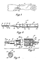
- FIG. 1 is a pictorial illustration of an angiocatheter of the present invention disposed within a vein of a patient's arm.
- FIG. 2 is an enlarged side view, partially in cross section, of the angiocatheter of the present invention having a closure cap supported on an observation chamber so as to be disposed in a covering position over a vent assembly of the angiocatheter.
- FIG. 3 is an enlarged side view, partially in cross section, of the catheter of the angiocatheter of the present invention illustrating auxiliary equipment positioned for attachment to the catheter.
- FIG. 4 is an enlarged view of the catheter of the angiocatheter of the present invention, taken along the line 4-4 of FIG. 3.
- FIG. 5 is an enlarged side view, partially in cross section, of the angiocatheter of the present invention illustrating a vent assembly for the observation chamber of the stylet assembly wherein the closure cap is disposed in a covering position over the vent assembly.
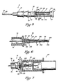
- FIG. 6 is an enlarged, fragmental side view, partially in cross section, of the vent assembly of the angiocatheter of the present invention wherein an elastomeric stylet covering member of the vent assembly is disposed over a vent stylet.
- FIG. 7 is an enlarged, fragmental side view, partially in cross section, of a blood sampling device operably connected to the angiocatheter of the present invention.
- FIG. 8 is an enlarged, fragmental side view, partially in cross section of a protective sheath for the skin-penetrating stylet of the angiocatheter of the present invention wherein the protective sheath is in a retracted, compressed position when the skin-penetrating stylet is disposed within the catheter.
- FIG. 9 is an enlarged, fragmental side view, partially in cross section of the protective sheath for the skin-penetrating stylet of the angiocatheter of the present invention wherein the protective sheath is in an extended skin-penetrating stylet covering position.
- FIG. 10 is an enlarged, fragmental side view, partially in cross section of a second embodiment of a protective sheath of the skin-penetrating stylet of the angiocatheter of the present invention.
- an improved angiocatheter 10 of the present invention is illustrated positioned within a vein 12 in a patient's arm 14.
- the angiocatheter 10 permits one to produce a puncture site 16 in a patient's skin 18 and the underlying vein 12 so that a tapered proximal end portion 20 of a'catheter 22 can be positioned within the vein 12 without great discomfort to the patient, while at the same time reducing slippage and coring.
- Auxiliary equipment such as a Vacutainer® brand blood sampling device 24 (FIG. 7), can be connected to the angiocatheter 10 without the need of puncturing the patient's skin a second time to produce a second puncture site, or a standard intravenous needle by be used to connect intravenous fluid tubing 26 (FIG. 3) to the catheter 22 so that intravenous fluids can be administered to the patient via the catheter 22.
- a standard intravenous needle by be used to connect intravenous fluid tubing 26 (FIG. 3) to the catheter 22 so that intravenous fluids can be administered to the patient via the catheter 22.
- the unique design of the catheter 22 also permits one to administer repeated injections using an injection needle connected to a syringe.
- closed system catheter as used herein is understood to mean that once the catheter 22 is properly implanted in the vein 12 a fluid-flow passageway 28 which extends through the catheter 22 (FIG. 3) is effectively self-sealing so as to prevent leakage of blood therethrough without the requirement of an external cap member.
- the fluid-flow passageway 28 of the catheter 22 is effectively sealed to the surrounding environment so that air, germs and viruses cannot enter the patient's blood- stream through the fluid-flow passageway 28 of the implanted catheter 22.
- the angiocatheter 10 comprises the catheter 22, a resilient, fluid-impermeable gasket member 30 and a stylet assembly 32.
- the resilient gasket member 30, which is fabricated of a substantially fluid-impermeable elastomeric material, is supported with a cavity 34 defined by a hub 36 of the catheter 22 so that the gasket member 30 effectively seals the fluid-flow passageway 28 of the catheter 22 to both air and liquid.
- a skin-penetrating stylet 37 of the stylet assembly 32 is slidably disposed within the fluid-flow passageway 28 of the catheter 22 so as to penetrate the resilient gasket member 30.
- a puncture tip 38 of the skin-penetrating stylet 37 extends outwardly from the tapered proximal end portion 20 of the catheter 22 substantially as shown in FIG. 2.
- the puncture tip 38 of the skin-penetrating stylet 37 punctures the puncture site 16 on the patient's skin 18, and the underlying vein 12, so that the tapered proximal end portion 20 of the catheter 22 can be positioned within the vein 12.
- the resilient gasket member 30 effectively reseals the place of penetration of the skin-penetrating stylet 37 in the resilient gasket member 30 so as to provide a fluid-impermeable seal for the fluid-flow passageway 28 of the catheter 22.
- the resilient gasket member 30 prevents blood leakage through the fluid-flow passageway 28 of the catheter 22, while at the same time closing off the fluid-flow passageway 28 from contact with the outward surrounding environment or atmosphere.
- the catheter 22 comprises the hub 36 and a tapered body member 40.
- the hub 36 and the tapered body member 40 can be fabricated of any suitable polymeric material; and the hub 36 and the tapered body member are desirably of unitary construction.
- the tapered body member 40 is an elongated member having the tapered proximal end portion 20, a distal end portion 42 and a fluid-flow bore 44 extending therethrough.
- the hub 36 is supported by the distal end portion 42 of the tapered body member 40 such that the cavity 34 of the hub 36 openly communicates with the fluid-flow bore 44 of the tapered body member 40.
- the cavity 34 of the hub 36 and the fluid-flow bore 44 of the tapered body member 40 cooperate to define the fluid-flow passageway 28 of the catheter 22.
- the hub 36 of the catheter 22 is further provided with a pair of oppositely disposed, outwardly extending tab members 46, 48 adapted to operably engage mating threads 50 disposed within an open first end 52 of an intravenous fluid tubing connector 54 (see FIG. 3).
- the connector 54 a substantially cylindrical-shaped member, in addition to the open first end 52, is characterized as having an opposed second end 56.
- the opposed second end 56 is provided with a centrally disposed aperture 58 adapted to receive an elongated, cylindrical-shaped tubular coupling member 60.
- the coupling member 60 (which is slidably disposed through the aperture 58) is provided with a first end 62 and an opposed second end 64.
- the first end 62 of the coupling member 60 extends inwardly into the connector 54; and the opposed second end 64 of the coupling member 60 is positioned exterior the connector 54 substantially as shown in FIG. 3.
- the coupling member 60 is provided with a pair of spatially disposed stop members 66 and 68, each of which has a diameter greater than the diameter of the aperture 58. As shown in FIG.
- the stop member 66 is connected to the coupling member 60 so as to be disposed within a hollow interior portion 70 of the connector 54; and the stop member 68 is connected to the coupling member 60 so as to be disposed exterior the connector 54.
- an intravenous tubing stylet or needle 72 is connected to the first end 62 of the coupling member 60; and the intravenous fluid tubing 26 is connected to the opposed second end 64 of the coupling member 60.
- fluid communication is established between the intravenous tubing stylet or needle 72 and the intravenous fluid tubing 26.
- the intravenous tubing stylet 72 in order to establish fluid communication between the intravenous tubing stylet 72 and the fluid-flow passageway 28 of the catheter 22, the intravenous tubing stylet 72 must have a sufficient length so that when the connector 54 is threadably connected to the hub 36 of the catheter 22, the intravenous tubing stylet 72 penetrates the resilient gasket member 30 and openly communicates with the fluid-flow passageway 28 of the catheter 22.
- the stylet assembly 32 in addition to the skin-penetrating stylet 37, comprises an observation chamber 74 which defines a flashpoint cavity 76 therein.
- the flashpoint cavity 76 is in fluid communication with a fluid-flow bore 78 of the skin-penetrating stylet 37 so that blood flow through the skin-penetrating stylet 37 via the bore 78 can be observed in the flashpoint cavity 76.
- a vent assembly 80 is connected to and supported by the observation chamber 74 so that the flow of blood into the flashpoint cavity 76 cannot only be observed therein, but can be effectively controlled by the vent assembly 80.
- vent assembly 80 in addition to permitting one to control the flow of blood into the flashpoint cavity 76, also permits one to operably connect auxiliary equipment, such as the blood sampling device 24 (see Fig. 7) to the stylete assembly 32, and thus the catheter 22 without leakage of blood therethrough.
- auxiliary equipment such as the blood sampling device 24 (see Fig. 7)
- the vent assembly 80 and its interconnection with the flashpoint cavity 76 of the observation chamber 74 is illustrated.
- the vent assembly 80 comprises an air-permeable, liquid-impermeable frit member 82 supported on a distal end 84 of the observation chamber 74.
- the distal end portion 84 of the observation chamber 74 comprises an externally threaded post member 86 adapted to matingly engage a female member 88 having internally disposed threads 90 of an auxiliary piece of equipment, such as the blood sampling device 24.
- the threaded post member 86 is provided with a centrally disposed bore 92 extending therethrough, the bore 92 adapted to receive a vent stylet 94 such that one end 96 of the vent stylet 94 extends inwardly into the observation chamber 74 and an opposed second or distal end 98 thereof extends outwardly from the threaded post member 86 of the observation chamber 74.
- the vent stylet 94 openly communicates with the flashpoint cavity 76 defined by the observation chamber 74 via a fluid-flow passage bore 99 of the vent stylet 94.
- the vent assembly 80 further comprises a fluid-impermeable elastomeric cover member 100 supported by the frit member 82 such that a fluid-tight seal is formed therebetween.
- the cover member 100 is a tubular member and is positionable over the vent stylet 94 substantially shown.
- the cover member 100 is characterzed as having an open first end portion 102 and a closed second end portion 104.
- the first end portion 102 is provided with a skirt 105 adapted to frictionally engage a portion of the frit member 82 such that the fluid-tight seal is formed therebetween.
- the frit member 82 cooperates with the vent stylet 94 and the elastomeric cover member 100 so that blood is permitted to flow into the flashpoint cavity 76 of the observation chamber 74 via the skin-penetrating stylet 37 when the skin-penetrating stylet 37 and the catheter 22 are properly positioned within a vein; while preventing the flow of blood from the flashpoint cavity 76 through the vent stylet 94 until such time as auxiliary equipment, such as the blood sampling device 24, has been properly connected to the threaded post member 86 of the stylet assembly 32.
- the cover member 100 is provided with a length such that when the cover member 100 is positioned over the vent stylet 94, the closed second end 104 thereof is disposed substantially adjacent a puncture tip 106 of the vent stylet 94 but in a non-blocking relationship therewith so that fluid flow can be maintained through the fluid-flow passageway 99 of the vent stylet 94.
- the cover member 100 is provided with a length such that when the cover member 100 is positioned over the vent stylet 94, the closed second end 104 thereof is disposed substantially adjacent a puncture tip 106 of the vent stylet 94 but in a non-blocking relationship therewith so that fluid flow can be maintained through the fluid-flow passageway 99 of the vent stylet 94.
- the air expelled from the vent stylet 94 travels along a passageway 108 formed between the vent stylet 94 and the cover member 100 so as to be directed to the frit member 82 where the air, upon passage therethrough, is discharged to the surrounding environment.
- cover member 100 has been depicted as being connectable to the frit member 82 via the skirt 105 formed on the first end portion 102 of the cover member 100
- any suitable means for connecting the first end portion 102 of the cove member 100 to the frit member 82 so as to form a fluid-tight seal therebetween can be employed.
- a suitable adhesive exercising care to insure that the frit maintains sufficient porosity for the passage of air therethrough, an O-ring, a clamp, or other similar connecting devices.
- the vent assembly 80 further comprises a closure member 110 positionable over the vent stylet 94 substantially as shown in FIGS. 1, 2 and 5.
- the closure member 110 is a cylindrical-shaped member having a first end 112, a closed second end 114 and a cavity 116 openly communicating with the first end 112.
- the closure member 110 is desirably provided with at least one air port 117 substantially as shown in FIG.
- the closure member 110 can be disposed in a covering position over the vent stylet 94, the elastomeric cover member 100 and the frit member 82 so that the first end 112 supportingly engages the observation chamber 74.
- the closure member 110 frictionally engages the threaded post member 86 so that the cover member 110 is secured in a covering position, while permitting the closure member 110 to be readily removed when access is desired to the vent stylet 94.
- auxiliary equipment such as the blood sampling device 24 (FIG. 7)
- the closure member 110 is removed so that the vent stylet 94 and the cover member 100 are accessible.
- the auxiliary equipment such as the blood sampling device 24, is provided with a throat portion 118 having internally disposed threads 120.
- the throat portion 118 is positioned over the vent stylet 94, and the auxiliary equipment is threadably connected to the threaded post member 86 of the observation chamber 74, the throat portion 118 of the device 24 is disposed in a covering position over the frit member 82.
- the vent stylet 94 is forced to penetrate the closed second end 104 of the covering member 100 and thereby establish fluid communication with the auxiliary equipment. That is, the blood sampling device 24 compresses the cover member 100 so as to permit penetration of the puncture tip 106 of the vent stylet 94 therethrough, and thereby allows blood to flow from the catheter to the blood sampling device 24.
- the cover member 100 Because of the elastic properties of the cover member 100, when the blood sampling device 24 is removed from the angiocatheter 10, the cover member 100 returns to its non-compressed condition and once again serves to restrict liquid flow through the vent stylet 94. Further, the elastomeric characteristics of the cover member 100 permit the point of puncture through the closed second 104 thereof to reseal itself so that an effective fluid-impermeable seal is again achieved.
- the frit member 82 of the vent assembly 80 is, as previously stated, air-permeable and liquid-impermeable.
- the frit member 82 can be fabricated of any suitable material having those 'required properties.
- the frit member 82 can be fabricated of a ceramic material, non-wicking fibrous material, compressed fibrous polymeric material and the like.
- the angiocatheter 10 further comprises a retractable sheath 130 connected to and supported by the observation chamber 74 of the stylet assembly 32 so as to minimize exposure of a health care worker to inadvertent puncture by the puncture tip 38 of the skin-penetrating stylet 37 when the skin-penetrating stylet 37 is removed from the passageway 28 of the catheter 22.
- the retractable sheath 130 comprises an elongated body member 132 having a longitudinally extending passageway 134 adapted to receive the skin-penetrating stylet 37 of the stylet assembly 32; and the retractable sheath 130 is selectively movable between a retracted position (FIG. 8) and an extended position (FIG. 9).
- the body member 132 is preferably fabricated of a polymeric material having sufficient rigidity to maintain the body member 132 of the retractable sheath 130 in a substantially rigid, extended position, while at the same time permitting the body member 132 of the retractable sheath 130 to be slidably moved to the retracted position along the skin-penetrating stylet 37 when the skin-penetrating stylet 37 of the stylet assembly 32 is slidably positioned in the fluid-flow passageway 28 of the catheter 22.
- the polymeric material desirably possesses sufficient memory propercies so that the sheath 130 returns to its extended position when compressive forces maintaining the sheath 130 in its retracted position are removed.
- the body member 132 of the retractable sheath 130 is provided with a length greater than the length of the skin-penetrating stylet 37 when same is in the extended position (see FIG. 9) so that the puncture tip 38 of the skin-penetrating stylet 37, as well as the skin-penetrating stylet 37, are completely surrounded by the body member 132 of the retractable sheath 130.
- the body member 132 of the retractable sheath can be provided with a plurality of accordian-like pleats 136 formed along its length.
- the gasket member 30 exerts a force on an adjacently disposed end 138 of the body member 132 and continued movement of the skin- penetrating stylet 37 through the passageway 28 of the catheter 22 results in compression and folding of the accordian-like pleats 136 substantially as shown in FIG. 8.
- the reduced force applied to the stylet assembly 32 during withdrawal relaxes or releases the compressive tension on the adjacently disposed end 138 of the body member 130 caused by the gasket member 30 so that the body member 132 of the sheath 130 is allowed to return to its extended position as the skin-penetrating stylet 37 is withdrawn from the fluid-flow passageway 28 of the catheter 22.
- the body member 132 of the sheath 130 is positioned in its covering position relative to the skin-penetrating stylet 37 substantially as shown in FIG. 9.
- sheath 130 has been depicted as an elongated body member having accordian-like pleats formed along its length, it should be understood that any other suitable means can be employed for providing a protective cover for the skin-penetrating stylet 37 when same is removed from the fluid passageway 28 of the catheter 22, such as a telescoping sheath and the like.
- the sheath 130 is illustrated as having a compression spring 140 embedded within the body member 132 so as to enhance the movement of the body member 132 to its extended stylet covering position (FIG. 9) when the skin-penetrating stylet 37 is removed from the fluid passageway 28 of the catheter 22.
- closed system angiocatheter 10 of the present invention represents an advancement in the state of the art for numerous reasons, including, but not limited to:
Landscapes
- Health & Medical Sciences (AREA)
- Life Sciences & Earth Sciences (AREA)
- Heart & Thoracic Surgery (AREA)
- Hematology (AREA)
- Anesthesiology (AREA)
- Biomedical Technology (AREA)
- Engineering & Computer Science (AREA)
- Pulmonology (AREA)
- Animal Behavior & Ethology (AREA)
- General Health & Medical Sciences (AREA)
- Public Health (AREA)
- Veterinary Medicine (AREA)
- Biophysics (AREA)
- Infusion, Injection, And Reservoir Apparatuses (AREA)
- Media Introduction/Drainage Providing Device (AREA)
Applications Claiming Priority (2)
| Application Number | Priority Date | Filing Date | Title |
|---|---|---|---|
| US50413390A | 1990-04-03 | 1990-04-03 | |
| US504133 | 1990-04-03 |
Publications (1)
| Publication Number | Publication Date |
|---|---|
| EP0451040A1 true EP0451040A1 (en) | 1991-10-09 |
Family
ID=24004985
Family Applications (1)
| Application Number | Title | Priority Date | Filing Date |
|---|---|---|---|
| EP91400879A Withdrawn EP0451040A1 (en) | 1990-04-03 | 1991-03-29 | Closed system intravenous catheter |
Country Status (7)
| Country | Link |
|---|---|
| EP (1) | EP0451040A1 (ko) |
| JP (1) | JPH04224768A (ko) |
| KR (1) | KR910018046A (ko) |
| AU (1) | AU7394791A (ko) |
| CA (1) | CA2039390A1 (ko) |
| IE (1) | IE911031A1 (ko) |
| IL (1) | IL97752A0 (ko) |
Cited By (55)
| Publication number | Priority date | Publication date | Assignee | Title |
|---|---|---|---|---|
| EP0567321A2 (en) * | 1992-04-21 | 1993-10-27 | Critikon, Inc. | Intravenous catheter with needle guard |
| EP0615768A2 (en) * | 1993-01-21 | 1994-09-21 | Robert E. Fischell | Device for subcutaneous medication delivery |
| WO2001052617A2 (en) * | 2000-01-18 | 2001-07-26 | Sterling Medivations, Inc. | Subcutaneous injection set for use with a reservoir that has a septum |
| US6685674B2 (en) | 2001-03-04 | 2004-02-03 | Sterling Medivations, Inc. | Infusion hub assembly and fluid line disconnect system |
| US20080086085A1 (en) * | 2004-05-03 | 2008-04-10 | Leroy Brown | Blood drawing device with flash detection |
| US7585287B2 (en) | 2004-06-16 | 2009-09-08 | Smiths Medical Md, Inc. | Device and method for insertion of a cannula of an infusion device |
| US7648494B2 (en) | 2004-03-26 | 2010-01-19 | Unomedical A/S | Infusion set and injector device for infusion set |
| US7699807B2 (en) | 2003-11-10 | 2010-04-20 | Smiths Medical Asd, Inc. | Device and method for insertion of a cannula of an infusion device |
| US7699808B2 (en) | 2003-11-10 | 2010-04-20 | Smiths Medical Asd, Inc. | Subcutaneous infusion device and method |
| US7731691B2 (en) | 2003-11-10 | 2010-06-08 | Smiths Medical Asd, Inc. | Subcutaneous infusion device and device for insertion of a cannula of an infusion device and method |
| US7736337B2 (en) * | 2006-02-16 | 2010-06-15 | Smiths Medical, Asd, Inc. | Sealing catheter hub attachment |
| US7744570B2 (en) | 2003-11-18 | 2010-06-29 | Icu Medical, Inc. | Infusion set |
| US7850658B2 (en) | 2003-11-10 | 2010-12-14 | Smiths Medical Asd, Inc. | Subcutaneous infusion device and method including release feature for adhesive portion |
| US7879010B2 (en) | 2001-04-06 | 2011-02-01 | Roche Diagnostics International Ag | Infusion set |
| US7892216B2 (en) | 2006-02-07 | 2011-02-22 | Icu Medical, Inc. | Infusion set |
| US7985199B2 (en) | 2005-03-17 | 2011-07-26 | Unomedical A/S | Gateway system |
| WO2011094397A1 (en) * | 2010-02-01 | 2011-08-04 | William Paul Spurbeck | Angiocatheter device with improved safety features |
| US7993306B2 (en) | 2006-10-31 | 2011-08-09 | Smiths Medical Asd, Inc. | Subcutaneous infusion device and method including tapered cannula |
| US8012126B2 (en) | 2006-10-31 | 2011-09-06 | Unomedical A/S | Infusion set |
| US8062250B2 (en) | 2004-08-10 | 2011-11-22 | Unomedical A/S | Cannula device |
| US8066678B2 (en) | 2001-12-17 | 2011-11-29 | Bard Access Systems, Inc. | Safety needle with collapsible sheath |
| US8152771B2 (en) | 2001-09-27 | 2012-04-10 | Unomedical A/S | Injector device for placing a subcutaneous infusion set |
| US8231582B2 (en) | 2008-12-11 | 2012-07-31 | Bard Access Systems, Inc. | Device for removing a Huber needle from a patient |
| US8246588B2 (en) | 2007-07-18 | 2012-08-21 | Unomedical A/S | Insertion device with pivoting action |
| US8303549B2 (en) | 2005-12-23 | 2012-11-06 | Unomedical A/S | Injection device |
| US8430850B2 (en) | 2007-07-03 | 2013-04-30 | Unomedical A/S | Inserter having bistable equilibrium states |
| US8439838B2 (en) | 2006-06-07 | 2013-05-14 | Unomedical A/S | Inserter for transcutaneous sensor |
| US8486003B2 (en) | 2007-07-10 | 2013-07-16 | Unomedical A/S | Inserter having two springs |
| US8562567B2 (en) | 2009-07-30 | 2013-10-22 | Unomedical A/S | Inserter device with horizontal moving part |
| US8790311B2 (en) | 2006-06-09 | 2014-07-29 | Unomedical A/S | Mounting pad |
| US8795309B2 (en) | 2009-07-29 | 2014-08-05 | Smiths Medical Asd, Inc. | Device for insertion of a cannula of an infusion device and method |
| US8852154B2 (en) | 2004-02-26 | 2014-10-07 | C. R. Bard, Inc. | Huber needle safety enclosure |
| US8945057B2 (en) | 2006-08-02 | 2015-02-03 | Unomedical A/S | Cannula and delivery device |
| WO2015039153A1 (de) | 2013-09-17 | 2015-03-26 | Greiner Bio-One Gmbh | Abnahmeeinheit für körperflüssigkeiten, insbesondere blut |
| US9186480B2 (en) | 2007-06-20 | 2015-11-17 | Unomedical A/S | Apparatus for making a catheter |
| US9211379B2 (en) | 2006-02-28 | 2015-12-15 | Unomedical A/S | Inserter for infusion part and infusion part provided with needle protector |
| US9248234B2 (en) | 2010-09-10 | 2016-02-02 | C. R. Bard, Inc. | Systems for isolation of a needle-based infusion set |
| US9254373B2 (en) | 2008-12-22 | 2016-02-09 | Unomedical A/S | Medical device comprising adhesive pad |
| US9415159B2 (en) | 2010-03-30 | 2016-08-16 | Unomedical A/S | Medical device |
| US9440051B2 (en) | 2011-10-27 | 2016-09-13 | Unomedical A/S | Inserter for a multiplicity of subcutaneous parts |
| US9533092B2 (en) | 2009-08-07 | 2017-01-03 | Unomedical A/S | Base part for a medication delivery device |
| US9566384B2 (en) | 2008-02-20 | 2017-02-14 | Unomedical A/S | Insertion device with horizontally moving part |
| US9713673B2 (en) | 2007-04-20 | 2017-07-25 | Bard Access Systems, Inc. | Huber needle with safety sheath |
| US9724127B2 (en) | 2010-09-27 | 2017-08-08 | Unomedical A/S | Insertion system and insertion kit |
| WO2018009653A1 (en) * | 2016-07-06 | 2018-01-11 | Smiths Medical Asd, Inc. | Closed system catheter vent cap |
| US10369277B2 (en) | 2005-09-12 | 2019-08-06 | Unomedical A/S | Invisible needle |
| US10525234B2 (en) | 2010-09-10 | 2020-01-07 | C. R. Bard, Inc. | Antimicrobial/haemostatic interface pad for placement between percutaneously placed medical device and patient skin |
| US10729846B2 (en) | 2010-09-10 | 2020-08-04 | C. R. Bard, Inc. | Self-sealing pad for a needle-based infusion set |
| US10772611B2 (en) | 2016-05-20 | 2020-09-15 | Smiths Medical Asd, Inc. | Needle assembly with flexible catheter nose for diagnostic sampling of fluid |
| US10898643B2 (en) | 2008-02-13 | 2021-01-26 | Unomedical A/S | Sealing between a cannula part and a fluid path |
| US11020526B2 (en) | 2010-10-04 | 2021-06-01 | Unomedical A/S | Sprinkler cannula |
| US11110261B2 (en) | 2011-10-19 | 2021-09-07 | Unomedical A/S | Infusion tube system and method for manufacture |
| US11197689B2 (en) | 2011-10-05 | 2021-12-14 | Unomedical A/S | Inserter for simultaneous insertion of multiple transcutaneous parts |
| US11229753B2 (en) | 2016-04-29 | 2022-01-25 | Smiths Medical Asd, Inc. | Subcutaneous insertion systems, devices and related methods |
| US12048541B2 (en) | 2018-06-08 | 2024-07-30 | Smiths Medical Asd, Inc. | Blood sequestration device and method |
Families Citing this family (2)
| Publication number | Priority date | Publication date | Assignee | Title |
|---|---|---|---|---|
| CA2135706C (en) * | 1993-11-15 | 1999-06-15 | Walter E. Cover | Retractable-needle cannula insertion set with refinements to better control leakage, retraction speed, and reuse |
| KR100964288B1 (ko) * | 2008-03-24 | 2010-06-16 | 이영복 | 고혈압용 응급처치기구 |
Citations (6)
| Publication number | Priority date | Publication date | Assignee | Title |
|---|---|---|---|---|
| US3865236A (en) * | 1973-03-16 | 1975-02-11 | Becton Dickinson Co | Needle shield |
| DE3210964A1 (de) * | 1982-03-25 | 1983-10-06 | Wolf Dipl Ing Henning | Sterile verschluss- und kupplungseinheit |
| US4512766A (en) * | 1982-12-08 | 1985-04-23 | Whitman Medical Corporation | Catheter valve |
| WO1987002254A1 (en) * | 1985-10-11 | 1987-04-23 | Physionic Gesellschaft Für Medizin- Und Systemtech | Injection syringe |
| EP0353905A1 (en) * | 1988-07-20 | 1990-02-07 | Critikon, Inc. | Flash plug for I.V. catheters |
| EP0415653A2 (en) * | 1989-08-31 | 1991-03-06 | H.G. Wallace Limited | Intravascular placement apparatus |
-
1991
- 1991-03-27 IE IE103191A patent/IE911031A1/en unknown
- 1991-03-28 CA CA002039390A patent/CA2039390A1/en not_active Abandoned
- 1991-03-29 EP EP91400879A patent/EP0451040A1/en not_active Withdrawn
- 1991-04-02 AU AU73947/91A patent/AU7394791A/en not_active Abandoned
- 1991-04-02 IL IL97752A patent/IL97752A0/xx unknown
- 1991-04-03 KR KR1019910005373A patent/KR910018046A/ko not_active Application Discontinuation
- 1991-04-03 JP JP3071220A patent/JPH04224768A/ja active Pending
Patent Citations (6)
| Publication number | Priority date | Publication date | Assignee | Title |
|---|---|---|---|---|
| US3865236A (en) * | 1973-03-16 | 1975-02-11 | Becton Dickinson Co | Needle shield |
| DE3210964A1 (de) * | 1982-03-25 | 1983-10-06 | Wolf Dipl Ing Henning | Sterile verschluss- und kupplungseinheit |
| US4512766A (en) * | 1982-12-08 | 1985-04-23 | Whitman Medical Corporation | Catheter valve |
| WO1987002254A1 (en) * | 1985-10-11 | 1987-04-23 | Physionic Gesellschaft Für Medizin- Und Systemtech | Injection syringe |
| EP0353905A1 (en) * | 1988-07-20 | 1990-02-07 | Critikon, Inc. | Flash plug for I.V. catheters |
| EP0415653A2 (en) * | 1989-08-31 | 1991-03-06 | H.G. Wallace Limited | Intravascular placement apparatus |
Cited By (86)
| Publication number | Priority date | Publication date | Assignee | Title |
|---|---|---|---|---|
| EP0567321A2 (en) * | 1992-04-21 | 1993-10-27 | Critikon, Inc. | Intravenous catheter with needle guard |
| EP0567321A3 (en) * | 1992-04-21 | 1994-05-18 | Critikon Inc | Intravenous catheter with needle guard |
| EP0615768A2 (en) * | 1993-01-21 | 1994-09-21 | Robert E. Fischell | Device for subcutaneous medication delivery |
| EP0615768A3 (en) * | 1993-01-21 | 1995-07-12 | Fischell Robert | Device for subcutaneous administration of medication. |
| WO2001052617A2 (en) * | 2000-01-18 | 2001-07-26 | Sterling Medivations, Inc. | Subcutaneous injection set for use with a reservoir that has a septum |
| WO2001052617A3 (en) * | 2000-01-18 | 2002-02-28 | Sterling Medivations Inc | Subcutaneous injection set for use with a reservoir that has a septum |
| US6749589B1 (en) | 2000-01-18 | 2004-06-15 | Sterling Medications, Inc. | Subcutaneous injection set for use with a reservoir that has a septum |
| US6685674B2 (en) | 2001-03-04 | 2004-02-03 | Sterling Medivations, Inc. | Infusion hub assembly and fluid line disconnect system |
| US8152769B2 (en) | 2001-03-04 | 2012-04-10 | Tecpharma Licensing Ag | Infusion hub assembly and fluid line disconnect system |
| US7744568B2 (en) | 2001-03-04 | 2010-06-29 | Icu Medical, Inc. | Infusion hub assembly and fluid line disconnect system |
| US7879010B2 (en) | 2001-04-06 | 2011-02-01 | Roche Diagnostics International Ag | Infusion set |
| US8469929B2 (en) | 2001-04-06 | 2013-06-25 | Roche Diagnostics International Ag | Infusion set |
| US8801660B2 (en) | 2001-04-06 | 2014-08-12 | Roche Diagnostics International Ag | Infusion set |
| EP3210637A1 (de) | 2001-04-06 | 2017-08-30 | F. Hoffmann-La Roche AG | Infusionsset |
| US8172805B2 (en) | 2001-09-27 | 2012-05-08 | Unomedical A/S | Injector device for placing a subcutaneous infusion set |
| US8162892B2 (en) | 2001-09-27 | 2012-04-24 | Unomedical A/S | Injector device for placing a subcutaneous infusion set |
| US8152771B2 (en) | 2001-09-27 | 2012-04-10 | Unomedical A/S | Injector device for placing a subcutaneous infusion set |
| US8066678B2 (en) | 2001-12-17 | 2011-11-29 | Bard Access Systems, Inc. | Safety needle with collapsible sheath |
| US7850658B2 (en) | 2003-11-10 | 2010-12-14 | Smiths Medical Asd, Inc. | Subcutaneous infusion device and method including release feature for adhesive portion |
| US9192717B2 (en) | 2003-11-10 | 2015-11-24 | Smiths Medical Asd, Inc. | Subcutaneous infusion device and device for insertion of a cannula of an infusion device and method |
| US7699807B2 (en) | 2003-11-10 | 2010-04-20 | Smiths Medical Asd, Inc. | Device and method for insertion of a cannula of an infusion device |
| US7731691B2 (en) | 2003-11-10 | 2010-06-08 | Smiths Medical Asd, Inc. | Subcutaneous infusion device and device for insertion of a cannula of an infusion device and method |
| US7699808B2 (en) | 2003-11-10 | 2010-04-20 | Smiths Medical Asd, Inc. | Subcutaneous infusion device and method |
| US7744570B2 (en) | 2003-11-18 | 2010-06-29 | Icu Medical, Inc. | Infusion set |
| US8852154B2 (en) | 2004-02-26 | 2014-10-07 | C. R. Bard, Inc. | Huber needle safety enclosure |
| US7648494B2 (en) | 2004-03-26 | 2010-01-19 | Unomedical A/S | Infusion set and injector device for infusion set |
| US8221355B2 (en) | 2004-03-26 | 2012-07-17 | Unomedical A/S | Injection device for infusion set |
| US8287516B2 (en) | 2004-03-26 | 2012-10-16 | Unomedical A/S | Infusion set |
| US20080086085A1 (en) * | 2004-05-03 | 2008-04-10 | Leroy Brown | Blood drawing device with flash detection |
| US7585287B2 (en) | 2004-06-16 | 2009-09-08 | Smiths Medical Md, Inc. | Device and method for insertion of a cannula of an infusion device |
| US8062250B2 (en) | 2004-08-10 | 2011-11-22 | Unomedical A/S | Cannula device |
| US7985199B2 (en) | 2005-03-17 | 2011-07-26 | Unomedical A/S | Gateway system |
| US10369277B2 (en) | 2005-09-12 | 2019-08-06 | Unomedical A/S | Invisible needle |
| US8303549B2 (en) | 2005-12-23 | 2012-11-06 | Unomedical A/S | Injection device |
| US9278173B2 (en) | 2005-12-23 | 2016-03-08 | Unomedical A/S | Device for administration |
| US7931615B2 (en) | 2006-02-07 | 2011-04-26 | Icu Medical, Inc. | Infusion set |
| US8956330B2 (en) | 2006-02-07 | 2015-02-17 | Techpharma Licensing Ag | Infusion set |
| US7892216B2 (en) | 2006-02-07 | 2011-02-22 | Icu Medical, Inc. | Infusion set |
| US8657788B2 (en) | 2006-02-07 | 2014-02-25 | Tecpharma Licensing Ag | Infusion set |
| US7736337B2 (en) * | 2006-02-16 | 2010-06-15 | Smiths Medical, Asd, Inc. | Sealing catheter hub attachment |
| US9211379B2 (en) | 2006-02-28 | 2015-12-15 | Unomedical A/S | Inserter for infusion part and infusion part provided with needle protector |
| US8439838B2 (en) | 2006-06-07 | 2013-05-14 | Unomedical A/S | Inserter for transcutaneous sensor |
| US8790311B2 (en) | 2006-06-09 | 2014-07-29 | Unomedical A/S | Mounting pad |
| US8945057B2 (en) | 2006-08-02 | 2015-02-03 | Unomedical A/S | Cannula and delivery device |
| US7993306B2 (en) | 2006-10-31 | 2011-08-09 | Smiths Medical Asd, Inc. | Subcutaneous infusion device and method including tapered cannula |
| US8012126B2 (en) | 2006-10-31 | 2011-09-06 | Unomedical A/S | Infusion set |
| US9713673B2 (en) | 2007-04-20 | 2017-07-25 | Bard Access Systems, Inc. | Huber needle with safety sheath |
| US9186480B2 (en) | 2007-06-20 | 2015-11-17 | Unomedical A/S | Apparatus for making a catheter |
| US9320869B2 (en) | 2007-06-20 | 2016-04-26 | Unomedical A/S | Apparatus for making a catheter |
| US8430850B2 (en) | 2007-07-03 | 2013-04-30 | Unomedical A/S | Inserter having bistable equilibrium states |
| US8486003B2 (en) | 2007-07-10 | 2013-07-16 | Unomedical A/S | Inserter having two springs |
| US8246588B2 (en) | 2007-07-18 | 2012-08-21 | Unomedical A/S | Insertion device with pivoting action |
| US10898643B2 (en) | 2008-02-13 | 2021-01-26 | Unomedical A/S | Sealing between a cannula part and a fluid path |
| US10376637B2 (en) | 2008-02-20 | 2019-08-13 | Unomedical A/S | Insertion device with horizontally moving part |
| US9566384B2 (en) | 2008-02-20 | 2017-02-14 | Unomedical A/S | Insertion device with horizontally moving part |
| US8231582B2 (en) | 2008-12-11 | 2012-07-31 | Bard Access Systems, Inc. | Device for removing a Huber needle from a patient |
| US9662441B2 (en) | 2008-12-11 | 2017-05-30 | Bard Access Systems, Inc. | Device for removing a huber needle from a patient |
| US9254373B2 (en) | 2008-12-22 | 2016-02-09 | Unomedical A/S | Medical device comprising adhesive pad |
| US8795309B2 (en) | 2009-07-29 | 2014-08-05 | Smiths Medical Asd, Inc. | Device for insertion of a cannula of an infusion device and method |
| US9227013B2 (en) | 2009-07-29 | 2016-01-05 | Smiths Medical Asd, Inc. | Device for insertion of a cannula of an infusion device and method |
| US8562567B2 (en) | 2009-07-30 | 2013-10-22 | Unomedical A/S | Inserter device with horizontal moving part |
| US9533092B2 (en) | 2009-08-07 | 2017-01-03 | Unomedical A/S | Base part for a medication delivery device |
| WO2011094397A1 (en) * | 2010-02-01 | 2011-08-04 | William Paul Spurbeck | Angiocatheter device with improved safety features |
| US9415159B2 (en) | 2010-03-30 | 2016-08-16 | Unomedical A/S | Medical device |
| US11786653B2 (en) | 2010-03-30 | 2023-10-17 | Unomedical A/S | Insertion device |
| US10806900B2 (en) | 2010-09-10 | 2020-10-20 | C. R. Bard. Inc. | Insertion device with interface pad and methods of making |
| US9248234B2 (en) | 2010-09-10 | 2016-02-02 | C. R. Bard, Inc. | Systems for isolation of a needle-based infusion set |
| US10143799B2 (en) | 2010-09-10 | 2018-12-04 | C. R. Bard, Inc. | Systems for isolation of a needle-based infusion set |
| US10525234B2 (en) | 2010-09-10 | 2020-01-07 | C. R. Bard, Inc. | Antimicrobial/haemostatic interface pad for placement between percutaneously placed medical device and patient skin |
| US10729846B2 (en) | 2010-09-10 | 2020-08-04 | C. R. Bard, Inc. | Self-sealing pad for a needle-based infusion set |
| US9724127B2 (en) | 2010-09-27 | 2017-08-08 | Unomedical A/S | Insertion system and insertion kit |
| US11020526B2 (en) | 2010-10-04 | 2021-06-01 | Unomedical A/S | Sprinkler cannula |
| US11197689B2 (en) | 2011-10-05 | 2021-12-14 | Unomedical A/S | Inserter for simultaneous insertion of multiple transcutaneous parts |
| US11110261B2 (en) | 2011-10-19 | 2021-09-07 | Unomedical A/S | Infusion tube system and method for manufacture |
| US11684767B2 (en) | 2011-10-19 | 2023-06-27 | Unomedical A/S | Infusion tube system and method for manufacture |
| US9440051B2 (en) | 2011-10-27 | 2016-09-13 | Unomedical A/S | Inserter for a multiplicity of subcutaneous parts |
| WO2015039153A1 (de) | 2013-09-17 | 2015-03-26 | Greiner Bio-One Gmbh | Abnahmeeinheit für körperflüssigkeiten, insbesondere blut |
| US11229753B2 (en) | 2016-04-29 | 2022-01-25 | Smiths Medical Asd, Inc. | Subcutaneous insertion systems, devices and related methods |
| US11998727B2 (en) | 2016-04-29 | 2024-06-04 | Smiths Medical Asd, Inc. | Subcutaneous insertion systems; devices and related methods |
| US10772611B2 (en) | 2016-05-20 | 2020-09-15 | Smiths Medical Asd, Inc. | Needle assembly with flexible catheter nose for diagnostic sampling of fluid |
| US11653904B2 (en) | 2016-05-20 | 2023-05-23 | Smiths Medical Asd, Inc. | Needle assembly with flexible catheter nose for diagnostic sampling of fluid |
| WO2018009653A1 (en) * | 2016-07-06 | 2018-01-11 | Smiths Medical Asd, Inc. | Closed system catheter vent cap |
| CN109475731A (zh) * | 2016-07-06 | 2019-03-15 | 施曼信医疗Asd公司 | 封闭系统导管排气帽 |
| US11202897B2 (en) | 2016-07-06 | 2021-12-21 | Smiths Medical Ads, Inc. | Closed system catheter vent cap |
| CN109475731B (zh) * | 2016-07-06 | 2022-02-25 | 施曼信医疗Asd公司 | 封闭系统导管排气帽 |
| US12048541B2 (en) | 2018-06-08 | 2024-07-30 | Smiths Medical Asd, Inc. | Blood sequestration device and method |
Also Published As
| Publication number | Publication date |
|---|---|
| IL97752A0 (en) | 1992-06-21 |
| JPH04224768A (ja) | 1992-08-14 |
| AU7394791A (en) | 1991-10-10 |
| IE911031A1 (en) | 1991-10-23 |
| CA2039390A1 (en) | 1991-10-04 |
| KR910018046A (ko) | 1991-11-30 |
Similar Documents
| Publication | Publication Date | Title |
|---|---|---|
| EP0451040A1 (en) | Closed system intravenous catheter | |
| US10881834B2 (en) | Safety catheter system and method | |
| US5078688A (en) | Paracentesis catheter system | |
| US5501674A (en) | Intravenous catheter with needle cover and blood collection tube | |
| US5098395A (en) | Medical connector | |
| US5810780A (en) | Multiple cross section needle and elastic plug assembly for a medical device | |
| DE69310441T2 (de) | Injektionsstück mit Ventil | |
| US7691088B2 (en) | Vascular access device | |
| DE69931384T2 (de) | Abtupfbare, nadellose zuspritzstelle mit geringem rückfluss | |
| US4261357A (en) | Catheter assembly for intermittent intravenous medicament delivery | |
| DE3879954T2 (de) | Schutzaermel fuer katheter. | |
| EP0449510B1 (en) | Bloodless catheter | |
| DE69925022T2 (de) | Blutdichtung mit einem federbelasteten septum | |
| CA1071493A (en) | Catheter adapter with automatic closure means | |
| EP0832665B1 (en) | Self-healing seal for use in medical devices | |
| US6270480B1 (en) | Catheter apparatus and method | |
| US5215529A (en) | Medical connector | |
| US5290244A (en) | Syringe and needle with guide wire for cannulation of central veins | |
| JPH02111376A (ja) | カテーテル組立体 | |
| US5571092A (en) | Method for handling a needle | |
| US5897538A (en) | Leak prevention fitting for infusion set | |
| IL112814A (en) | Cannula-needle assembly preventing blood backflash |
Legal Events
| Date | Code | Title | Description |
|---|---|---|---|
| PUAI | Public reference made under article 153(3) epc to a published international application that has entered the european phase |
Free format text: ORIGINAL CODE: 0009012 |
|
| AK | Designated contracting states |
Kind code of ref document: A1 Designated state(s): AT BE CH DE DK ES FR GB GR IT LI LU NL SE |
|
| STAA | Information on the status of an ep patent application or granted ep patent |
Free format text: STATUS: THE APPLICATION IS DEEMED TO BE WITHDRAWN |
|
| 18D | Application deemed to be withdrawn |
Effective date: 19920410 |