EP0450287B1 - Capping means and ink jet recording apparatus using the same - Google Patents
Capping means and ink jet recording apparatus using the same Download PDFInfo
- Publication number
- EP0450287B1 EP0450287B1 EP91102016A EP91102016A EP0450287B1 EP 0450287 B1 EP0450287 B1 EP 0450287B1 EP 91102016 A EP91102016 A EP 91102016A EP 91102016 A EP91102016 A EP 91102016A EP 0450287 B1 EP0450287 B1 EP 0450287B1
- Authority
- EP
- European Patent Office
- Prior art keywords
- ink
- cap
- recording
- head
- recovery device
- Prior art date
- Legal status (The legal status is an assumption and is not a legal conclusion. Google has not performed a legal analysis and makes no representation as to the accuracy of the status listed.)
- Expired - Lifetime
Links
Images


Classifications
-
- B—PERFORMING OPERATIONS; TRANSPORTING
- B41—PRINTING; LINING MACHINES; TYPEWRITERS; STAMPS
- B41J—TYPEWRITERS; SELECTIVE PRINTING MECHANISMS, i.e. MECHANISMS PRINTING OTHERWISE THAN FROM A FORME; CORRECTION OF TYPOGRAPHICAL ERRORS
- B41J2/00—Typewriters or selective printing mechanisms characterised by the printing or marking process for which they are designed
- B41J2/005—Typewriters or selective printing mechanisms characterised by the printing or marking process for which they are designed characterised by bringing liquid or particles selectively into contact with a printing material
- B41J2/01—Ink jet
- B41J2/135—Nozzles
- B41J2/165—Preventing or detecting of nozzle clogging, e.g. cleaning, capping or moistening for nozzles
- B41J2/16505—Caps, spittoons or covers for cleaning or preventing drying out
- B41J2/16508—Caps, spittoons or covers for cleaning or preventing drying out connected with the printer frame
- B41J2/16511—Constructions for cap positioning
-
- B—PERFORMING OPERATIONS; TRANSPORTING
- B41—PRINTING; LINING MACHINES; TYPEWRITERS; STAMPS
- B41J—TYPEWRITERS; SELECTIVE PRINTING MECHANISMS, i.e. MECHANISMS PRINTING OTHERWISE THAN FROM A FORME; CORRECTION OF TYPOGRAPHICAL ERRORS
- B41J2/00—Typewriters or selective printing mechanisms characterised by the printing or marking process for which they are designed
- B41J2/005—Typewriters or selective printing mechanisms characterised by the printing or marking process for which they are designed characterised by bringing liquid or particles selectively into contact with a printing material
- B41J2/01—Ink jet
- B41J2/135—Nozzles
- B41J2/165—Preventing or detecting of nozzle clogging, e.g. cleaning, capping or moistening for nozzles
- B41J2/16517—Cleaning of print head nozzles
- B41J2/1652—Cleaning of print head nozzles by driving a fluid through the nozzles to the outside thereof, e.g. by applying pressure to the inside or vacuum at the outside of the print head
- B41J2/16523—Waste ink collection from caps or spittoons, e.g. by suction
-
- B—PERFORMING OPERATIONS; TRANSPORTING
- B41—PRINTING; LINING MACHINES; TYPEWRITERS; STAMPS
- B41J—TYPEWRITERS; SELECTIVE PRINTING MECHANISMS, i.e. MECHANISMS PRINTING OTHERWISE THAN FROM A FORME; CORRECTION OF TYPOGRAPHICAL ERRORS
- B41J2/00—Typewriters or selective printing mechanisms characterised by the printing or marking process for which they are designed
- B41J2/005—Typewriters or selective printing mechanisms characterised by the printing or marking process for which they are designed characterised by bringing liquid or particles selectively into contact with a printing material
- B41J2/01—Ink jet
- B41J2/135—Nozzles
- B41J2/165—Preventing or detecting of nozzle clogging, e.g. cleaning, capping or moistening for nozzles
- B41J2/16585—Preventing or detecting of nozzle clogging, e.g. cleaning, capping or moistening for nozzles for paper-width or non-reciprocating print heads
Description
- This invention relates to a recovery device according to the preamble of
claim 1. - Recently, it has been recognized that an ink jet recording apparatus is excellent in that it can perform high speed recording since a noise during the recording is very small and it can be easily constructed as a high density multiple discharge port type ink jet printer. Further, it has been interested in that the ink jet printer has good color reproducibility for a color image. In general, an ink jet recording system (ink jet recording apparatus) is so constructed that ink droplets are caused to be discharged and fly from a discharge port of a recording head, and recording is carried out with their sticking on a recording sheet. So, in the ink jet recording apparatus, capping means for capping an ink discharging portion during non-recording is used to prevent the ink discharging portion from its dryness and to prevent the ink discharging portion from attachment of contaminants etc. thereto.
- Hereinafter, its examples and related problems will be explained. A prior art ink jet recording head and capping means for capping a nozzle of the ink jet recording head are made of a flexible material such as rubber or the like. Such a capping means for an ink jet recording apparatus is known from the document JP-A-63 7944. The capping means is provided with four raised wall portions which are the same in wall thickness and which contact to the discharge port forming face of the recording head. Usually, when the ink jet printer does not perform its printing operation, the capping means is pushed with pressure onto the discharge port forming face side to make the discharge port airtight so as thereby to prevent it from dryness. At that time, the air sealing is carried out by the face contact of the edges of said four walls of the capping means with the periphery area of the discharge port forming face of the recording head.
- On the other hand, a discharge port closing member is provided in the capping means in addition to the cap for the above function, which is pushed against the discharge port of the recording head to prevent ink from being discharged or flowing out from the discharge port during the capping mode of operation.
- However, in the above-mentioned prior art, since the discharge port closing member and the cap are differently and independently operated as two parts, a gap is created between the cap and the nozzle closing member, which would obstruct the perfect airtight condition for the nozzle by the cap.
- Further, two drive sources, one for moving the cap and the other for moving the nozzle closing member, are needed, which increases the manufacturing cost of the products.
- Also, in the prior art, if after the engagement of the cap face with the ink jet head surface, it is intended that the pushing pressure of the cap against the ink jet head is further increased to contact tightly the whole of the cap face onto the head surface, then there would be produced a partial deformation or buckling of the four side raised portions of the cap, which rather decrease airtight quality. In that case, supposing that the airtight were maintained, the deformation would be nonuniform, and thus, the pressure in the enclosed space defined by the ink jet head and the cap would not be constant, which would often lead to a destruction of a meniscus due to pressurized air into the nozzle.
- It is the object of the present invention to provide a simple recovery device capable of superiorly guarding an ink discharge port from dryness and attachment of dust thereto in order to improve the reliability of recording of an ink jet recording apparatus
- The object is achieved with a recovery device having the features of
claim 1. - According to the invention a capping means is provided having pushing means positioned within the enclosed space defined by a cap and integrally formed therewith, said pushing means assuring that the cap can make a nozzle portion reliably airtight. Advantageously, the force of reaction due to elastic deformation of the cap is used as a force of action needed at the time of the airtight against the air by the cap, and the other force of elastic deformation derived from the other means such as a spring is used as pushing pressure for pushing the pushing means for making the nozzle portion airtight, so that the nozzle portion can be made airtight simply and reliably with a single driving source.
- In an advantageous embodiment of the present invention a cap holding member is buried in a mould for moulding the cap and the cap is fabricated with the cap holding member baking-moulded together with the cap in a body, so that the shape of the cap can be followed in precision to the mould used in the cap moulding, which can contribute a superior airtight capability.
- Further, according to te invention the capping means avoids an outflow of ink at the time of ink circulation to improve the utilization efficiency of ink
- Fig. 1A is a cross-sectional side view showing a facsimile apparatus to which an embodiment of the present invention is applied.
- Fig. 1B is a top plan view of the apparatus shown in Fig. 1A.
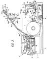
- Fig. 2 is a cross-sectional side view showing the state where the apparatus shown in Fig. 1A is opened.
- Fig. 3 is a perspective view showing the vicinity of a platen roller.
- Fig. 4 is a perspective view showing an exhaust sheet roller.
- Fig. 5 is a perspective view showing a recording frame.
- Fig. 6 and Fig. 7 are side views showing the vicinity of a recording head.
- Fig. 8 is a perspective view showing the recording head.
- Fig. 9 is a perspective view showing the vicinity of a cap.
- Figs. 10A - 10C are views showing the state immediately after the head and the cap are in contact with each other.
- Figs. 11A and 11B are views showing the state where the head and the cap are apart from each other.
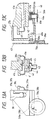
- Figs. 12A - 12C are views showing the state where the cap is being moved towards the head.
- Figs. 13A - 13C are views showing the state where a projection presses a nozzle to be tightly closed while a spring is resiliently deformed.
- Figs. 14A - 14C are views showing the state where the cap is being parted from the head.
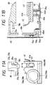
- Figs. 15A - 15C are views showing the standby state of the cap.
- Fig. 15D is a view showing a guide member used with the present invention.
- Fig. 15E is a view showing a further guide member used with the present invention.
- Fig. 16 is a typical view schematically showing a structural example of the ink supply passage of an ink jet recording apparatus using the present invention.
- Fig. 17 is a perspective view showing a structural example of ink supplying means of an ink jet recording apparatus.
- Fig. 18 is an exploded perspective view showing a structural example of an ink cartridge installed in an ink jet recording apparatus
- Figs. 19A and 19B are a partially cutaway sectional side view showing the structural example of the ink cartridge and a partially enlarged view thereof to show the state of mating with the ink supplying means.
- Fig. 20 is a partially cutaway sectional front view of the structural example of the ink cartridge.
- Fig. 21 is a schematic top view showing the structural example of the ink cartridge.
- Fig. 22 is a flowchart showing an example of sequential recovery applicable to an ink jet recording apparatus using the present invention.
- Figs. 23A - 23D are schematic side views sequentially showing the recovery operation.
- Fig. 23E is a typical view showing the contacting amount and contacting angle of the leading end of a blade being in contact with the face of a discharging port.
- Fig. 24 is a flowchart showing an example of the sequence from the standby state to the recording state.
- Fig. 25 is a block diagram showing a recording unit incorporating an embodiment of the present invention.
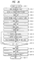
- Fig. 26 is a flowchart showing an operation at the time of recording.
- Fig. 27 is a flowchart showing a recovery operation according to an embodiment of the present invention.
- Hereinafter the present invention will specifically be described in accordance with embodiments.
- Fig. 1A is a central sectional view showing an embodiment of facsimile apparatus characteristically representing the use of the present invention. Fig. 1B is a top plan view thereof, and Fig. 2 is a cross-sectional view showing the apparatus in an open state. The facsimile apparatus of the present embodiment roughly comprises original conveying system A, optical system B, power source unit C, electric circuit board D, recording sheet conveying system E, decurling system F, ink supply system G, and recovery system H. Here, aforesaid original conveying system A and optical system B constitute an original reading unit for reading original images. Then, as the basic action of a facsimile apparatus, when an original 2 is set for transmitting or copying, original coveying system A conveys the aforesaid original 2 sequentially by a roller train (rollers R1, R2, R3, and R4) driven by driving means (not shown) in order to read the original image of original 2. Thus, the original line information is transferred by condenser lens Le to line
CCD 100 through the reflective optical path of optical system B (lamp L1, mirrors M1 and M2) from a given position for reading the original line (main scanning line) in the course of its conveyance, and is converted into electrical signals for the reading of the original information. At the time of receiving or copying, recording sheet conveying system E sequentially conveys recording sheet, which is wound in roll, by a roller train driven by driving means (not shown) to a passage shown in Fig. 1, and recording is performed in the course thereof by discharging ink from discharging ports ofrecording head 38 onto a given recording line of the recording sheet. Ink is discharged from the discharging ports ofrecording head 38 with the utilization of heat energy. This heat energy is generated by an electric heat converter provided inrecording head 38. In this respect, power source unit C received a normal AC to convert it into all the necessary voltage currents and supplies them respectively to each of the units of the apparatus. The electric circuits with electric circuit board D at its center controls the functional operation of each unit of this apparatus mainly with a cimcrocomputer system provided. It also performs the connection and disconnection with transmission line as well as the input and output of image information signals. Ink supply system G supplies ink to the recording head, and recovery system H performs the cleaning and capping of the face of discharging ports, which are needed for the maintenance of the head. - In this respect, as shown in Fig. 1B, rolled
recording sheet 1 is positioned almost in the center of the apparatus, and on the left-hand side thereof, original conveying system A, optical system B, and power source unit C are arranged in the vertical direction, and on the right-hand side thereof,recording head 38, record head recovery system H, and ink supply system G withink tank 86 are arranged sequentially in that order from the above. Since recordinghead 38, recording head recovery system H, and ink supply system G are thus arranged sequentially from the above, the ratio of pressure variation ofink tank 86 against the orifice face ofrecording head 38 is reduced (i.e., the pressure against each of the discharging ports is equalized) even if the apparatus is inclined, and an excellent recording can be performed. This is due to an arrangement such that despite the miniaturization of the apparatus, the space between the orifice face of recording head and theink tank 86 is made greater. - Hereinafter, each structure of recording head and operation will be described following its operational sequence.
Rolled recording sheet 1 is installed, and is pinched by drivingfeed roller 7 and free roller (platen roller) 8 which is in contact with said drivingroller 7 through decurling system F for straightening out the curl formed on thisrecording sheet 1.Feed roller 7 is driven by driving means (not shown) with, for example, a stepping motor as its power source. - Here, Fig. 3 is a perspective view showing parts arranged in the longitudinal direction in the vicinity of free roller 8 (platen roller). A first
platen side plate 13a and a secondplaten side plate 13b fixed to or integrally formed withrecording frame 19 supportfree roller 8 with a play in such a manner that the shaft of the free roller is penetrated through theopening 13c provided each of the side plates, having a larger diameter than that of the shaft. The E rings 29 and 30 are fixed respectively at both ends of the shaft offree roller 8 as locks and further, on both shaft parts offree roller 8,bearings free roller 8 to enable it to be freely rotated. In the meantime, the aforesaid firstplaten side plate 13a and secondplaten side plate 13b are slidably arranged each with the respectiveplaten pressure shaft springs platen pressure shafts bearings free roller 8 respectively to exert pressure against each of them. - Now, reverting to Fig. 1,
recording head 38 is at the recording position. At this juncture,free roller 8 is positioned by being in contact in two directions withfeed roller 7 by the pressure exerted byfree roller 8 as well as withrecording head 38 by contacting theaforesaid bearings platen pressure shafts free roller 8 are exerted, is set towards the direction thatfree roller 8 is in contact withfree roller 7 and thatbearings recording head 38. At the same time,recording guide 14 made of thin plastic plate guides theaforesaid recording head 38, so that the recording head is rotated to the recording position withhead shaft 36 as its rotational center. - Thus, the sheet path is matched with the recording line position, and
recording head 38 discharges ink from its discharging ports onto the aforesaid recording line position for recording at the time of recording. - Next,
recording sheet 1 is pinched by firstexhaust sheet roller 21 and theroller train 17a - 17g androller train 18a - 18g which are in contact with the aforesaid firstexhaust sheet roller 21 to be conveyed while being guided byfirst curvature guide 15 and first exhaust sheet guide 20. - In this respect, the aforesaid first
exhaust sheet roller 21 is driven by the driving system of the same power source asfeed roller 7, and is so arranged that the peripheral speed of the aforesaid firstexhaust sheet roller 21 is slightly faster than that of theaforesaid feed roller 7. - Here, Fig. 4 is a perspective view showing the parts arranged in the longitudinal direction in the vicinity of first
exhaust sheet roller 21.Rollers 17a - 17g androller 18a - 18g are arranged alternatively with first curvature guides 15a - 15f. Each of them is rotatably supported byshaft 31 andshaft 32 and both ends of the shafts are locked by E rings, etc. Also, at both ends,shaft 32 is regulated by receiving side 9a of the first exhaust sheet rollers, which is fixed to or integrally formed withrecording frame 19 and receivingside 19b of the second exhaust sheet rollers, and also in the horizontal direction, the shaft is regulated at both ends thereof by the vertically elongated through holes having the diameter fitted to that ofshaft 32, through which the shaft is penetrated. The both ends of the shaft are also locked by E rings (not shown), etc. In this respect, compression is generated bysprings 16a - 16f represented only by areference numeral 16a in Fig. 4 forrecording chassis 19 and first curvature guides 15a - 15f (refer to Fig. 1) to causerollers 17a - 17g androller 18a - 18g to be in contact withexhaust sheet roller 21 by pressure. As a result, when recordingsheet 1 is pinched thereby, the power to convey the recording sheet is generated. Then, recordingsheet 1 is guided to upperexhaust sheet guide 23 and trailingexhaust sheet guide 24 through the space between bothedges exhaust sheet roller 25 and the rollers 27a - 27g androllers 28a - 28g which are in contact therewith. In this respect, secondexhaust sheet roller 25 is also driven by the driving system in such a manner that the peripheral speed thereof is set at a speed slightly faster than that of the aforesaidfirst roller 21. Here, too, as in the vicinity of the aforesaid firstexhaust sheet roller 21, rollers 27a - 27g androllers 28a - 28g are arranged alternately with second curvature guides 26a - 26f and are rotatably supported respectively byshaft 33 and shaft 34. Then, both ends of shaft 34 are locked with E rings, etc.Shaft 33 is regulated at both ends thereof by exhaust sheet roller receiving sides 19c and 19d fixed to or integrally formed withrecording frame 19, having vertically elongated holes fitted respectively to the diameter ofshaft 33, through which both ends of the shaft are penetrated horizontally. The ends thereof are also locked by E rings, etc. Withsprings 35a - 35f, compression is generated betweenrecording frame 19 and second curvature guides 26a - 26f (refer to Fig. 1) to cause rollers 27a - 27g androllers 28a - 28g to be in contact with secondexhaust sheet roller 25 by pressure, so that when recordingsheet 1 is pinched thereby, the conveying power is generated. In this way, the recording sheet is exhausted after recording has been completed, and is further conveyed byexhaust sheet roller 39 in the form of being cut into the unit of one page while the leading end thereof is being held smoothly bystacker 40. As a result, an operator can take out the recording sheet thus stacked onstacker 40. - As the above describes, the recording sheet conveying system is structured to carry out its operation. Here, Fig. 1 shows the state of the system at the time of recording, and at the time of replacing the recording sheets or troubleshooting in conveying recording sheet,
recording frame 19 can be opened or closed withhinge 19e ofrecording frame 19 as its pivoting point. In other words, as shown in Fig. 2, the recording frame can be opened just along the recording sheet conveying path as its boundary, and the arrangement is designed to place each of the components belonging torecording frame 19 above this boundary and each of those belonging tomain body frame 63 below the boundary. Thisrecording frame 19 and the assembly of its components thereon are shown in Fig. 5. - As set forth above,
recording head 38, recording head recovery system H, and ink supply system G are sequentially arranged from the above in that order. Thus,recording sheet 1 is guided in the horizontal direction above recordinghead 38 after the recording has been completed by recordinghead 38, and is further conveyed downwards thereafter toexhaust sheet stacker 40 for stacking. Here, the path through which the aforesaid recording sheet is being guided in the aforesaid horizontal direction forms the aforesaid boundary along which the main body is opened. Therefore, it is easy to remove a clogged sheet if any clogging should occur, and further, it is possible to perform capping without damaging the head face when a sheet clogging takes place. In addition, should an ink leakage occur while capping, the recording sheet is not stained. - Next, the positioning of free roller 8 (platen roller) will be described.
- First, Fig. 6 illustrates the state of parts in the vicinity of
free roller 8 when the main body of the apparatus is in standby. Recordingguide 14 is not allowed to be in contact withfree roller 8 unless there is external force to be exerted thereon. Accordingly, the contacting angle ofrecording sheet 1 to the periphery offree roller 8 is less in the standby state than in the printing state. At this juncture, the position offree roller 8 is established by the fact that the periphery offree roller 8 is pressed by platenpressing shafts feed roller 7, and that the shaft offree roller 8 is in contact with throughhole 13c, which is larger than the periphery of the aforesaid shaft by 0.1 mm - several mm, provided on each ofplaten side plates aforesaid feed roller 7 andfree roller 8 are made of plastic material such as rubber, etc. rolled around rigid shaft made of iron, etc. - Next, Fig. 7 illustrates
recording head 38 being rotated clockwise with head shaft as its rotating center in order to shift itself from the standby state to recording state. Whenhead 38 is first rotated as described earlier by the driving power generated by motor KM, a plurality of projections provided on the recording face ofhead 38 are in contact with the top of recordingguide 14 to causerecording guide 14 to begin resiliently deforming it. Here,projection 38c provided on the recording face ofhead 38 is made to be increasingly higher towards the corner. Thus, recordingguide 14 is deformed apart from recordinghead 38 by the height (δ in Fig. 7) of the aforesaid projection. - The reason why the
aforesaid projection 38c is arranged to be increasingly higher towards the coner is to make it easier to remove ink when the recording face of the head is wiped as described later. - Recording
head 38 is further rotated clockwise, and when recordinghead 38 is moved to be in the recording state as shown in Fig. 1, both ends of the recording face ofrecording head 38 are in contact withbearings recording head 38 and platen roller (free roller) 8 is established. Here, the periphery ofbearings free roller 8, and the volume thereof is set to be less than the height δ of the aforesaid projection ofrecording head 38 by a 1/several mm thereof. Thus, guide 14 is reliably in contact with the periphery ofplaten roller 8 to convey the recording sheet. Here, at the time of recording, theaforesaid feed roller 7 is rotated clockwise, andplaten roller 8 is rotated counterclockwise by the external force generated by the feed roller, at the same time, being moved in the direction towards the recordinghead 38. Hence, with the structure described earlier, theaforesaid platen roller 8 is brought to contact withguide 14 through recording sheet. Therefore, theaforesaid springs platen roller 8 can also be in contact with the guide only by its own weight. - Next, using the perspective view shown in Fig. 8, the structures of peripheral parts of
recording head 38 will be described. Recordinghead 38 mainly comprises headmain body 38f including a heat generating section, electrical part section, and glass chamber section for containing liquid ink,front filter 38d andrear filter 38e arranged respectively at the outside of the head main body, and headfront plate 38c. Also, fronthead ink connection 38d1 and rearhead ink connection 38e1 are respectively provided forfront filter 38d andrear filter 38e. These are tightly closed and connected respectively byfront ink supply 71 and ink supply tube threading with sealing members (not shown) provided therebetween. Areference numeral 38a designates an imaginary two-dot chain line in Fig. 8 to represent the straight line formed by connecting the center lines of the nozzles aligned. A plurality of nozzles are aligned in order to form image on a recording material across the entire width thereof in the direction of main scanning. Hereinafter, these are referred to asnozzle 38a. In practice, however, holes of several ten microns in diameter are provided, and the aforesaid holes are connected toink supply tubes ink supply tubes reference numeral 38b designates the face wherenozzle 38 is open, which is called orifice face. In this respect, front head plate 38g is formed by metal or molding material, and the space betweenorifice face 38b and front head plate 38g is filled with silicon rubber, etc. to close them completely.Filters Reference numerals recording head 38 by means of screw, etc. -
Front head arm 37a andrear head arm 37b are fixedly mounted onhead shaft 36 by means of screw, etc., and with the structure as described earlier,head shaft 36 andrecording head 38 are fixedly arranged.Head shaft 36 is rotatably supported by main body frame 56 through bearings (not shown).Head shaft 36 is connected to driving system comprising gears, belts KB, etc., and is further connected to stepping motor KM. - Next, using the perspective view shown in Fig. 9, the structure of peripheral parts of
cap 41 will be described. Although the shape ofcap 41 will be described later in detail later,cap 41 is formed by plastic material such as silicon rubber, etc. which has a high resistivity against mechanical creep as well as a high ratio of permeability for water vapor, etc. Areference numeral 42 designates a cap keel made of rigid material such as aluminum, stainless steel, etc., and as shown in a cross-sectional view in Fig. 10,short shafts cap keel 42 by means of screws.Short shafts 46a - 46e should desirably be made of a corrosion-inhibiting and rigid material such as stainless steel, etc. In the present embodiment, althoughshort shafts 46a - 46e are fixed by screws, these can also be coupled by means of press fitting, bonding, or the like. Also,cap keel 42 andshafts 46a - 46e can be formed integrally by means of molding, etc. - Here, the formation of
cap 41 is first made bycoupling cap keel 42 andshort shafts 46a - 46e as described above. Then, the coupledcap keel 42 andshort shafts 46a - 46e are buried into an open forming die, and by putting silicon rubber, which is also the original material ofcap 41, into the die or sandwiching silicon rubber betweencap 41 andcap keel 42, these are integrally formed by burning into a one body. Here, the shape of the aforesaid forming die should match the external contour ofcap 41 as a matter of course. Now, areference numeral 60 designates a recovery frame made of a corrosion-inhibiting rigid material such as stainless steel, and the four sides of recovery frame are bent to rise (60a - 60d) in order to enhance the rigidity. Torecovery frame 60,short shaft bearings short shafts 46a - 46e. In this respect, the method forcoupling bearings 61a - 61e withframe 60 may also be either welding or bonding. Also, as described later,short shaft 46a is fitted into an elongated hole whileshort shafts 46b - 46d are fitted into the so-called loose holes, andshort shaft 46e is fitted to perform positioning. In other words, each of theshort shafts 46a - 46e has a same outer diameter, and theinner diameter 61e1 of short shaft bearing 61e and the outer diameter ofshort shaft 46e are made to just fit each other.Short shaft bearings 61a - 61e are made of polyacetal resin having excellent slidability against stainless steelshort shaft 46e. - As shown in Fig. 9, an
elongated hole 61a1 is formed for short shaft bearing 61a against short shaft bearing 61e in the longitudinal direction ofcap 41. Then, the dimension ofelongated hole 61a1 in the transverse direction is formed to fitshort shaft 46a. The diameters ofholes short shaft bearings short shafts 46b - 46d within a rage of 0.1 mm - 1 mm. Then, at the outside ofshort shafts 46a - 46e, compression springs 47a - 47e are respectively held by screws from the reverse side ofrecording frame 60 withshort shaft stoppers 56a - 56e sandwiched as shown in Fig. 9. - Compression springs 47a - 47e are pressed between the cap keel and
short shaft bearings 61a - 61e because the springs are held by screws. The movement ofcap 41 at this juncture will be described later. - Next,
first wiper 50 andsecond wiper 52 are made of plastic material such as rubber, etc. having a good abrasion resistance, and the straight portions of leadingends second wipers first wiper 50 andsecond wiper 52 are respectively fixed tofirst wiper stay 49 andsecond wiper stay 51 by means of screws, etc. (not shown). First and second wiper stays 49 and 51 are both made of corrosion-inhibiting rigid metal such as stainless steel, etc. - Further, as shown in Fig. 9,
first wiper stay 49 andsecond wiper stay 51 are held onrecovery frame 60 by screws, and theprojection 41a ofcap 41, which will be described later, and the wiper leading ends 50a and 52a are arranged to accurately parallel themselves at this juncture. Also theaforesaid projection 41a, wiper leading ends 50a and 52a, and the mounting face ofrecovery frame 60 for wiper stays 49 and 51, and the imaginary two-dot chain line α in Fig. 9 connecting the center lines ofboss sections front cam gear 59a andrear cam gear 59b are arranged to be in parallel accurately as described later. Also, as shown in Fig. 9, the structure is formed to enable the height of theleading end 52a of second wiper againstrecovery frame 60 to be higher than that of theleading end 50a of first wiper againstrecovery frame 60. In order to provide this structure, it is possible to change either the heights of the aforesaid plastic portions made of rubber, etc. of first andsecond wipers reference numeral 54 designates a recovery frame bearing, andrecovery frame shaft 55 shown in Fig. 1C (control cross-sectional view) is allowed to fit theelongated hole 54a of recovery frame bearing 54 in the transverse direction. Here, in this respect,recovery shaft 55 is fixed tomain body frame 63, butrecovery frame shaft 55 may also be supported rotatably bymain body frame 63. Recovery frame shaft bearing 54 is made of polyacetal resin having a good slidableness and is fixedly screwed torecovery frame 60. Recovery frame bearing 54 is fixed againstrecovery frame 60 in the direction indicated by arrow β in Fig. 9 at a position which enables the center of the depth ofelongated hole 54a to be in the central part ofrecovery frame 60. Also, here, the center ofhole 61c1 of short shaft bearing 61c is positioned in the central part ofrecovery frame 60 in the direction indicated by arrow β as shown in Fig. 9. Further, the center ofhole 61b1 of short shaft bearing 61b and that ofhole 61d1 of short shaft bearing 61d are symmetrically positioned in the direction indicated by arrow β with shortshaft bearing hole 61c1 as the center. Also, the center ofelongated hole 61a1 of short shaft bearing 61a in the direction indicated by arrow β and the center ofhole 61e1 of short shaft bearing 61e are likewise positioned symmetrically in the direction indicated by arrow β with thehole 61c1 as the center. Now, it is desirable to equalize four distances between the centers of holes, i.e. the distance between the centers ofholes reference numeral 62 designates a recovery frame shaft which is arranged across both of the side plates ofmain body frame 63. Thisrecovery frame shaft 62 is rotatably supported around a bearing (not shown) provided inmain body frame 63. Further, to thisrecovery frame shaft 62,idler gears main body frame 63 and outside thefront cap guide 48a andrear cap guide 48b which will be described later. In view of assemblingrecovery frame 62 inmain body frame 63, parallel pins or spring pins (both not shown) and E ring stopper are used as means to fix idler gears 57a and 57b torecovery frame shaft 62. Further, torecovery frame shaft 62,outer idler gear 58 is fixed with D cut portion formed at an end ofrecovery frame shaft 62 as its rotation stopper, withmain body frame 63 being sandwiched as shown in Fig. 9. Then, toidler gear cam gear shafts main body frame 63 respectively at positions outside the cap guides 48a and 48b and inside themain body frame 63. Here, the modules and number of teeth ofgears gear 58 andgears gear 58 is connected to stepping motor CM. - As above describes, the number of teeth thus arranged enables the gears engaged with cam gears 59a and 59b to rotate one round exactly the same as the cam gears completing one round, so that the rotational angles and positions of these gears are detected by a microswitch slit type sensor (not shown), etc. to detect the position of the
boss section 59a1 ofcam gear 59a and theboss section 59b1 ofcam gear 59b. Therefore, if only a gear, a timing pulley, or the like, which should complete one round in synchronism with the one rotation of cam gears 59a and 59b, is arranged in the driving system for detecting the position of such gear, timing pulley, or the like, it is not necessary to make the number of teeth identical to each of thegears recovery frame 60, cap guides 48a and 48b are fixedly mounted in addition to these gears. Cap guides 48a and 48b are made of polyacetal resin having a good slidableness. Then,grooves boss sections boss section 59a1 andboss section 59b1 are arranged at positions just opposite to each other. - Since the structure is of such as described above,
recovery frame 60 performs rocking motion in the direction indicated by arrow X in Fig. 10 (central cross-sectional view) withrecovery frame shaft 55 as the center when outeridler gear 58 is rotated. - Now, since the vicinity of
recovery frame 60 is constructed with the parts described as above,recovery frame 60 is positioned by the plane formed by two-dot chain line α andrecovery frame shaft 55 as shown in Fig. 9. Here, two-dot chain line α andhead shaft 36 are arranged to be accurately in parallel. Althoughrecovery frame 60 is positioned by the plane formed by the aforesaid two-dot chain line α andrecovery frame shaft 55, it is not fixed by the aforesaid structural members.Recovery frame 60 is structured to be flexible in the direction indicated by arrow θ and by curbed arrow γ in Fig. 9. - Next, using Fig. 11, the arranging position of first
recovery cap guide 48a andsecond cap guide 48b is the direction indicated by arrow θ in Fig. 9 towardsrecovery frame 60 will be described in detail. On both first and second cap guides 48a and 48b, Uletter type holes recovery frame 60 to allow the center of the shorter width ofprojection 41a (indicated by arrow in Fig. 11) ofcap 41 to be placed in the center of the aforesaid space of U letter holes 48a1 and 48b1. - Next, on
first head arm 37a andsecond head arm 37b,circular projections front head arm 37a andrear head arm 37b. Then, the arranging positions of the aforesaidcircular projection nozzle section 38a to be placed in the central position of the circular projection. Also, the diameter of the aforesaidcircular projections - Now, since the structure is arranged as described above, when
recovery frame 60 is raised by the rotation of cam gears 59a and 59b at the time of capping,circular projections head arms nozzle section 38a andprojection 41a ofcap 41 are just oppositely placed. - Here, in the present embodiment,
recovery frame 60 can be displaced in the direction indicated by arrows θ and γ (in Fig. 9) by the construction as described earier. Therefore, according to the present embodiment, even when there is a slight difference in the positions of the aforesaid U letter holes 48a1 and 48b1 andprojection slant 48c andholes only projections slant 48c of U letter holes 48a1 and 48b1. - Further, the positioning of
cap 41 andfront head plate 38c, which will be described later, is performed naturally in this course of event. Also, even ifrecovery frame 60 approachesnozzle orifice face 38b with some inclination,projection 41a andnozzle section 38a can approach each other with the face to face positional relationship. - Next, using Figs. 10 through 15, the shapes and movement of
cap 41,cap keel 42,valve 43,valve cover 44, and waste ink tube will be described. - Fig. 10 illustrates the state immediately after
head 38 andcap 41 are in contact with each other. Fig. 11 illustrates the state whenhead 38 andcap 41 are parted. Fig. 12 illustrates the state whencap 41 is moved forwards toward thehead 38. Fig. 13 illustrates the state whereprojection 41a closesnozzle 38a by pressure, and spring 47 is resiliently deformed. Fig. 14 illustrates the state wherecap 41 is parted fromhead 38, and Fig. 15 illustrates the standby state. In each of the figures, A is a side view observed from the location of side plate; B is a cross-sectional view in the transverse direction; and C is a cross-sectional view in the longitudinal direction. In Fig. 11, however, A is also a side view but B is a cross-sectional view in the longitudinal direction. - At first, Figs. 10A through 10C illustrate the state representing the
moment cap 41 has come into contact withfront head plate 38c.Cap 41 has not been deformed yet. In conjunction with Fig. 10B, the cross-sectional shape ofcap 41 is described in detail. The side portions ofcap 41 are formed with inclination so as to widen the distance between them as the cap is raised upwards as shown in Fig. 10B. The inclined side portions are connected to the curbed portions indicated by mark a in Fig. 10B, and the thickness of the portions a are made thinner than the other portions as illustrated in Fig. 10B. Although, in the present embodiment, the portions a are formed with a smooth curvature, these portions may also be formed in an abrupt edge. In the case of an abrupt edge in which these should be formed, the thickness of such edge portions could be made thinner. Likewise, in Fig. 10C, the cross-sectional shape ofcap 41 in the transverse direction is formed to open itself towards the outside as it is raised upwards as in Fig. 10C. - The cross-sectional shape of
cap 41 in the transverse direction is formed in such a manner that the thickness ofcap 41 contacting withfront head plate 38c is made thicker than that of the cross-sectional shape ofcap 41 in the longitudinal direction shown in Fig. 10B also contacting the aforesaidfront head plate 38c. This is due to the fact that although the positioning ofcap 41 againsthead 38 in the transverse direction is accurately performed, the positioning in the longitudinal direction is not performed accurately. Therefore, such construction as is the present embodiment may not be needed if only the positioning ofcap 41 againsthead 38 is accurately performed in the longitudinal direction. Now, reverting to Fig. 10C, the side portions ofcap 41 are connected to curbed portions b which change its shape smoothly as in Fig. 10B, and the thickness of portions b is made thinner. In the present embodiment, the shape ofcap 41 in Figs. 10B and 10C is such that the thickness thereof becomes increasingly thinner smoothly towards the cap bottom as illustrated in these two figures. Now, reverting to Fig. 10B, in the closed space incap 41,projection 41a integrally formed withcap 41 is provided. The arranging position ofprojection 41a is defined so as to allow the top of R shapedportion 41c ofprojection 41a to be located at a position againstnozzle section 38a. The length ofprojection 41a in the longitudinal direction at both ends is made longer than the entire length in whichnozzle section 38a is arranged. Next, throughhole 41b is provided oncap 41. The throughhole 41b incap 41 is matched with throughhole 41b provided oncap keel 42. Then, in the aforesaid throughhole 41b,valve 43 is fitted. Theaforesaid valve 43 being formed with plastic material, it can produce a state which is closed from the atmosphere without any pressure exerted onvalve 43. Here, the reason whyvalve 43 can properly function as a valve is that thecap keel 42 is formed with rigid material as described earlier, the contact face betweenvalve 43 andcap keel 42 being formed with excellent precision. - Next, around
valve 43,valve cover 44 is mounted to enclosevalve 43, and capkeel 42 and valve cover 44 are closedly fixed. Further,valve cover 44 is closedly coupled withwaste ink tube 45.Cap 41 begins to approachrecording head 38 from the state shown in Fig. 10 by the rotation of cam gears 59a and 59b in the direction indicated by arrow d in Fig. 10A. Along the movement of theaforesaid cam gear cap 41 begin to move in the directions indicated by arrow c in Fig. 10B and Fig. 10C while maintaining contact withfront head plate 38c. This movement occurs because the sides ofcap 41 are formed to open as the cap is raised upwards. Now,cap 41 is moved in the direction indicated by arrows c due to the shape ofcap 41. In addition to this, the movement is due to the increasing pressure in the closed space incap 41 resulting from the reduction of volume of the closed space incap 41. As the pressure in the closed space incap 41 increases,valve 43 begins to open, and air in the closed space begins to flow fromvalve 43 and waste ink (not shown) begins to flow towardswaste ink tube 45. Further, Fig. 12 illustrates the state where cam gears 59a and 59b have rotated in the direction indicated by arrow d. - In Fig. 12B, the side of
cap 41 is in contact with the rising portion of the edge offront head plate 38c and the movement in the direction indicated by arrow c in Fig. 10 is stopped. The side ofcap 41 in the transverse direction shown in Fig. 12C is formed thinner than the thickness of the side in the longitudinal direction as described earlier. Therefore, its movement in the direction indicated by arrow c is stopped by the rigidity of the side itself. In the present embodiment, the thickness of the side ofcap 41 shown in Fig. 12C is changed as described earlier, but if the thickness of the side ofcap 41 in the transverse direction is made thin as in the case of the thickness of the side in the longitudinal direction as described above, the same faction as the present embodiment can be materialized by allowing the side to be in contact with the rising portion of the edge offront plate 38c. - Now, in Fig. 12B, the portions a of the sides of
cap 41 are deformed as shown in Fig. 12B due to bending stress generated after the sides of the cap are in contact with the edges offront head plate 38c. The thick portions including the contacting faces of the sides ofcap 41 receive buckling load, and the aforesaid portions a, being deformed to bend, are not buckled. This results in the similar deformation taking place in the sides ofcap 41 including the portion b in Fig. 12C which is also being deformed. Here, in Fig. 12C,compression spring 47a has not been pressed as yet. - In Fig. 12B, the pressure in the aforesaid closed space generated by
cap 41 becomes higher than the pressure in the state represented in Fig. 10, andvalve 43 is released to flow air in the closed space incap 41 and the aforesaid waste ink to wasteink tube 45. - In this respect, when cam gears 59a and 59b are further rotated in the direction indicated by arrow d, cap 41 further approaches
head 38 and theprojection 41a ofcap 41contacts nozzle 38a. Here, there is almost no deformation ofcap 41 with the exception ofprojection 41a. Also, when cam gears 59a and 59b are still further rotated in the direction indicated by arrow d,compression spring 47a begins to deform, and the reaction generated by theaforesaid compression spring 47a causesprojection 41a ofcap 41 to pressnozzle section 38a. In this respect, onlycompression spring 47a is illustrated in Fig. 10 through Fig. 15, but the other compression springs 47b, 47c, 47d, and 47e function in the same way ascompression spring 47a. Here, the time needed for theaforesaid projection 41a to pressnozzle 38a is approximately several seconds which are required for liquid ink to circulate inhead 38. At this juncture, a pump is actuated to circulate liquid ink. - In the above-mentioned embodiment the
cap 41 and theprojection 41 a are integrally formed of an elastic material such as rubber. However, the whole body of thecap 41 may have no elasticity when at least the headdischarge port surface 38c and the contact section are elastic and in this case a remaining upper part thereof may be of steel. - Now, Fig. 13 illustrates the state where
compression spring 47a is deformed as the above describes, andboss sections cap 41, andvalve 43 only shows the state to close air. Therefore, the pressure in the closed space is equal to the atmospheric pressure. Hereinafter, the state of each part, when cam gears 59a and 59b are rotated from the state shown in Fig. 13 in the direction indicated by arrow e, will be described. Now, the rotational direction of cam gears 59a and 59b means the required movement ofboss sections cap 41 is again increased and the pressure in the closed space becomes negative against the atmosphere, andvalve 43 is closed as shown in Fig. 14. Therefore, in order to supplement the reduced volume in the closed space incap 41, ink is discharged fromnozzle section 38a ofrecording head 38. Ink remaining innozzle section 38a is refleshed. - Finally, Fig. 15 illustrates the pheripheral
parts including cap 41 being in the standby state where the apparatus has not started performing operation such as recording, recovering, etc. In Fig. 15, the cam gears are at rest. In Fig. 15B, the pressure in the closed space incap 41 is identical to the atmospheric pressure. At this juncture, there is no force exerted onvalve 43 either to open or close tovalve 43. However, due to the shape ofvalve 43, water vapor in the closed space incap 41 is not released into the atmosphere. - Fig. 15D is a view showing another embodiment of a guide member. On
first cap guide 48a andsecond cap guide 48b, V letter holes 48a2 and 48b2 are respectively formed, and the spaces in V letter holes are formed with excellent precision. - Next, on
first head arm 37a andsecond head arm 37b,square projections - Then,
first head arm 37a2 andsecond head arm 37b2 are arranged to allow the leading ends of square projections thereof 37a3 and 37b3 to mate respectively with V letter holes 48a2 and 48b2 when the projection ofcap 41 is in contact withnozzle section 38a ofhead 38. - With a structure such as this, even if there is a slight difference in the positions of the aforesaid V letter holes 48a2 and 48b2 and the aforesaid
square projections recovery frame 60 enables theholes 48a2 andprojection 37a3 and thehole 48b2 andprojection 37b3 to be mated reliably because the frame can displace itself in the directions indicated by θ and γ in Fig. 9. - Fig. 15E is a view showing still another embodiment of a guide member. On
first head arm 37a4 andsecond head arm 37b4, U letter holes 37a5 and 37b5 are respectively formed, and the spaces of U letter holes are formed with excellent precision. - Next, on
first cap guide 48a andsecond cap guide 48b,circular projections - Then,
first head arm 37a4 andsecond head arm 37b4 are arranged to allow the leading ends of U letter holes 37a5 and 37b5 to fitcircular projections cap 41 is in contact withnozzle section 38a ofhead 38. - With a structure such as this, even if there is a slight difference in the positions of the aforesaid
circular projections recovery frame 60 enables theprojection 48a3 andhole 37a5 and theprojection 48b3 andhole 37b5 to be mated reliably because the frame can displace itself in the directions indicated by arrows θ and γ in Fig. 9. - Next, the ink supply and recovery systems will be described. This unit comprises an ink tank, ink tubes, an ink pump, etc. to keep ink and supply it regularly to a recording head and to remove bubbles generated in the tubes, etc., as well as anything that may clog nozzles.
- Fig. 16 is a view illustrating the concept of such a system. In Fig. 16, an ink cartridge comprises
recording head 38,ink pump 76,ink tank 86,waste ink absorber 96, andair duct 87 which is called breezer. - The initial ink supply to
recording head 38 is carried out in a manner given below. In other words,ink pump 76 is actuated in a state wherecap 41 is closely contacted with the recording head (a state shown in Fig. 13 whereprojection 41a incap 41 is in contact withnozzle section 38a of recording head 38) to circulate ink fromink cartridge 86 in the direction indicated by arrow E, so that the inside of the tubes including the inside of the recording head is filled with ink. - When the initial ink supply is completed,
recording head 38 is ready to discharge ink. The ink pump used here is a pump which does not close the flow passage when the pump is at rest. Therefore, the ink supply at the time of discharging is carried out from both front and rearhead ink couplers - When ink is reduced due to discharging, air should be drawn into the tank in an amount equal to the reduced amount of ink.
Breezer 87 functions as an air duct for this purpose. In thisbreezer 87, check valves capable of being opened by an extremely small difference in pressures are respectively arranged in both directions. Therefore, the valves function if a slight pressure, either negative or positive, is generated in the tank, and operate as air holes substantially. However, the valves are also arranged to control dust intrusion and evaporation. - A
reference numeral 92 designates a no-ink detector for detecting no-ink condition intank 94. The detection is carried out in a manner given below. In other words, sincefloat chamber 90 is open to the atmosphere throughbreezer 87 which is commonly provided forink tank 94, the liquid level therein and float 89 which floats thereon indicate the same water level 91a asliquid ink level 91 inink tank 94. Therefore, at an appropriate location in the lower part offloat chamber 90,sensor 88 is arranged for detecting a light interruption. Thus, whenliquid level 91 is lowered, i.e., float 89 is lowered following the lowering of water level 91a in the area for detection, the emitting light from thesensor 88 is interrupted, thereby detecting the no-ink condition. - Next, the recovery operation is described. The recovery operation is an action to remove bubbles and cloggings which bender the normal discharging, and is performed in accordance with the recovery sequence, which will be described later, controlled by the recovery system. The recovery operation, however, is exactly the same as the initial ink supply operation. In other words,
ink pump 76 is actuated whilecap 41 is in contact with recording head 38 (the current state is illustrated in Fig. 13) to circulate ink in the direction indicated by arrow A, so that bubbles are collected into the ink tank to release them to the outside through the breezer. Then, the contacting condition betweenprojection 41a incap 41 andnozzle 38a is released to drive the pump for the removal of any clogging in the nozzle. When pressurized ink is flown intofloat chamber 90,float 89 is raised to closely contact with upper face offloat chamber 90 to cover the passage tobreezer 87. Therefore, no ink is flown intobreezer 87. - Fig. 17 is a perspective view showing the construction of supply and recovery systems, in which the structure described above is actually employed. In Fig. 17, a
reference numeral 73 designates the base of this unit which also functions as a base for installingink cartridge 86, which will be described later. Also, areference numeral 74 designates a member called joint plate which is formed by fixing each of various passage couplers. To thisjoint plate 74, there are coupledcartridge guide 78 forpositioning ink cartridge 86,cartridge joints ink absorber 96 built inink cartridge 86 through waste ink tank, air joint 80 for connecting the breezer for releasing air withair tube 83, first and second supply tube joints 84 and 85 for connecting first and secondink supply tubes ink pump 76 which is driven bypump motor 77. Thus, ink joint 79 connected toink tank 94 accommodated inink cartridge 79a provides three functional sections intensively, firstink supply section 79a, secondink supply section 79b, and airpassage connecting section 79c, and with its structure, enables firstink supply inlet 95a, second ink supply inlet 75b andair inlet 95c to be coupled altogether, which are operationally related to the function ofink tank 94. - For this purpose, the air passage section leading to the ink tank is formed by joints, thereby making it possible to construct the ink tank with hard resin material to reserve a large quantity of ink without employing ink bags.
- Furthermore, by connecting first
ink supply inlet 95a and secondink supply inlet 95b, and firstink supply section 79c and secondink supply section 79b, an ink circulation passage is formed to perform ink supply from both of the ink supply regions at the time of recording and to circulate ink from the ink tank through the passage with the pump inbetween, and to circulate ink from the recording head to the ink tank again at the time of initial ink filling and recovery operation. - In other words, since the passage is formed by directly joining the tank and the supply passage, and further the air passage as described earlier, it becomes possible to eliminate, in spite of the ink tank being made of hard plastic resin, such function as a sub-tank which has conventionally been indespensable for a stable ink supply. In the present type, these members are separately fixed to
joint board 74, but the structure may also be such that these members are integrally formed with the joint board. - Further, to
joint board 74,flow passage board 75 is coupled withflow passage groove 75a which functions as ink flow passage. In this portion, most of the ink flow passage pipings and connections are installed. - In other words, by fixedly arranging
joint section 79 which is annexed tojoint board 74 connected toink tank 94, it becomes possible to provide a structure thereby eliminating the operation related toink passage 75a in that particular portion. - As a result, a part of ink passage from
ink tank 94 to the recording head can be formed only by coupling to the reverse side ofjoint board 79 theflow passage plate 75 which constitutes a flow passage. - On the other hand, as described later,
ink tank 94 built inink cartridge 86 is flexibly accommodated inhousings cartridge 86. - By accommodating the ink tank flexibly, it is possible to reliably adjust with ease the coupling condition of the cartridge which should be installed against
joint section 79 which is flexibly arranged, and in this way, the installation of cartridge is carried out with assurance. - It is also possible to construct the ink passage from the ink tank without complicated piping arrangements simply by coupling
joint board 74 and flowpassage plate 75 to form the required flow passage. - As shown in Fig. 18, there are accommodated in
ink cartridge 86, thecommon housings ink tank 94 made of resin having a good property against fluid andwaste ink absorber 96 made of a water absorptive material having an excellent ink absorptive property such as felt or porous material. The ink supply and air releasing are performed by connecting these members withcartridge 79 on the side ofjoint plate 74 throughjoint section 95. Thus, theentire ink cartridge 86 is structured to be detachably installed as a whole onbase 73 provided on the side of the apparatus. - Figs. 19A and 19B illustrate the structure of this part in further detail. Fig. 19A is a partially cutaway cross-sectional side view showing the principal parts of ink cartridge
main body 86. Fig. 19B is a partially cutaway cross-sectional view showingjoint section 95 connected to the cartridge joint of the ink supply system. In order to prevent any ink leakage whenink cartridge 86 is removed,metal ball 99 is provided injoint section 95 to press it againstjoint opening 95a by the compression of spring 98. When the ink cartridge is detached from the unit,metal ball 99 is closely in contact with sealingrubber 101 to close theopening 95a of the joint section. - Also, as shown in Figs. 19A and 19B and Fig. 20 showing the front cross-section of ink tank, ink tank has sloped surfaces or
slants 94a, 94b at its bottom. In other words, there are provided slant 94a for gathering ink flow intojoint section 95 from behind, andslant 94b for gathering ink flow intojoint section 95 from the side ofink tank 94. Ink is supplied to the ink supply system through guidingtube 100 which is bent to be opened at the lowest bottom of the ink tank. Abottom support 93b supports the rear portion of the sloped surface 94a of theink tank 94. Thus, it is possible to collect all ink in the vicinity of guidingtube 100 by formingslants 94a and 94b at the bottom of ink tank, and to use ink without any waste. Also, it is possible to draw ink without a waste even if the apparatus is installed with a slight inclination. With a structure such as this, the area is provided in the housing to accommodate the aforesaidwaste ink absorber 96 substantially in U shape. - Furthermore, in the present example, it is necessary to couple three flow passages, i.e., two ink supply passages and one air releasing passage, at
joint section 95, but in order to obtain reliable couplings,ink tank 94 is held inhousings space 97 to allow the ink tank to move freely in an appropriate amount. - Especially, it is necessary to provide flexibility not only vertically and horizontally but rotatably when a plurality of joints should be connected. In the present embodiment, a slight rotatability is maintained to obtain a rotatable flexibility about the central axis of
joint section 95 by supportingink tank 94 with spaces 97 (in this embodiment, for example about 1.0 mm) andspaces 97a (for example, about 1.0 - 2.0 mm) provided for both ends ofink tank 94 and bywaste ink absorber 96 which is soft like felt. Aprojection 93d supports a front bottom of theink tank 94. Hence it is possible to make connections reliably without any deviations in positioning. In this embodiment thejoints ink tank 94 is connected to the body joints in a state which it floats about 0.5 mm to the body joints. Furthermore, in order to prevent any abnormal sound generated by the movement ofink tank 94 by vibrating impact, etc. or breakage of housing as well as to effectively utilize space, the central part ofwaste ink absorber 96 is removed as shown in Fig. 18 to allow the lowestbottom ink tank 94 to be fitted into the removed part, so that the ink tank is held by the remaining portion of circumference. With this structure, impact can be absorbed by the softness ofwaste ink absorber 96 and the required flexibility is maintained. In this way, the ink tank is protected from the external impact and the clattering of ink tank is also prevented because in this structure the waste ink absorber is fitted at the lowest bottom of the ink tank and at the same time, the ink tank is held by soft material such as felt of the circumferential portion of the waste ink absorber. - Next, the recovery sequence will be described. The recovery operation is needed to maintain a normal recording. With this operation which is performed by the linkage of recovery system and ink supply system, bubbles and cloggings in the flow passage are removed. Fig. 22 is a flowchart showing this operation. Figs. 23A through 23D are schematic views showing the system in operation. In Figs. 23A through 23D, for the purpose of simplifying description, a unit comprising
recording head 38, head arms, etc. is defined ashead unit 65, anotherunit comprising cap 41,wipers recovery frame 60, etc. is defined ascap unit 64.Head unit 65 is rotatable withhead shaft 36 as its rotating center whilecap unit 64 is rotatable withrecovery frame shaft 55 as its rotating center. Hereinafter, the sequence of recovery operation will be described. - In the normal standby state, the relationship between
recording head 38 andcap 41 is, as has been already described, that the closed state is maintained as shown in Fig. 15 by slightly bending the periphery of the cap. The recovery operation begins as shown in Fig. 12 withpressing projection 41a incap 41 againstnozzle 38a arranged on the face of recording head by rotating cam gears 59a and 59b (the cap unit position at this juncture is referred to as press position) (S22-1). Next, in this state,ink pump 76 is actuated to circulate ink in the supply passage (S22-2) and remove bubbles in the tube.Projection 41a is pressed againstnozzle 38a in order to prevent ink from being flown out from the nozzle because otherwise a part of ink is not circulated by the pressure generated by the ink pump and flown out of the nozzle as useless waste ink. - Next, as indicated by arrow F in Fig. 23A,
cap unit 64 descends (this state is referred to as retracted position) (S22-3), andfurther head unit 65 is rotated as indicated by arrow G in Fig. 23B whilecap unit 64 is rotated as indicated by arrow H in Fig. 23B to be in the wiping starting position (S22-4). Subsequently,head unit 65 is rotated as indicated by arrow I in Fig. 23C to clean off ink droplets, dusts, etc. on dischargingport face 38b of the recording head withwipers port face 38b of the recording head is passing a first wiper, there are two wipers provided in the present example. Therefore, when the cleaning off by a second wiper is terminated,cap unit 64 again descends to the retracted position as indicated by arrow J in Fig. 23D, andhead unit 65 returns to the home position (S22-7). Then, finally,cap unit 64 ascends to the normal standby state as shown in Fig. 15 (S22-8) to complete the recovery operation. - The cleaning in the present example will additionally be described. The recording head employed for the present embodiment has discharging ports formed across the entire recording width of recording medium, i.e., the so-called full line type as described earlier. However, in the case where a discharging port face is extremely elongated as in the present example, a sufficient cleaning cannot be performed with the use of one blade just for a one-time wiping. This is due to the difficulty in applying pressure by a blade equally all over the discharging port face, which is now too long for such a cleaning.
- In the present example, therefore, two blades,
blade - Particularly, at the time of cleaning, it is important for the two blades to contact with the discharging port face of recording head each individually to perform cleanings, so that the effect of double-wiping should be obtained. With a sequential arrangement of two blades such as this, the cleaning time can be shortened as compared with the case where a cleaning action is taken twice with one blade. Also, in the present example, the size of
blade 50 which contacts the recording head first differs from the size ofblade 52 which contacts it subsequently. The recording head rotates withhead shaft 36 as its rotating center, and in order to place the leading end of the blade in to contact with the discharging port face within the path of the recording head to move, it is necessary to define the length of each blade accordingly. Therefore, it is also possible to perform the required cleaning by driving the cap unit following the rotational movement of the recording head while making the length of eachblades - Also, by making the length of each of plural blades contacting the rotating
head 38 different, it is possible to vary the length ℓ of the leading end of the blade contacting the dischargingport face 38c of the head and/or the contacting degree θ0 of each blade (Fig. 23E). Hence, it is possible to vary the force and area of each blade with which to contact dischargingport face 38c to control possible splashing of adhered ink and dust on dischargingport face 38c to the surrounding area at the time of cleaning off. - Also, by making the contacting amount and/or contacting angle θ0 of each blade against discharging
port face 38c greater sequentially following the order in which each of the blades are in contact with dischargingport face 38c of the head, it becomes possible to allow the first blades to contact dischargingport face 38c lightly when there are more ink or dusts adhered thereto, which should be cleaned off and the later blades to contact it sufficiently to clean off the remaining ink and dusts. Consequently, while controlling the possible splashing of ink and dusts adhered to dischargingport face 38c to the surrounding area, it is possible to remove them completely. - Furthermore, when the first blade wipes discharging
port face 38c, the rest of blades function as protective wall (Fig. 23C) to prevent the ink and dusts removed by the first blade from being splashed to surrounding area of the recovery system and eliminate the causes to stain the recording sheet or to electrically short circuit electronic circuit board. - In this respect, it is not necessarily limit the number of the blades for cleaning to two as described above, but more blades can also be employed. Also, although in the present example, the same material is used for both
blades - Next, referring to Fig. 24, the sequence at the starting time of recording will be described.
- The recording is started in a manner given below. At first, a signal to start recording is received by the recording head at a step S24-1, the recording head at this juncture being in the standby state where only the cap covers the discharging port face of the recording head as shown in Fig. 15. Then, at a step S24-2, the cap unit is retracted to the state in which the recording head and the cap are set apart as shown in Fig. 11, i.e., the retracted position.
- Subsequently, at a step S24-3, while maintaining the state shown in Fig. 11, a preparatory discharging of several ejections to several hundred ejections is effectuated from the entire nozzles of the recording head.
- Hence, the discharging condition of the entire nozzles of the recording head is equalized.
- Then, after the preparatory discharging is terminated, the cap unit and head unit are moved at a step S24-4 to constitute a starting condition of wiping action as shown in Fig. 23A. Then at a step S24-5, a series of wiping action is performed as shown in Fig. 23B through 23D, and at a step S24-6, the recording unit is moved further to the recording position as shown in Fig. 1 where such state is held. After that, recording signals are sequentially inputted to carry out recording as desired.
- Next, the recovery operation which is executed by circulating ink will be described further in detail. As shown in Fig. 16, bubble sensor 103 (for example, a transmitting sensor, etc.) is provided to enable detecting bubbles in ink supply tubes. Accordingly, it is possible to perform two different types of recovery operations, i.e., an automatic recovery to be carried out periodically each at a predetermined time, and an occasional recovery to be performed when
bubble sensor 103 detects any incidental bubble or bubbles. The occasional recovery becomes possible with the installation ofbubble sensor 103, and with this, the incidental non-discharging hitherto experienced can be reduced, thereby making it possible to improve the reliability of the apparatus. Particularly, in consideration of the safety with which all bubbles are removed irrespective of the presence of bubbles, the amount and location thereof, a considerably excessive circulation time and number has been given to perform a sufficient removal of bubbles. In the present system, however,bubble sensors bubble sensor 103b arranged at the down stream of ink flow at the time of circulation should detect a signal indicating that bubbles have been removed (no bubble presence), the ink pump is stopped after a while (a period required for the detected bubble exhausted to the tank from the current position of the sensor). Consequently, there is no need for providing any excessive circulation time as has been required conventionally, resulting in the termination of the recovery sequence in a shorter period of time. Also, there is an advantage that the reliability of bubble removal improves because the recovery action is terminated after no bubble presence has been detected. In this way, the amount of ink consumed for recovery becomes small, which leads to the prevention of no ink condition at the time of receiving facsimile or of no reception state during the recovery operation. - Fig. 25 is a block diagram showing a recording unit.
- In Fig. 25, microcomputer (CPU) 101 controls the operation of the unit in accordance with the program stored in
ROM 112 and data stored inRAM 113. - Ink
jet print head 102 performs recording by control (strobe) signals from CPU after data each for a one-line portion has been received from CPU. -
Drivers -
Reference numerals - Head
position detecting sensor 109 and capposition detecting sensor 110 detect the positions by means of on-off of microswitches, for example. - A
reference numeral 111 designates a bubble sensor. - A motor (P motor) 115 for driving the ink pump is a DC motor which rotates with on. A driver (transistor circuit) 114 supplies current to turn on the P motor by a signal from CPU.
- Next, in accordance with a flowchart shown in Fig. 26, the operation at the time of recording will be described.
- At first, when the recording operation is started, W motor is driven for a required number of steps to convey recording sheet to a predetermined position (S26-2).
- Next, to head 38, a black data for a one-line portion is transmitted (S26-3).
- Then, cap is retracted to the retracted position (S26-4). In this respect, C motor is driven for a predetermined number of steps, or is continuously driven until the
sensor 110 detects thatcap 41 has moved to the retracted position. Either methods are applicable (hereinafter the movement of head and cap are the same). - Next, the so-called empty discharging is performed by transmitting a predetermined number of strobe signals (S26-5) to
head 38. - Then, while wiping action is being taken,
head 38 is transported to the recording position. In other words,head 38 and wiper (cap unit 64) are transported to the starting position for wiping (S26-6 and S26-7), and by advancinghead 38 to the recording position as it is, wiping is terminated (S26-8). - Also, after that,
cap 41 is returned to the retracted position (S26-9). - The recording operation is executed by repeating the transmission of data each for a one-line portion to head 38, the transmission of strobe signals, the recording of the one-line portion (S26-10 and S26-11), and the driving of W motor to convey recording sheet for a one-line portion (S26-12) until the recording of a one-page portion is terminated.
- Then, after the recording of the last line has been terminated (S26-13),
head 38 is returned to the standby state (S26-14) andcap 41 is returned to the capping position (S26-15 and S26-16). - After that, W motor is driven to exhaust recording sheet (S26-17) to terminate the recording operation.
- Next, in accordance with Fig. 27, the recovery operation will be described.
- While the apparatus is in the standby state, CPU examines timer t1 in the CPU as well as the bubble sensor. If timer t1 indicates a predetermined time T1 (24 hours, for example), the recovery operation is started (S27-2).
- Also, even when the timing is not

bubble sensor 111 is on (the presence of bubble indicated) (S27-3). - The recovery operation is performed as follows:
- At first, C motor is driven to transport
cap 41 to the pressing position (S27-5). - Next, P motor on signal is output to rotate P motor (S27-6).
- Then, the output of
bubble sensor 111 is detected, and when the sensor output is turned off, counter t2 in the CPU starts counting (S27-7 and S28-8). When counter t2 indicates a predetermined value T2 (S27-9), time t2 is cleared (S27-10), and P motor (S27-11) is turned off. - Then, the wiping action is actuated.
- At first, cap is transported to the retracted position (S27-12). Subsequently, after transporting
head 38 to the starting position for wiping,cap 41 is transported to the wiping position (S27-13 and S27-14), and then wiping is performed (S27-15) by transportinghead 38 to the position for terminating wiping (printing position).Cap 41 is again returned to the retracted position (S27-16) and to the capping position afterhead 38 has been returned to the standby position (S27-17). Then, the apparatus is again in the standby state. - This terminates the recovery operation. Means for generating heat energy (for example, an electrothermal converter, a laser light, etc.) are provided for the utilization of energy for ink discharging especially for ink jet recording method, and in a recording head and recording apparatus using a method to activate changes in a state of ink by utilizing the aforesaid heat energy, the present invention is particularly effective.
- For the typical structure and principle of an invention of the kind, it is preferable to employ the fundamental principle disclosed in the specifications of, for example, U.S. Patents 4723129 and 4740796. This method disclosed in applicable to the so-called on-demand type as well as to the continuous type. Particularly in the case of the on-demand type, by applying at least one driving signal, corresponding to recording information and providing a rapid temperature rise which exceeds nuclear boiling, to an electrothermal converter arranged for sheet or liquid passage holding liquid (ink), heat energy is generated in the electrothermal converter, and film boiling is accordingly generated on the thermal active face of recording head. As a result, bubbles are formed in the liquid (ink) one to one by this driving signal effectively. By the growth and contraction of this bubble, the liquid (ink) is discharged through the discharging port to form at least one droplet. If this driving signal is made to be a pulse type, the growth and contraction of bubble can be effectuated instantaneously and appropriately, and it should be more preferable to employ such system because with it, a discharging of liquid (ink) having an excellent responsibility can be attained. For a driving signal of the pulse type, those disclosed in the specifications of, for example, U.S. Patents 4463359 and 4345262 should be suitable. In this respect, if conditions disclosed in the specification of U.S. Patent 4313124 concerning an invention of the ratio of temperature rise on the aforesaid thermal active face are employed, a further excellent recording can be performed.
- For the structure of recording head, those structures, in which a thermal active unit is arranged in a bending region, disclosed in the specifications of U.S. Patents 4558333 and 4459600 are included in the present invention in addition to a combination structure (linear liquid flow passage or right angled liquid flow passage) of discharging ports, liquid passage, and electrothermal converter such as disclosed in each of the above mentioned specifications. Besides, the present invention is still effective for the structures based on the structure disclosed in Japanese Laid-Open Patent Application No. 59-123670 in which common slits against a plurality of electrothermal converters function as discharging ports of the electrothermal converter, and the structure disclosed in Japanese Laid-Open Patent Application No. 59-138461 in which an opening for absorbing the pressure wave of heat energy is used for the discharging port.
- Particularly, the present invention is effectively applicable to the recording head of a full line type with a length to cover the width of a maximum recording medium which can be recorded by the recording head. For a recording head such as this, a structure in which a plurality of recording heads as disclosed in the above-mentioned specifications are combined to meet the requirements of such length or a structure in which one recording head, integrally formed, is adopted may be applicable, but the present invention displays the above-mentioned effects more efficiently.
- In addition, the present invention is effectively applicable to the installation in the main body of an apparatus either in the case of a recording head of chip type which is freely replaceable to enable the electrical connection with the main body of the apparatus or the ink supply from the main body of the apparatus or in the case of a cartridge type recording head which is integrally mounted in the recording head itself.
- Aside from discharging for regular recording, it is also effective to effectuate a preparatory discharging mode for performing a stable recording.
- Furthermore, the present invention is extremely effective for a recording apparatus having at least one mode for recoloring with different colors or for full color with mixture of colors by the use of recording heads which are integrally structured into one head or by the combination of plural heads, not to mention the recording mode of principal color such as black, etc. as recording mode for a recording apparatus.
- In the embodiment set forth above according to the present invention, the description has been made of the case where liquid ink is used, but the present invention is also applicable to solid ink at room temperature as well as to ink becoming soft at room temperature. In the above-mentioned ink jet apparatus, it is usual to perform temperature control to make viscosity of ink to be in the range of stable discharging by adjusting the temperature of ink itself more to be than 30°C but less than 70°C. Therefore, if only ink becomes fluid at the time of applying recording signals in use, those kinds of ink are also usable. Furthermore, the present invention is applicable to the use of ink having the property that the ink becomes fluid only by heat energy such as the one which can be discharged as liquid ink when it becomes fluid by the application of heat energy in response to recording signals or ink already becoming solidified at the time of reaching recording medium by utilizing positively the temperature rise caused by heat energy as energy to change the state of ink from solid to fluid for prevention or by using ink which is solidified when it is left for the purpose of preventing evaporation. In such case, ink can be held as liquid or solid state in a concave of porous sheet or through holes as described in Japanese Laid-Open Patent Application No. 54-56847 or Japanese Laid-Open Patent Application No. 60-71260, and is placed against the electrothermal converter in such mode. In the present invention, the performance of the above-mentioned film boiling method is most effective when each of the above-mentioned kinds of ink is employed.
- Furthermore, the mode of an ink jet recording apparatus using the present invention is such that in addition to facsimile apparatus having receiving and transmitting functions as in the present embodiment, it can be used as image output terminal for information processing apparatus such as computer, etc, copying apparatus combined with reader, etc. or the like.
- It is also possible to reduce manufacturing cost by forming bubble sensor integrally with the constituents of the head.
- As set forth above, according to the present invention, it is possible to perform an accurate mating of ink jet recording head and capping means without the precision of each individual part and precise adjustment at the time of assembly.
- Furthermore, it is possible to remove ink adhered to orifice face by a plurality of cleaning members, so that ink can be removed completely. It is further possible to remove effectively ink strongly adhered to the orifice face by the plural cleaning members each having different contacting area, contacting angle, and contacting position provided by different sizes of the cleaning members.
- Incidentally, in the above-mentioned embodiment, as the means for removing ink neighboring near the discharge port, the non-return valve and the negative pressure which is produced when the cap is pulled apart, but in place thereof, a bubble at the nozzle portion may be removed in such a manner that after the discharge port has been released from its closure, the ink pump is operated by a short period of time to flow out little ink from the discharge port by circulation.
- As described hereinabove, with the embodiment according to the present invention, the capping means can be provided, wherein the airtight condition around the nozzle can be established reliably without excessive pushing pressure applied to the orifice face, while making sure of the reliability of the recording head. Further, it is possible to provide the ink jet recording apparatus wherein it can be manufactured at a low price since the airtightness at the nozzle portion against the air and the direct pushing sealing of the nozzle portion can be simply achieved with a single driving source.
- Furthermore, with the embodiment according to the present invention, it is possible to provide a stable deformation of the cap member by maintaining constant the force of reaction applied from the recording head to the cap member, since the cap member is so shaped that the cap member contacts to the recording head diagonally. Further, since the cap member has been constructed as mentioned above, the connecting portion of the cap member to the recording head can move in a fixed direction, so that the sealing by the cap member can be stabilized by providing a receptacle for the movement of the cap member in connection with the recording head.
- Thus, in accordance with the present embodiment, there is produced such an advantage that since the cap contacts to the recording head diagonally, the cap member changes stably and regularly, stabilized sealing to the nozzle portion can be carried out. Further, in accordance with the present embodiment, there is also produced such an advantage that by the provision of the bumping portion formed by a modification of the cap at the recording head side, the air within the enclosed space is caused not to leak out other than from the valve, even though the pressure in the enclosed space defined by the cap member increases. Therefore, in accordance with the embodiment as explained above, reliable capping can be obtained since the cap member can be deformed stably and the connecting portion of the cap member to the recording head can be moved in the fixed direction. Moreover, in accordance with the embodiment as described above, it is possible to provide the ink jet recording apparatus having the cap member constructed in such a manner that by moulding the cap with the cap holding member integrally in the baking process, said cap holding member being buried in the mould for moulding the cap, the cap shaped with high accuracy can be obtained followed in precision to the mould used in the cap moulding and not affected by the shape of the cap holding member, so that the sealing for the discharge port can be made stably, and also possible to manufacture and assemble it with a decreased cost. Further, it is also possible to provide the ink jet recording apparatus wherein the contact surface of the cap member to the recording head can be made to be precise in flatness to increase the sealing capacity for the nozzle portion.
- Furthermore, in accordance with the embodiment mentioned above, it is possible to provide the ink jet recording apparatus which can reduce unnecessary waste ink in quantity to decrease the running cost therefor by the provision of the capping means for making the discharge port airtight and the cleaning means for remove ink neighboring near the discharge port, and also possible to provide the ink jet recording apparatus wherein these two means are disposed within the single frame which is driven by the single driving source and they are switched depending on the amount of the movement of the frame, so that simplification in such mechanism for the recovery can be attained and a cost down can be obtained.
- As explained above, in accordance with the present invention, it is possible to provide the capping means for guarding the ink discharge port from its dryness and attachment of dust thereto to improve reliability of recording, and the ink jet recording apparatus using such capping means.
- Capping means adapted to be used for an ink jet recording apparatus for performing recording on a recording medium by discharging ink onto the recording medium comprises a capping member for covering a discharge port of an ink jet recording head for discharging ink to effect the recording on the recording medium and a pushing member provided on said capping member at the inner side thereof for pushing with pressure against the discharge port of said ink jet recording head. An ink jet recording apparatus is disclosed using this capping means.
Claims (16)
- A recovery device (H) adapted to be used in an ink jet recording apparatus for recording on a recording medium (1) by discharging ink onto the recording medium (1), said device comprisinga capping member (41) for covering a discharge portion of an ink jet recording head (38) for discharging ink to effect recording on the recording medium (1), anda pushing member (41a) provided on an inner side of said capping member (41) for pushing and sealingly closing with pressure a discharge port (38a) of the discharge portion to prevent ink from flowing from the discharge port (38a),
characterized in that
said pushing member (41a) and said capping member (41) are integrally formed. - A recovery device (H) according to claim 1, wherein said pushing member (41a) applies a pressure force to the discharge port (38a) at a time of ink circulation and releases the pressure force in a stand-by state in which said recording head (38) is capped by said capping member (41) with a periphery of said capping member (41) being slightly bent.
- A recovery device (H) according to claim 1, wherein said capping member (41) is displaceable inwardly and outwardly with respect to the ink jet recording head (38) by receiving an external force when said capping member (41) covers the discharge portion of the ink jet recording head (38).
- A recovery device (H) according to claim 3, wherein said capping member (41) covers the discharge portion of the ink jet recording head (38) with a reaction force in a direction perpendicular to a contact direction.
- A recovery device (H) according to claim 3, wherein said capping member (41) enters a stand-by state in which said recording head (38) is capped by said capping member (41) with a periphery of said capping member (41) being slightly bent after said capping member (41) produced a negative pressure state.
- A recovery device (H) according to any one of the preceding claims, wherein said capping member (41) is made of a flexible material.
- A recovery device (H) according to any one of the preceding claims, wherein said capping member (41) has a variable thickness.
- A recovery device (H) according to any one of the preceding claims, wherein said pushing member (41a) is made of flexible material and receives a pushing pressure by an elastic member when the discharge port (38a) is pushed.
- A recovery device (H) according to any one of the preceding claims, wherein said capping member (41) is comprised of a flexible member (41) and a rigid member (42) which is higher in rigidity than said flexible member (41), and said flexible member (41) and said rigid member (42) are fabricated in a body by molding.
- A recovery device (H) according to any one of the preceding claims, wherein said rigid member (42) is of metal, and said flexible member (41) is bake-molded integrally with said metal member (42).
- A recovery device (H) according to any one of the preceding claims, further comprisingvolume changing means (59, 48, 37) for changing a capacity of said capping member (41), anda valve (43) actuated in response to a change of capacity by said volume changing means (59, 48, 37).
- A recovery device (H) according to any one of the preceding claims, wherein said capping member (41) is provided with an opening (41b) for drainage.
- A recovery device (H) according to any one of the preceding claims, wherein the ink jet recording head (38) is of a full-line type in which discharge ports (38a) are arranged across the entire width of a recording area of the recording medium (1).
- A recovery device (H) according to any one of the preceding claims, wherein the recording head (38) discharges ink by heat energy, and includes an electrothermal converter for generating said heat energy.
- An ink jet recording apparatus having a recovery device (H) according to one of the preceding claims 1 to 14.
- An ink jet recording apparatus according to claim 15, said apparatus having a manuscript reading part, and forming a facsimile apparatus.
Applications Claiming Priority (14)
| Application Number | Priority Date | Filing Date | Title |
|---|---|---|---|
| JP2031720A JPH03234644A (en) | 1990-02-13 | 1990-02-13 | Ink jet recorder |
| JP31718/90 | 1990-02-13 | ||
| JP31716/90 | 1990-02-13 | ||
| JP31708/90 | 1990-02-13 | ||
| JP31707/90 | 1990-02-13 | ||
| JP3170790A JPH03234645A (en) | 1990-02-13 | 1990-02-13 | Ink jet recorder |
| JP3170890A JPH03234641A (en) | 1990-02-13 | 1990-02-13 | Ink jet recorder |
| JP2031700A JP2749930B2 (en) | 1990-02-13 | 1990-02-13 | Ink jet recording device |
| JP31720/90 | 1990-02-13 | ||
| JP2031718A JP2774640B2 (en) | 1990-02-13 | 1990-02-13 | Ink jet recording device |
| JP31700/90 | 1990-02-13 | ||
| JP2031716A JP2749932B2 (en) | 1990-02-13 | 1990-02-13 | Ink jet recording device |
| JP19939/90 | 1991-02-13 | ||
| JP1993991A JPH04211972A (en) | 1990-02-13 | 1991-02-13 | Recorder |
Publications (3)
| Publication Number | Publication Date |
|---|---|
| EP0450287A2 EP0450287A2 (en) | 1991-10-09 |
| EP0450287A3 EP0450287A3 (en) | 1991-12-18 |
| EP0450287B1 true EP0450287B1 (en) | 1996-10-09 |
Family
ID=27563887
Family Applications (2)
| Application Number | Title | Priority Date | Filing Date |
|---|---|---|---|
| EP91102043A Expired - Lifetime EP0442483B1 (en) | 1990-02-13 | 1991-02-13 | Recovery system and ink jet recording apparatus provided with said recovery system |
| EP91102016A Expired - Lifetime EP0450287B1 (en) | 1990-02-13 | 1991-02-13 | Capping means and ink jet recording apparatus using the same |
Family Applications Before (1)
| Application Number | Title | Priority Date | Filing Date |
|---|---|---|---|
| EP91102043A Expired - Lifetime EP0442483B1 (en) | 1990-02-13 | 1991-02-13 | Recovery system and ink jet recording apparatus provided with said recovery system |
Country Status (3)
| Country | Link |
|---|---|
| US (2) | US5471230A (en) |
| EP (2) | EP0442483B1 (en) |
| DE (2) | DE69124271T2 (en) |
Cited By (7)
| Publication number | Priority date | Publication date | Assignee | Title |
|---|---|---|---|---|
| US5534896A (en) * | 1993-07-19 | 1996-07-09 | Hewlett-Packard Company | Tubeless ink-jet printer priming cap system and method |
| EP0796740A2 (en) * | 1992-02-26 | 1997-09-24 | Canon Kabushiki Kaisha | Ink jet recording method and apparatus and recorded matter |
| US6116728A (en) * | 1992-02-26 | 2000-09-12 | Canon Kabushiki Kaisha | Ink jet recording method and apparatus and recorded matter |
| US6398358B1 (en) | 1992-02-26 | 2002-06-04 | Canon Kabushiki Kaisha | Textile ink jet recording method with temporary halt function |
| WO2003018316A1 (en) * | 2001-08-31 | 2003-03-06 | Silverbrook Research Pty. Ltd. | Printer including printhead capping mechanism |
| US7059704B2 (en) | 1998-11-09 | 2006-06-13 | Silverbrook Research Pty Ltd | Printhead capper frictionally engaged to drive |
| US7145696B2 (en) | 1998-11-09 | 2006-12-05 | Silverbrook Research Pty Ltd | Print data compression method and printer driver |
Families Citing this family (35)
| Publication number | Priority date | Publication date | Assignee | Title |
|---|---|---|---|---|
| US5548309A (en) * | 1990-08-03 | 1996-08-20 | Canon Kabushiki Kaisha | Apparatus and method for wiping an ink jet recording head with control of relative speed between wiper and head |
| US5396271A (en) * | 1992-11-12 | 1995-03-07 | Xerox Corporation | Wiper blade cleaning system for non-coplanar nozzle faces of ink jet printheads |
| JP3376173B2 (en) | 1995-07-04 | 2003-02-10 | キヤノン株式会社 | Ink jet recording device |
| US5623876A (en) * | 1995-08-23 | 1997-04-29 | Pitney Bowes Inc. | Apparatus and method for positioning a printing mechanism between stations in a mail handling apparatus |
| US6109726A (en) * | 1996-03-09 | 2000-08-29 | Lee; Yong-Duk | Service station of ink-jet printer |
| KR200151934Y1 (en) | 1996-03-28 | 1999-07-15 | 윤종용 | Service station apparatus of inkjet printer |
| US5956053A (en) * | 1996-10-31 | 1999-09-21 | Hewlett-Packard Company | Dual seal capping system for inkjet printheads |
| US6595618B1 (en) * | 1999-06-28 | 2003-07-22 | Xerox Corporation | Method and apparatus for filling and capping an acoustic ink printhead |
| US6491370B2 (en) * | 1999-12-01 | 2002-12-10 | Seiko Epson Corporation | Ink jet recording apparatus |
| US6508533B2 (en) | 2000-03-28 | 2003-01-21 | Canon Kabushiki Kaisha | Ink-jet printing apparatus and recovery processing method of ejection port |
| US6517269B1 (en) | 2000-10-24 | 2003-02-11 | Hewlett-Packard Company | Narrow-width modular printing mechanism |
| DE10114541A1 (en) * | 2001-03-21 | 2002-10-02 | Francotyp Postalia Ag | Device for printing |
| US6962408B2 (en) † | 2002-01-30 | 2005-11-08 | Hewlett-Packard Development Company, L.P. | Printing-fluid container |
| US6692101B2 (en) * | 2002-04-26 | 2004-02-17 | Hewlett-Packard Development Company, L.P. | Method and apparatus for servicing an inkjet print head |
| KR100472462B1 (en) * | 2002-07-12 | 2005-03-08 | 삼성전자주식회사 | Capping apparatus for inkjet printhead |
| EP1440803B1 (en) * | 2003-01-23 | 2007-11-14 | Agfa Graphics N.V. | Wiper assembly for inkjet printer |
| US7448734B2 (en) * | 2004-01-21 | 2008-11-11 | Silverbrook Research Pty Ltd | Inkjet printer cartridge with pagewidth printhead |
| US7465015B2 (en) * | 2004-12-06 | 2008-12-16 | Silverbrook Research Pty Ltd | Capping system for inkjet printhead assembly |
| AU2004325544B2 (en) | 2004-12-06 | 2009-08-20 | Memjet Technology Limited | Capping system for inkjet printhead assembly |
| JP4826745B2 (en) * | 2006-01-31 | 2011-11-30 | ブラザー工業株式会社 | Image recording device |
| US7857418B2 (en) * | 2006-06-05 | 2010-12-28 | Seiko Epson Corporation | Maintenance sheet and liquid ejecting apparatus |
| KR20080004992A (en) * | 2006-07-07 | 2008-01-10 | 삼성전자주식회사 | Inkjet printer including improved nozzle capping mechanism and ink priming method using the same |
| JP2008161750A (en) * | 2006-12-27 | 2008-07-17 | Seiko Epson Corp | Liquid droplet discharge device and its manufacturing method |
| JP4946832B2 (en) * | 2007-11-29 | 2012-06-06 | ブラザー工業株式会社 | Ink supply device |
| US20090147044A1 (en) * | 2007-12-05 | 2009-06-11 | Silverbrook Research Pty Ltd | Pressure capping of inkjet nozzles |
| JP5429048B2 (en) * | 2010-05-25 | 2014-02-26 | セイコーエプソン株式会社 | Maintenance device, fluid ejection device, and maintenance method |
| JP5728940B2 (en) * | 2010-12-28 | 2015-06-03 | セイコーエプソン株式会社 | Liquid ejector |
| JP6447016B2 (en) | 2014-10-31 | 2019-01-09 | ブラザー工業株式会社 | Tank and bottle set and bottle |
| WO2016130722A1 (en) | 2015-02-11 | 2016-08-18 | Invensense, Inc. | 3D INTEGRATION USING Al-Ge EUTECTIC BOND INTERCONNECT |
| US9914308B2 (en) | 2016-01-08 | 2018-03-13 | Canon Kabushiki Kaisha | Liquid ejection apparatus and liquid ejection head |
| US9925791B2 (en) | 2016-01-08 | 2018-03-27 | Canon Kabushiki Kaisha | Liquid ejection apparatus and liquid ejection head |
| JP6716258B2 (en) | 2016-01-08 | 2020-07-01 | キヤノン株式会社 | Recording device, recording device control method, and program |
| JP6611618B2 (en) | 2016-01-08 | 2019-11-27 | キヤノン株式会社 | Recording apparatus, recording apparatus control method, and program |
| US10005287B2 (en) | 2016-01-08 | 2018-06-26 | Canon Kabushiki Kaisha | Liquid ejection apparatus, liquid ejection head, and method of supplying liquid |
| JP2017209864A (en) | 2016-05-25 | 2017-11-30 | キヤノン株式会社 | Liquid discharge device and liquid discharge head |
Family Cites Families (28)
| Publication number | Priority date | Publication date | Assignee | Title |
|---|---|---|---|---|
| JPS5932313B2 (en) * | 1976-06-07 | 1984-08-08 | コニカ株式会社 | Method for cleaning ink passages in inkjet recording devices |
| CA1127227A (en) * | 1977-10-03 | 1982-07-06 | Ichiro Endo | Liquid jet recording process and apparatus therefor |
| JPS5936879B2 (en) * | 1977-10-14 | 1984-09-06 | キヤノン株式会社 | Thermal transfer recording medium |
| US4330787A (en) * | 1978-10-31 | 1982-05-18 | Canon Kabushiki Kaisha | Liquid jet recording device |
| US4345262A (en) * | 1979-02-19 | 1982-08-17 | Canon Kabushiki Kaisha | Ink jet recording method |
| US4463359A (en) * | 1979-04-02 | 1984-07-31 | Canon Kabushiki Kaisha | Droplet generating method and apparatus thereof |
| US4313124A (en) * | 1979-05-18 | 1982-01-26 | Canon Kabushiki Kaisha | Liquid jet recording process and liquid jet recording head |
| US4376283A (en) * | 1980-11-03 | 1983-03-08 | Exxon Research And Engineering Co. | Method and apparatus for using a disposable ink jet assembly in a facsimile system and the like |
| US4333088A (en) * | 1980-11-03 | 1982-06-01 | Exxon Research & Engineering Co. | Disposable peristaltic pump assembly for facsimile printer |
| US4558333A (en) * | 1981-07-09 | 1985-12-10 | Canon Kabushiki Kaisha | Liquid jet recording head |
| GB2112715B (en) * | 1981-09-30 | 1985-07-31 | Shinshu Seiki Kk | Ink jet recording apparatus |
| US4415909A (en) * | 1981-10-26 | 1983-11-15 | Ncr Corporation | Multiple nozzle ink jet print head |
| JPS59123670A (en) * | 1982-12-28 | 1984-07-17 | Canon Inc | Ink jet head |
| JPS59138461A (en) * | 1983-01-28 | 1984-08-08 | Canon Inc | Liquid jet recording apparatus |
| US4819012A (en) * | 1983-06-10 | 1989-04-04 | Canon Kabushiki Kaisha | Ink-jet printer with cap means |
| JPS6071260A (en) * | 1983-09-28 | 1985-04-23 | Erumu:Kk | Recorder |
| JPS60162656A (en) * | 1984-02-03 | 1985-08-24 | Ricoh Co Ltd | Multinozzle ink jet printer |
| JPS61118255A (en) * | 1984-11-14 | 1986-06-05 | Canon Inc | Suctional recoverer for ink jet printer |
| US4999643A (en) * | 1984-11-19 | 1991-03-12 | Canon Kabushiki Kaisha | Discharge recovery device and apparatus having suction means and vent means communicating with capping means |
| JPS61121950A (en) * | 1984-11-19 | 1986-06-09 | Canon Inc | Suction recovery apparatus of ink jet printer |
| JPS62101447A (en) * | 1985-10-30 | 1987-05-11 | Canon Inc | Ink jet recorder |
| JPH0729441B2 (en) * | 1986-06-30 | 1995-04-05 | キヤノン株式会社 | Recording device |
| DE3736916A1 (en) * | 1986-10-31 | 1988-05-26 | Canon Kk | Ink jet recording device and method for cleaning it |
| JP2626805B2 (en) * | 1987-10-30 | 1997-07-02 | キヤノン株式会社 | Ink jet recording device |
| JP2817924B2 (en) * | 1987-11-17 | 1998-10-30 | キヤノン株式会社 | Ink jet recording device |
| DE3882662T2 (en) * | 1987-11-27 | 1994-01-05 | Canon Kk | Ink jet recording device. |
| JP2527774B2 (en) * | 1987-12-29 | 1996-08-28 | キヤノン株式会社 | Ink jet recording device |
| US4972270A (en) * | 1989-04-17 | 1990-11-20 | Stephen Kurtin | Facsimile recorder with acutely mounted staggered array ink jet printhead |
-
1991
- 1991-02-13 EP EP91102043A patent/EP0442483B1/en not_active Expired - Lifetime
- 1991-02-13 EP EP91102016A patent/EP0450287B1/en not_active Expired - Lifetime
- 1991-02-13 DE DE69124271T patent/DE69124271T2/en not_active Expired - Fee Related
- 1991-02-13 DE DE69122539T patent/DE69122539T2/en not_active Expired - Fee Related
- 1991-02-13 US US07/655,153 patent/US5471230A/en not_active Expired - Fee Related
-
1995
- 1995-03-24 US US08/409,963 patent/US5481283A/en not_active Expired - Lifetime
Cited By (13)
| Publication number | Priority date | Publication date | Assignee | Title |
|---|---|---|---|---|
| EP0796740A2 (en) * | 1992-02-26 | 1997-09-24 | Canon Kabushiki Kaisha | Ink jet recording method and apparatus and recorded matter |
| US6116728A (en) * | 1992-02-26 | 2000-09-12 | Canon Kabushiki Kaisha | Ink jet recording method and apparatus and recorded matter |
| US6398358B1 (en) | 1992-02-26 | 2002-06-04 | Canon Kabushiki Kaisha | Textile ink jet recording method with temporary halt function |
| US5534896A (en) * | 1993-07-19 | 1996-07-09 | Hewlett-Packard Company | Tubeless ink-jet printer priming cap system and method |
| US7059704B2 (en) | 1998-11-09 | 2006-06-13 | Silverbrook Research Pty Ltd | Printhead capper frictionally engaged to drive |
| US6547368B2 (en) | 1998-11-09 | 2003-04-15 | Silverbrook Research Pty Ltd | Printer including printhead capping mechanism |
| US7145696B2 (en) | 1998-11-09 | 2006-12-05 | Silverbrook Research Pty Ltd | Print data compression method and printer driver |
| US7201466B2 (en) | 1998-11-09 | 2007-04-10 | Silverbrook Research Pty Ltd | Capping mechanism driven by paper transport |
| US7540602B2 (en) | 1998-11-09 | 2009-06-02 | Silverbrook Research Pty Ltd | Inkjet printer with a protective print media input tray |
| US7571972B2 (en) | 1998-11-09 | 2009-08-11 | Silverbrook Research Pty Ltd | Printer with a processor having bused decoding and expansion units |
| US7806500B2 (en) | 1998-11-09 | 2010-10-05 | Silverbrook Research Pty Ltd | Printer with processor having bused decoding and expansion units |
| US8113647B2 (en) | 1998-11-09 | 2012-02-14 | Silverbrook Research Pty Ltd | Inkjet printer with a protective print media input tray |
| WO2003018316A1 (en) * | 2001-08-31 | 2003-03-06 | Silverbrook Research Pty. Ltd. | Printer including printhead capping mechanism |
Also Published As
| Publication number | Publication date |
|---|---|
| EP0450287A2 (en) | 1991-10-09 |
| EP0450287A3 (en) | 1991-12-18 |
| DE69124271D1 (en) | 1997-03-06 |
| EP0442483A2 (en) | 1991-08-21 |
| EP0442483A3 (en) | 1991-12-18 |
| US5481283A (en) | 1996-01-02 |
| DE69124271T2 (en) | 1997-08-14 |
| EP0442483B1 (en) | 1997-01-22 |
| US5471230A (en) | 1995-11-28 |
| DE69122539D1 (en) | 1996-11-14 |
| DE69122539T2 (en) | 1997-03-13 |
Similar Documents
| Publication | Publication Date | Title |
|---|---|---|
| EP0450287B1 (en) | Capping means and ink jet recording apparatus using the same | |
| EP0451460B1 (en) | Printing apparatus | |
| EP0442471B1 (en) | Ink jet recording apparatus | |
| US5517219A (en) | Ink jet recording apparatus having an improved capping mechanism | |
| EP0532300B1 (en) | Ink jet recording apparatus | |
| US5988787A (en) | Ink jet apparatus having a recording unit cartridge including a recording head, ink supply system and ink collecting member | |
| US5793395A (en) | Ink supply device and ink jet recording apparatus using said device | |
| EP1174269B1 (en) | Recovery unit and ink jet recording apparatus | |
| EP0442485A2 (en) | Ink supplying device and ink jet recording apparatus using the same | |
| JP2774640B2 (en) | Ink jet recording device | |
| JP3100451B2 (en) | Ink jet recording device | |
| JP2774639B2 (en) | Ink jet recording device | |
| JP2749932B2 (en) | Ink jet recording device | |
| JP3072764B2 (en) | Ink jet recording device | |
| JP2749930B2 (en) | Ink jet recording device | |
| JPH03234644A (en) | Ink jet recorder | |
| JPH03234641A (en) | Ink jet recorder | |
| JPH03234665A (en) | Ink cartridge and ink jet recording device loaded by same cartridge | |
| JPH04211972A (en) | Recorder | |
| JP3248544B2 (en) | Ink jet recording device | |
| JP3014270B2 (en) | Ink jet recording device | |
| JPH03234653A (en) | Ink jet recorder | |
| JPH03234658A (en) | Ink jet recording device | |
| JP3025089B2 (en) | Ink jet recording device | |
| JPH03234645A (en) | Ink jet recorder |
Legal Events
| Date | Code | Title | Description |
|---|---|---|---|
| PUAI | Public reference made under article 153(3) epc to a published international application that has entered the european phase |
Free format text: ORIGINAL CODE: 0009012 |
|
| AK | Designated contracting states |
Kind code of ref document: A2 Designated state(s): BE CH DE ES FR GB IT LI NL |
|
| PUAL | Search report despatched |
Free format text: ORIGINAL CODE: 0009013 |
|
| AK | Designated contracting states |
Kind code of ref document: A3 Designated state(s): BE CH DE ES FR GB IT LI NL |
|
| 17P | Request for examination filed |
Effective date: 19920430 |
|
| 17Q | First examination report despatched |
Effective date: 19931206 |
|
| ITF | It: translation for a ep patent filed |
Owner name: SOCIETA' ITALIANA BREVETTI S.P.A. |
|
| GRAH | Despatch of communication of intention to grant a patent |
Free format text: ORIGINAL CODE: EPIDOS IGRA |
|
| GRAA | (expected) grant |
Free format text: ORIGINAL CODE: 0009210 |
|
| AK | Designated contracting states |
Kind code of ref document: B1 Designated state(s): BE CH DE ES FR GB IT LI NL |
|
| PG25 | Lapsed in a contracting state [announced via postgrant information from national office to epo] |
Ref country code: NL Free format text: LAPSE BECAUSE OF FAILURE TO SUBMIT A TRANSLATION OF THE DESCRIPTION OR TO PAY THE FEE WITHIN THE PRESCRIBED TIME-LIMIT Effective date: 19961009 Ref country code: LI Effective date: 19961009 Ref country code: ES Free format text: THE PATENT HAS BEEN ANNULLED BY A DECISION OF A NATIONAL AUTHORITY Effective date: 19961009 Ref country code: CH Effective date: 19961009 Ref country code: BE Effective date: 19961009 |
|
| REF | Corresponds to: |
Ref document number: 69122539 Country of ref document: DE Date of ref document: 19961114 |
|
| ET | Fr: translation filed | ||
| NLV1 | Nl: lapsed or annulled due to failure to fulfill the requirements of art. 29p and 29m of the patents act | ||
| REG | Reference to a national code |
Ref country code: CH Ref legal event code: PL |
|
| PLBE | No opposition filed within time limit |
Free format text: ORIGINAL CODE: 0009261 |
|
| STAA | Information on the status of an ep patent application or granted ep patent |
Free format text: STATUS: NO OPPOSITION FILED WITHIN TIME LIMIT |
|
| 26N | No opposition filed | ||
| REG | Reference to a national code |
Ref country code: GB Ref legal event code: IF02 |
|
| PGFP | Annual fee paid to national office [announced via postgrant information from national office to epo] |
Ref country code: FR Payment date: 20050208 Year of fee payment: 15 |
|
| PGFP | Annual fee paid to national office [announced via postgrant information from national office to epo] |
Ref country code: GB Payment date: 20050209 Year of fee payment: 15 |
|
| PGFP | Annual fee paid to national office [announced via postgrant information from national office to epo] |
Ref country code: DE Payment date: 20050210 Year of fee payment: 15 |
|
| PG25 | Lapsed in a contracting state [announced via postgrant information from national office to epo] |
Ref country code: GB Free format text: LAPSE BECAUSE OF NON-PAYMENT OF DUE FEES Effective date: 20060213 |
|
| PGFP | Annual fee paid to national office [announced via postgrant information from national office to epo] |
Ref country code: IT Payment date: 20060228 Year of fee payment: 16 |
|
| PG25 | Lapsed in a contracting state [announced via postgrant information from national office to epo] |
Ref country code: DE Free format text: LAPSE BECAUSE OF NON-PAYMENT OF DUE FEES Effective date: 20060901 |
|
| GBPC | Gb: european patent ceased through non-payment of renewal fee |
Effective date: 20060213 |
|
| REG | Reference to a national code |
Ref country code: FR Ref legal event code: ST Effective date: 20061031 |
|
| PG25 | Lapsed in a contracting state [announced via postgrant information from national office to epo] |
Ref country code: FR Free format text: LAPSE BECAUSE OF NON-PAYMENT OF DUE FEES Effective date: 20060228 |
|
| PG25 | Lapsed in a contracting state [announced via postgrant information from national office to epo] |
Ref country code: IT Free format text: LAPSE BECAUSE OF NON-PAYMENT OF DUE FEES Effective date: 20070213 |