EP0450195B1 - Multivariabler Regler mit mindestens vier mechanischen Einführungen und System ausgerüstet mit demselben - Google Patents
Multivariabler Regler mit mindestens vier mechanischen Einführungen und System ausgerüstet mit demselben Download PDFInfo
- Publication number
- EP0450195B1 EP0450195B1 EP19900200767 EP90200767A EP0450195B1 EP 0450195 B1 EP0450195 B1 EP 0450195B1 EP 19900200767 EP19900200767 EP 19900200767 EP 90200767 A EP90200767 A EP 90200767A EP 0450195 B1 EP0450195 B1 EP 0450195B1
- Authority
- EP
- European Patent Office
- Prior art keywords
- regulator
- ports
- port
- regulator according
- force
- Prior art date
- Legal status (The legal status is an assumption and is not a legal conclusion. Google has not performed a legal analysis and makes no representation as to the accuracy of the status listed.)
- Expired - Lifetime
Links
- 230000008878 coupling Effects 0.000 claims abstract description 6
- 238000010168 coupling process Methods 0.000 claims abstract description 6
- 238000005859 coupling reaction Methods 0.000 claims abstract description 6
- 230000001105 regulatory effect Effects 0.000 claims abstract description 4
- 238000012546 transfer Methods 0.000 claims description 10
- 239000007788 liquid Substances 0.000 claims description 7
- 239000012528 membrane Substances 0.000 claims description 5
- 239000013598 vector Substances 0.000 claims description 5
- 239000000969 carrier Substances 0.000 claims description 2
- 238000006073 displacement reaction Methods 0.000 claims 1
- 239000000446 fuel Substances 0.000 abstract description 11
- 230000005540 biological transmission Effects 0.000 abstract 1
- 230000007246 mechanism Effects 0.000 description 11
- 238000013519 translation Methods 0.000 description 9
- 230000014616 translation Effects 0.000 description 9
- 230000008901 benefit Effects 0.000 description 4
- 230000000881 depressing effect Effects 0.000 description 2
- 239000000463 material Substances 0.000 description 2
- 238000000034 method Methods 0.000 description 2
- 230000008569 process Effects 0.000 description 2
- 230000008859 change Effects 0.000 description 1
- 238000004891 communication Methods 0.000 description 1
- 238000010276 construction Methods 0.000 description 1
- 230000001276 controlling effect Effects 0.000 description 1
- 230000003247 decreasing effect Effects 0.000 description 1
- 230000007547 defect Effects 0.000 description 1
- 230000000994 depressogenic effect Effects 0.000 description 1
- 239000002360 explosive Substances 0.000 description 1
- 230000000977 initiatory effect Effects 0.000 description 1
- 239000000203 mixture Substances 0.000 description 1
- 239000000843 powder Substances 0.000 description 1
- 238000012545 processing Methods 0.000 description 1
- 230000004044 response Effects 0.000 description 1
- 239000000126 substance Substances 0.000 description 1
Images


Classifications
-
- B—PERFORMING OPERATIONS; TRANSPORTING
- B67—OPENING, CLOSING OR CLEANING BOTTLES, JARS OR SIMILAR CONTAINERS; LIQUID HANDLING
- B67D—DISPENSING, DELIVERING OR TRANSFERRING LIQUIDS, NOT OTHERWISE PROVIDED FOR
- B67D7/00—Apparatus or devices for transferring liquids from bulk storage containers or reservoirs into vehicles or into portable containers, e.g. for retail sale purposes
- B67D7/06—Details or accessories
- B67D7/42—Filling nozzles
- B67D7/54—Filling nozzles with means for preventing escape of liquid or vapour or for recovering escaped liquid or vapour
-
- G—PHYSICS
- G05—CONTROLLING; REGULATING
- G05B—CONTROL OR REGULATING SYSTEMS IN GENERAL; FUNCTIONAL ELEMENTS OF SUCH SYSTEMS; MONITORING OR TESTING ARRANGEMENTS FOR SUCH SYSTEMS OR ELEMENTS
- G05B11/00—Automatic controllers
- G05B11/44—Automatic controllers pneumatic only
- G05B11/58—Automatic controllers pneumatic only with inputs from more than one sensing element; with outputs to more than one correcting element
-
- G—PHYSICS
- G05—CONTROLLING; REGULATING
- G05D—SYSTEMS FOR CONTROLLING OR REGULATING NON-ELECTRIC VARIABLES
- G05D7/00—Control of flow
- G05D7/01—Control of flow without auxiliary power
-
- B—PERFORMING OPERATIONS; TRANSPORTING
- B67—OPENING, CLOSING OR CLEANING BOTTLES, JARS OR SIMILAR CONTAINERS; LIQUID HANDLING
- B67D—DISPENSING, DELIVERING OR TRANSFERRING LIQUIDS, NOT OTHERWISE PROVIDED FOR
- B67D7/00—Apparatus or devices for transferring liquids from bulk storage containers or reservoirs into vehicles or into portable containers, e.g. for retail sale purposes
- B67D7/06—Details or accessories
- B67D7/42—Filling nozzles
- B67D7/54—Filling nozzles with means for preventing escape of liquid or vapour or for recovering escaped liquid or vapour
- B67D2007/545—Additional means for preventing dispensing of liquid by incorrect sealing engagement with the tank opening of the vapour recovering means, e.g. bellows, shrouds
-
- Y—GENERAL TAGGING OF NEW TECHNOLOGICAL DEVELOPMENTS; GENERAL TAGGING OF CROSS-SECTIONAL TECHNOLOGIES SPANNING OVER SEVERAL SECTIONS OF THE IPC; TECHNICAL SUBJECTS COVERED BY FORMER USPC CROSS-REFERENCE ART COLLECTIONS [XRACs] AND DIGESTS
- Y10—TECHNICAL SUBJECTS COVERED BY FORMER USPC
- Y10T—TECHNICAL SUBJECTS COVERED BY FORMER US CLASSIFICATION
- Y10T137/00—Fluid handling
- Y10T137/8593—Systems
- Y10T137/87096—Valves with separate, correlated, actuators
Definitions
- the invention relates to a multi-variable regulator having at least two mechanically operated ports with one of said ports having a transfer function to at least the other port, a mechanical body coupled to each of said ports, said body being movable under the influence of an external force exerted on at least one of said ports.
- a multi-variable regulator is known from GB-A-1 148 324.
- This known regulator has two mechanical operated ports which are coupled to a right-angled triangular member which serves as a converter and is pivotably mounted at a hinge.
- One of the ports of the known regulator being mechanically coupled to the triangular member.
- the knwon regulator only controls two ports making use of a triangular member which can move in two dimensions.
- Known regulators which control four or more ports are electric regulators.
- the object of the invention is to provide a regulator which can control four or more ports in a purely mechanically way.
- the regulator according to the invention is characterized in that the regulator has at least tow further mechanically operated ports, that said transfer function is a linear transfer function and that said body is movable in three dimensions.
- One embodiment of the regulator according to the invention is characterized in that the regulator contains a mechanical body coupled to each of said ports, and that said body is movable under the influence of a force exerted on one or more of said porst.
- the body can still move with one degree of freedom.
- One preferred embodiment of the regulator according to the invention is characterized in that three out of four carriers of the force vectors of the forces to be exerted on the respective ports lie in substantially one plane.
- the regulator according to the invention is characterized in that it has a spring which is provided in the regulator in such a manner that it attempts to keep the body in a stable position.
- the same spring may furthermore be provided in the regulator in such a manner that it determines the initial positions of two out of four control rods provided on the mechanical ports.
- the regulator according to the invention is characterized in that it is provided with at least one guideway, along which a movement of the movable body is guided.
- the guideway is designed such that when the body takes the various positions on the guideway, said body only needs to be lifted over a small distance in order to be carried over the unstable equilibrium point.
- the advantage of this preferred embodiment of the regulator according to the invention is that because of this it is able to react quickly to an input signal, at the command of which the body must be carried over the unstable equilibrium. At the initiation of said command and when the input signals of the other two ports remain constant the signal in question is led to the remaining port, and it may thus be utilized for controlling a process or e.g. a valve.
- the regulator according to the invention is characterized in that the regulator has a pneumatic converter coupled to the fourth mechanical port, which pneumatic converter is adapted to exert a relatively large force on the fourth port with a small adjustment when the converter is activated.
- the advantage of this embodiment of the regulator according to the invention is that is in particular suited for supplying the force for lifting the body in the regulator from a first stable position over the unstable equilibrium point to a second stable position. This namely requires a comparatively much larger force than is needed for keeping the body in the second stable position.
- Yet another embodiment of the regulator according to the invention is characterized in that the regulator contains a liquid-filled body having ports in the shape of bellows, which bellows are movable under the influence of forces to be exerted thereon.
- the advantage of this simple embodiment of the regulator according to the invention is that by selecting e.g. one of the ports of the regulator as an outlet port, and coupling it with e.g. a valve, said valve can be controlled in multi-dependence on the forces exerted on the other ports.
- the liquid-filled body will have to be vented, however, and when comparing the case in which the bellows are unloaded with the case in which said bellows are loaded, the material of which the bellows are to be made will have to be so stiff that said material does not bulge too much, this in order to ensure an adequate operation of the regulator.
- One preferred embodiment of the system according to the invention is characterized in that the system is suitable for regulating the transport of a medium from a first tank to a second tank, and that it is provided with a feeler coupled to the first port, whose position corresponds with the position taken by a filling nozzle with respect to the opening of the second tank, that the system is provided with a stop valve coupled to the third port for operating the stop valve in dependence on the first, the second and the fourth port, that the system is provided with a control knob coupled to the second port for influencing the transport of medium, and that the system is provided with a pneumatic converter coupled to the fourth port, said converter delivering a command to the fourth port, which is transmitted at the moment that a sub-atmospheric pressure difference indicates that the second tank is substantially full.
- the system and the regulator can be used in those cases where a process must be controlled in dependence of several, in particular three, but possibly also four or more input variables.
- the regulator is slender and narrow and, moreover, can be mechanically operated particularly simply and thus safely.
- the presence of the feeler furthermore ensures a good positioning and coupling of the filling nozzle with respect to the second tank, as a result of which the system is excellently suited for functioning in co-operation with a device which, e.g. when filling up with fuel, simultaneously sucks off the vapour from the second tank.
- a good coupling hardly any false air will be sucked in, so that the risk of an explosive mixture e.g. of air and petrol being exhausted is relatively small, which increases the safety when refueling.
- FIGS 1 and 2 diagrammatically illustrate an embodiment of a regulator 1, which is provided with a body 2 which can move in said regulator, said body 2 being movable in three dimensions.
- the various relevant points are indicated by the capital letters A - F in said Figures.
- Point A is connected with the surroundings or the frame 3, via a line joint 4 generally known from kinematics.
- point A is connected, via a rod 5, with the line joint 4 in point B.
- Point B is connected, via a rod 6, with ball joint means 7 in point C.
- Point C as well as the points D and E form part of the body 2, whereby also said other points of the body 2 contain ball joint means 7 in the points D and E.
- Said points can also be considered to be mechanically operated ports C, D and E of the regulator 2.
- a force is transmitted to gate E via a rod 8, which rod 8 is connected with a slidable ball joint, in order to make is possible for the carrier of the force to be movable in point F along the line L2.
- point F has a slidable ball joint 9.
- point C contains ball joint means 7, so that the carrier of the force can move along the line L1 at this point.
- the number of degrees of freedom (v) of a mechanism is in general the number of links (parts) which can be driven independently in order to have the mechanism make a univocal movement.
- FIG 4 shows an embodiment of the mechanical regulator 1 which is equipped with a body 13, which contains ports in the shape of bellows 14, 15, 16 and 17.
- the body 13 is filled with a liquid which generally is degassed, and the bellows 14, 15, 16 and 17 are flexible.
- the bellows 14 is connected with a pneumatic converter 18, which has two pressure pipes 19 and 20.
- the bellows 14 will be compressed at the moment when a sub-atmospheric pressure difference between the outside air and the pressure pipes 19, 20 can move said bellows.
- the bellows 15 is coupled to a feeler 21, by means of which e.g.
- the position of a filling nozzle with respect to an opening of a tank (not shown) can be sensed, whilst the bellows 16 is coupled to the control knob 22.
- the bellows 16 When the bellows 16 is compressed, by depressing the control knob 22, the bellows 14, 15 and 18 will generally be slightly moved. In case also a command in the shape of a movement is communicated to the feeler 21, the bellows 15 will also be moved, as a result of which the bellows 17 is moved further.
- the bellows 14 is moved upwards, by a spring (not shown), caused by the absence of a suitable pressure in the pressure pipes 19 and 20, the outgoing movement of the bellows 17 increases, as a result of which a medium valve (not shown) can be opened.
- the regulator 1 equipped with a hydraulic body 13 will be exceptionally well suited for being utilized in a control station e.g. a filling station for fuel. If desired, it is of course also possible with certain applications to use a regulator having more than four bellows.
- Figure 5 shows the location of the various force vectors in a number of positions which the body 2 can take, illustrated in the flat plane.
- Figure 6 shows a concrete embodiment of the body, along the line A′ - A′ in Figure 5, wherein the body 2 is a body which is movable in three dimensions.
- Figure 5 shows a number of possible positions of the body 2, in case a force is exerted on the control knob 22, and at the same time the position of the feeler 21 is maintained, indicating that the filling nozzle (not shown) makes contact with the opening of the tank (likewise not shown). In that case the movement of the control knob 22 is transmitted to the port D, so that there will be a movement along the straight line L1.
- a yoke 23 is place around the body 2, which yoke can move upwards between holders 37 (partly shown) in the plane of the drawing of Figure 6.
- the body 2 is pressed downwards in the yoke 23 by a spring 24.
- Said spring 24 will in particular be placed in the regulator 1 in a manner such as appears from Figure 5.
- the spring 24 on the one hand has the function of pushing down the body 2, whilst on the other hand the control knob 22 is pressed outwards with respect to the body 2, as a result of which the spring 24 will see to it that point E in Figure 5 is pressed downwards.
- the spring 24 therewith determines the stable position of rest of both the body 2 and the two ports C and D.
- means 7 functioning as ball joints, said means 7 being connected with the respective control rods 6, 8 and 25, cf. Figures 5 and 9.
- a control rod 25 is coupled both to the ball joint 7, in point D, and to the stop valve 41 illustrated in Figure 9.
- the body 2 By exerting a pressure, in the direction of the arrow, on a rod 26 connected with the yoke 23 the body 2, starting from its first stable initial position, will be lifted over an unstable equilibrium point and be kept in a second stable position, as a result of which the movement of the port C will not be provided to the port D when the control knob 22 is operated. Instead the point E will be moved upwards, irrespective of whether a force is exerted on the port E or not. Three conditions must be met, therefore, before a mechanical command is communicated to the control rod 25 via the port D, viz.
- the yoke 23 must be kept in the position drawn in Figure 6 by a force on the rod 26 in a direction opposite to the arrow, the sliding movement of point F must be stopped, and a command must be given by means of the control knob 22. If all three conditions are met the movement of the control knob 22 will be communicated to the control rod 25.
- the body 2 is provided with cams 27 and 28, whereby the cam 27 rests on a guide surface 29, which guides the movement of the body 2.
- the body slopes downwards to the right in the drawing of Figure 6, so that when the body 2 takes its various positions, only a small distance must be bridged by the yoke 23 for carrying the body 2 over an unstable equilibrium.
- Said unstable equilibrium results from the fact that when forces are exerted on the ports C, D and E there is a position in which the body tends to tilt across port E. Said tilting point forms an unstable equilibrium for the body 2.
- Figures 7 and 8 illustrate possible embodiments of the pneumatic pressure/force converter 18, which are suited for co-operation with the regulator 1, in particular for carrying the movable body 2 over the unstable equilibrium by means of the rod 26.
- the embodiment of Figure 7 contains a cylindrical part 30 (partially illustrated), in which there is provided a cavity 31.
- a flexible membrane 32 In the cavity 31 there is suspended a flexible membrane 32, which is provided with local protrusions 33.
- a movable element 34 In the flexible membrane 32 there is suspended a movable element 34, which can move in longitudinal direction.
- a portion 35 of the cavity is connected to the pressure pipes 19 and 20.
- the cavity 30 there are provided means which, when the movable element 34 moves downwards in the drawing of Figure 7, partially stop the movement of the flexible membrane 32, as a result of which less force is required for maintaining the relevant position of the element 34 when said element 34 moves further downwards.
- the downward movement of the element 34 takes place as a result of a pressure difference in the pressure pipes 19 and 20 and the cavities 31 and 35 being in communication therewith with respect to the surrounding space, causing the element 34 to move downwards.
- Said pressure difference is effected at the moment that, when a liquid is transported from a first tank to a second tank, the liquid level in the second tank is so high that it will shut off the pressure pipe 19.
- the converter delivers a larger force to the rod 26 from its rest position than in the position in which said rod 26 is further inserted in the part 35.
- the means 36 shown in Figure 7 may for example have the shape of an annular disc provided in the cavity 31.
- the converter 18 contains a cavity 35 accommodated in the cylindrical part 30.
- the cavity 30 has stepped walls, which constitute the means 36, which take up an increasing force when a movable element 34 moves downwards, as a result of which a decreasing force is thus made available to the rod 26 connected with the movable element 34.
- the downward movement of the element 34 is effected again in that a suitable pressure difference between the air in the pressure pipes 19 and 20, which are provided in the cylindrical portion 30, and the surrounding air is realized.
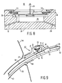
- Figure 9 illustrates a part of a system 37, which is in particular suitable for filling up with fuel.
- An advantageous property of this embodiment is that with an optimal force/travel characteristic only a minimal quantity of air needs to be sucked out of the space 35 (fig. 8), which results in a minimal response time of the converter 18.
- Reference number 38 indicates the part of a vehicle in which a spout 39 is provided, said spout opening into a second tank (not shown). Fuel is transferred from a first tank (not shown), via a filling nozzle 40, to said second tank.
- the regulator 1 is accommodated in the nozzle 40, which regulator 1 mechanically operates, via the command rod 25, the valve 41 accommodated in said nozzle 40.
- the medium valve 41 shuts off the supply of fuel from a fuel pipe 42 to a fuel pipe portion 43.
- the pneumatic converter 18 with the pressure pipes 19 and 20 are diagrammatically illustrated.
- Reference number 21 indicates a portion of the feeler which takes care of it that a flexible part 50 is compressed when the end of the nozzle 40 is inserted in the spout 39, as a result of which the feeler 21 is displaced and the port E in the regulator 1 is moved.
- the converter 18 will stay in its rest position, as a result of which the command rod 25 will move when the control knob 22 is depressed, causing fuel to flow through the pipes 42 and 43.
Landscapes
- Engineering & Computer Science (AREA)
- Physics & Mathematics (AREA)
- General Physics & Mathematics (AREA)
- Automation & Control Theory (AREA)
- Mechanical Engineering (AREA)
- Air Bags (AREA)
- Preliminary Treatment Of Fibers (AREA)
- Control Of Temperature (AREA)
- Fluid-Driven Valves (AREA)
- Mechanically-Actuated Valves (AREA)
- Loading And Unloading Of Fuel Tanks Or Ships (AREA)
- Flow Control (AREA)
- Amplifiers (AREA)
- Fuel-Injection Apparatus (AREA)
- Control Of Metal Rolling (AREA)
Claims (14)
- Multivariabler Regler (1) mit wenigstens 2 mechanisch betätigbaren Einführungen, wobei eine der Einführungen eine Übertragungsfunktion zur anderen Einführung hin hat, einen mechanisch mit jeder der Einführungen verbundenen Körper (2), welcher Körper unter dem Einfluß einer äußeren Kraft beweglich ist, die auf wenigstens eine dieser Einführungen ausgeübt wird, dadurch gekennzeichnet, daß der Regler wenigstens noch zwei andere mechanisch betätigbare Einführungen (E, 27) hat und daß die genannte Funktionsübertragung einen lineare Funktionsübertragung ist und daß der genannte Körper (2) in drei Dimensionen beweglich ist.
- Regler nach Anspruch 1, dadurch gekennzeichnet, daß die mechanische Kupplung zwischen wenigstens drei (C, D, E) der vier mechanischen Einführungen und dem Körper (2) mit Kugelgelenken (7) versehen ist.
- Regler nach einem der Ansprüche 1 - 2, dadurch gekennzeichnet, daß drei der vier Träger der Kraftvektoren der auf die jeweiligen Einführungen auszuübenden Kräfte nahezu in einer Ebene gelegen sind.
- Regler nach Anspruch 3, dadurch gekennzeichnet, daß der Kraftvektor der auf die vierte mechanische Einführung (27) auszuübenden Kraft nahezu senkrecht zu den drei anderen Kraftvektoren steht.
- Regler nach einem oder mehreren der vorigen Ansprüche 1 bis einschließlich 4, dadurch gekennzeichnet, daß der Körper (2) im Regler durch die Ausübung einer Kraft auf eine der Einführungen (C, D, E, 27) über ein labiles Gleichgewicht bewegt werden kann.
- Regler nach Anspruch 5, dadurch gekennzeichnet, daß durch die Ausübung einer Kraft auf die vierte mechanische Einführung (27) der Körper (2) über das labile Gleichgewicht bewegt werden kann.
- Regler nach einem oder mehreren der Ansprüche 1 bis einschließlich 6, dadurch gekennzeichnet, daß der Regler (1) eine Feder (24) aufweist, die derart im Regler angebracht ist, daß diese den Körper in einer stabilen Position zu halten versucht.
- Regler nach Anspruch 7, dadurch gekennzeichnet, daß die Feder (24) in der Weise in dem Regler angebracht ist, daß diese die Ausgangspositionen von zwei aus vier, auf die mechanischen Einführungen (C, D, E, 27) angebrachten Führungs-Stangen (6, 8, 23, 24), bestimmt.
- Regler nach Anspruch 7 oder 8, dadurch gekennzeichnet, daß der Regler (1) mit wenigstens einer Führungsbahn (29) versehen ist, entlang welcher Bahn eine Bewegung des beweglichen Körpers (2) geführt wird.
- Regler nach Anspruch 9, dadurch gekennzeichnet, daß die Führungsbahn (29) derart ausgelegt ist, daß bei der Einnahme unterschiedlicher Positionen durch den Körper (2) nur ein kleiner Abstand überbrückt zu werden braucht, um den Körper über den labilen Gleichgewichtspunkt hinweg zu bewegen.
- Regler nach einem oder mehreren der Ansprüche 1 bis einschließlich 11, dadurch gekennzeichnet, daß der Regler (1) einen mit der vierten mechanischen Einführung (27) gekoppelten pneumatischen Umwandler (18) aufweist, der derart ausgelegt ist, daß bei der Aktivierung des Umwandlers bei kleiner Verstellung der vierten Einführung eine verhältnismäßig große Kraft durch den Umwandler auf die vierte Einführung ausgeübt wird.
- Regler nach Anspruch 11, dadurch gekennzeichnet, daß der pneumatische Umwandler (18) ein, unter dem Einfluß eines subatmosphärischen Druckunterschieds bewegliches Element (34) aufweist, welches Element (34) in einer flexiblen Membran (32) des Umwandlers aufgehängt ist, wobei, bei Bewegung des Elements aus der Ruheposition, ein größer werdender Anteil der durch den Druckunterschied erzeugten Kraft von in dem Umwandler vorgesehenen Mitteln aufgenommen wird, die die fortgehende Bewegung des Elements erschweren.
- Multi-variabler Regler (1) mit wenigstens zwei mechanisch betätigbaren Einführungen, von denen eine eine Übertragungsfunktion zu wenigstens der anderen Einführung hat, und mit einem Körper (13), gekoppelt an jeder der genannten Einführungen, welcher Körper unter dem Einfluß einer äußeren Kraft die auf wenigstens eine der genannten Einführungen ausgeübt wird beweglich ist, dadurch gekennzeichnet, daß der Regler (1) noch wenigstens zwei mechanisch betätigbare Einführungen hat, daß die Übertragungsfunktion eine lineare Übertragungsfunktion ist und daß der Körper aus einem mit Flüssigkeit gefüllten Körper (13) mit als Balge ausgeführten Einführungen (14, 15, 16, 17) besteht, welche Balge unter der Einwirkung daraus auszuübender Kräfte bewegbar sind.
- System, versehen mit multivariablem Regler nach einem oder mehreren der Ansprüche 1 bis einschließlich 13, dadurch gekennzeichnet, daß das System für die Regelung des Transports eines Mediums geeignet ist, von einem ersten zu einem zweiten Tank, und mit einem mit der ersten Einführung (E) gekoppelten Sensor (21) versehen ist, dessen Position der Position entspricht, die eine Zapfpistole gegenüber der Öffnung des zweiten Tanks einnimmt, daß das System mit einer mit der dritten Einführung (D) gekoppelten Absperrvorrichtung (41) versehen ist, um die Absperrvorrichtung in Abhängigkeit von der ersten (E), zweiten (C) und vierten (D) Einführung bedienen zu können, daß das System mit einem mit der zweiten Einführung gekoppelten Bedienungsknopf (22) versehen ist, um den Mediumstransport zu beeinflussen, und daß das System mit einem mit der vierten Einführung (27) gekoppelten pneumatischen Umwandler (18) versehen ist, der der vierten Einführung einen Befehl erteilt, wenn durch einen subatmosphärischen Druckunterschied angegeben wird daß der zweite Tank nahezu voll ist.
Priority Applications (5)
| Application Number | Priority Date | Filing Date | Title |
|---|---|---|---|
| AT90200767T ATE116748T1 (de) | 1990-03-30 | 1990-03-30 | Multivariabler regler mit mindestens vier mechanischen einführungen und system ausgerüstet mit demselben. |
| EP19900200767 EP0450195B1 (de) | 1990-03-30 | 1990-03-30 | Multivariabler Regler mit mindestens vier mechanischen Einführungen und System ausgerüstet mit demselben |
| DE69015804T DE69015804T2 (de) | 1990-03-30 | 1990-03-30 | Multivariabler Regler mit mindestens vier mechanischen Einführungen und System ausgerüstet mit demselben. |
| US07/674,645 US5224524A (en) | 1990-03-30 | 1991-03-22 | Multi-variable regulator having at least four mechanical ports and system provided with such a regulator |
| JP3091179A JPH04227510A (ja) | 1990-03-30 | 1991-03-29 | 多変数レギュレータ |
Applications Claiming Priority (1)
| Application Number | Priority Date | Filing Date | Title |
|---|---|---|---|
| EP19900200767 EP0450195B1 (de) | 1990-03-30 | 1990-03-30 | Multivariabler Regler mit mindestens vier mechanischen Einführungen und System ausgerüstet mit demselben |
Publications (2)
| Publication Number | Publication Date |
|---|---|
| EP0450195A1 EP0450195A1 (de) | 1991-10-09 |
| EP0450195B1 true EP0450195B1 (de) | 1995-01-04 |
Family
ID=8204981
Family Applications (1)
| Application Number | Title | Priority Date | Filing Date |
|---|---|---|---|
| EP19900200767 Expired - Lifetime EP0450195B1 (de) | 1990-03-30 | 1990-03-30 | Multivariabler Regler mit mindestens vier mechanischen Einführungen und System ausgerüstet mit demselben |
Country Status (5)
| Country | Link |
|---|---|
| US (1) | US5224524A (de) |
| EP (1) | EP0450195B1 (de) |
| JP (1) | JPH04227510A (de) |
| AT (1) | ATE116748T1 (de) |
| DE (1) | DE69015804T2 (de) |
Families Citing this family (1)
| Publication number | Priority date | Publication date | Assignee | Title |
|---|---|---|---|---|
| US8997804B2 (en) * | 2011-10-18 | 2015-04-07 | Vapor Systems Technologies, Inc. | Nozzle interlock failsafe/lost motion mechanisms |
Family Cites Families (14)
| Publication number | Priority date | Publication date | Assignee | Title |
|---|---|---|---|---|
| NL88155C (de) * | 1953-02-17 | 1900-01-01 | ||
| US3026905A (en) * | 1958-03-11 | 1962-03-27 | Atlas Copco Ab | Multiple valve devices |
| US3088489A (en) * | 1960-08-22 | 1963-05-07 | Parker Hannifin Corp | Detent release for flow control valves |
| US3113756A (en) * | 1961-05-08 | 1963-12-10 | Lincoln Tool And Machine Co In | Regulator |
| DE1498288C3 (de) * | 1965-06-19 | 1975-08-14 | Robert Bosch Gmbh, 7000 Stuttgart | Regelsystem für konstante hydraulische Leistung |
| DE1300444B (de) * | 1966-09-06 | 1969-07-31 | Westinghouse Bremsen U Appbau | Pneumatisch betaetigbare UEbergabesicherung zwischen zwei oder mehr Steuerstaenden einer umsteuerbaren Antriebsanlage |
| US3637187A (en) * | 1969-05-05 | 1972-01-25 | Daniel Stephen Delany | Valve with axially spaced guides and bellows operator |
| US3809314A (en) * | 1971-10-20 | 1974-05-07 | Barber Colman Co | Self-powered variable volume air damper control |
| GB1497055A (en) * | 1974-06-28 | 1978-01-05 | Simplex Cambridge | Milking machines incorporating control arrangements responsive to liquid flow rate |
| FR2300283A1 (fr) * | 1975-02-04 | 1976-09-03 | Fevre Andre | Dispositif de securite pour remplissage de cuve |
| US4058149A (en) * | 1975-09-02 | 1977-11-15 | Sun Oil Company Of Pennsylvania | Attitude valve for a gasoline dispensing nozzle with a vapor receiving system |
| US4027708A (en) * | 1976-04-01 | 1977-06-07 | Suntech, Inc. | Dispensing nozzle control system |
| DD139479A1 (de) * | 1978-11-14 | 1980-01-02 | Klaus Krueger | Vorrichtung zum steuern von behandlungsmedien und/oder energie fuer maschinen |
| CH639005A5 (fr) * | 1980-12-16 | 1983-10-31 | Nationale Sa | Dispositif pour le controle du melange et du debit de deux fluides. |
-
1990
- 1990-03-30 AT AT90200767T patent/ATE116748T1/de not_active IP Right Cessation
- 1990-03-30 DE DE69015804T patent/DE69015804T2/de not_active Expired - Fee Related
- 1990-03-30 EP EP19900200767 patent/EP0450195B1/de not_active Expired - Lifetime
-
1991
- 1991-03-22 US US07/674,645 patent/US5224524A/en not_active Expired - Lifetime
- 1991-03-29 JP JP3091179A patent/JPH04227510A/ja active Pending
Also Published As
| Publication number | Publication date |
|---|---|
| DE69015804T2 (de) | 1995-06-08 |
| ATE116748T1 (de) | 1995-01-15 |
| DE69015804D1 (de) | 1995-02-16 |
| US5224524A (en) | 1993-07-06 |
| EP0450195A1 (de) | 1991-10-09 |
| JPH04227510A (ja) | 1992-08-17 |
Similar Documents
| Publication | Publication Date | Title |
|---|---|---|
| US5282888A (en) | Holding apparatus for a dip coating apparatus | |
| US5125706A (en) | Article holding apparatus | |
| US4211263A (en) | Dual fill rate liquid filler apparatus having a single control valve | |
| EP0450195B1 (de) | Multivariabler Regler mit mindestens vier mechanischen Einführungen und System ausgerüstet mit demselben | |
| JPH0613986B2 (ja) | 貯蔵液体又は固体原料の量を決定して指示するための方法及び装置 | |
| AU641387B2 (en) | Filling head for aseptically filling a pack | |
| KR20210098532A (ko) | 뚜껑 부재 장착 장치 | |
| US2946196A (en) | Valve mechanism for crane controls | |
| US5107898A (en) | Pressure equalizing system and valve | |
| US6098848A (en) | Method and apparatus for connecting a fluid reservoir with pipelines | |
| EP0675405A2 (de) | Verfahren und Vorrichtung zur Flüssigkeitssteuerung | |
| AU784410B2 (en) | Low capacity chlorine gas feed system | |
| GB2178135A (en) | A controlling device for an intravenous feeding or medicating device | |
| US5322198A (en) | Pump-equipped liquid supply system | |
| EP0235761B1 (de) | Fluidsteuersystem | |
| CN105555703A (zh) | 加注接头 | |
| JP2665439B2 (ja) | 流体充填機用充填バルブ | |
| US3913784A (en) | Sealing closure apparatus | |
| US4773830A (en) | Control apparatus for a gas driven pump | |
| US2710624A (en) | Pressure operated actuating mechanism | |
| CN115799105B (zh) | 半导体设备 | |
| US5546153A (en) | Liquid transfer system and method | |
| KR102847750B1 (ko) | 케미컬 용기의 개폐캡 개폐장치 | |
| JPS6221527B2 (de) | ||
| EP0634326A1 (de) | Füllventil |
Legal Events
| Date | Code | Title | Description |
|---|---|---|---|
| PUAI | Public reference made under article 153(3) epc to a published international application that has entered the european phase |
Free format text: ORIGINAL CODE: 0009012 |
|
| 17P | Request for examination filed |
Effective date: 19900330 |
|
| AK | Designated contracting states |
Kind code of ref document: A1 Designated state(s): AT BE CH DE DK ES FR GB GR IT LI LU NL SE |
|
| K1C1 | Correction of patent application (title page) published |
Effective date: 19911009 |
|
| 17Q | First examination report despatched |
Effective date: 19930916 |
|
| GRAA | (expected) grant |
Free format text: ORIGINAL CODE: 0009210 |
|
| AK | Designated contracting states |
Kind code of ref document: B1 Designated state(s): AT BE CH DE DK ES FR GB GR IT LI LU NL SE |
|
| PG25 | Lapsed in a contracting state [announced via postgrant information from national office to epo] |
Ref country code: IT Free format text: LAPSE BECAUSE OF FAILURE TO SUBMIT A TRANSLATION OF THE DESCRIPTION OR TO PAY THE FEE WITHIN THE PRE;WARNING: LAPSES OF ITALIAN PATENTS WITH EFFECTIVE DATE BEFORE 2007 MAY HAVE OCCURRED AT ANY TIME BEFORE 2007. THE CORRECT EFFECTIVE DATE MAY BE DIFFERENT FROM THE ONE RECORDED.SCRIBED TIME-LIMIT Effective date: 19950104 Ref country code: LI Effective date: 19950104 Ref country code: BE Effective date: 19950104 Ref country code: DK Effective date: 19950104 Ref country code: GR Free format text: LAPSE BECAUSE OF FAILURE TO SUBMIT A TRANSLATION OF THE DESCRIPTION OR TO PAY THE FEE WITHIN THE PRESCRIBED TIME-LIMIT Effective date: 19950104 Ref country code: ES Free format text: THE PATENT HAS BEEN ANNULLED BY A DECISION OF A NATIONAL AUTHORITY Effective date: 19950104 Ref country code: CH Effective date: 19950104 Ref country code: AT Effective date: 19950104 |
|
| REF | Corresponds to: |
Ref document number: 116748 Country of ref document: AT Date of ref document: 19950115 Kind code of ref document: T |
|
| REF | Corresponds to: |
Ref document number: 69015804 Country of ref document: DE Date of ref document: 19950216 |
|
| ET | Fr: translation filed | ||
| PG25 | Lapsed in a contracting state [announced via postgrant information from national office to epo] |
Ref country code: LU Free format text: LAPSE BECAUSE OF NON-PAYMENT OF DUE FEES Effective date: 19950331 |
|
| PG25 | Lapsed in a contracting state [announced via postgrant information from national office to epo] |
Ref country code: SE Effective date: 19950404 |
|
| REG | Reference to a national code |
Ref country code: CH Ref legal event code: PL |
|
| PLBE | No opposition filed within time limit |
Free format text: ORIGINAL CODE: 0009261 |
|
| STAA | Information on the status of an ep patent application or granted ep patent |
Free format text: STATUS: NO OPPOSITION FILED WITHIN TIME LIMIT |
|
| 26N | No opposition filed | ||
| REG | Reference to a national code |
Ref country code: GB Ref legal event code: IF02 |
|
| REG | Reference to a national code |
Ref country code: FR Ref legal event code: ST |
|
| REG | Reference to a national code |
Ref country code: FR Ref legal event code: RN Ref country code: FR Ref legal event code: FC |
|
| PGFP | Annual fee paid to national office [announced via postgrant information from national office to epo] |
Ref country code: NL Payment date: 20080331 Year of fee payment: 19 |
|
| PGFP | Annual fee paid to national office [announced via postgrant information from national office to epo] |
Ref country code: DE Payment date: 20080424 Year of fee payment: 19 |
|
| PGFP | Annual fee paid to national office [announced via postgrant information from national office to epo] |
Ref country code: FR Payment date: 20080418 Year of fee payment: 19 |
|
| PGFP | Annual fee paid to national office [announced via postgrant information from national office to epo] |
Ref country code: GB Payment date: 20080417 Year of fee payment: 19 |
|
| GBPC | Gb: european patent ceased through non-payment of renewal fee |
Effective date: 20090330 |
|
| NLV4 | Nl: lapsed or anulled due to non-payment of the annual fee |
Effective date: 20091001 |
|
| PG25 | Lapsed in a contracting state [announced via postgrant information from national office to epo] |
Ref country code: DE Free format text: LAPSE BECAUSE OF NON-PAYMENT OF DUE FEES Effective date: 20091001 |
|
| PG25 | Lapsed in a contracting state [announced via postgrant information from national office to epo] |
Ref country code: NL Free format text: LAPSE BECAUSE OF NON-PAYMENT OF DUE FEES Effective date: 20091001 |
|
| PG25 | Lapsed in a contracting state [announced via postgrant information from national office to epo] |
Ref country code: GB Free format text: LAPSE BECAUSE OF NON-PAYMENT OF DUE FEES Effective date: 20090330 |
|
| REG | Reference to a national code |
Ref country code: FR Ref legal event code: ST Effective date: 20101130 |
|
| PG25 | Lapsed in a contracting state [announced via postgrant information from national office to epo] |
Ref country code: FR Free format text: LAPSE BECAUSE OF NON-PAYMENT OF DUE FEES Effective date: 20090331 |