EP0449762B1 - Verbraucher-spezifische schraubenförmige Federung einer Schuhsole und Herstellungsverfahren dazu - Google Patents
Verbraucher-spezifische schraubenförmige Federung einer Schuhsole und Herstellungsverfahren dazu Download PDFInfo
- Publication number
- EP0449762B1 EP0449762B1 EP91630007A EP91630007A EP0449762B1 EP 0449762 B1 EP0449762 B1 EP 0449762B1 EP 91630007 A EP91630007 A EP 91630007A EP 91630007 A EP91630007 A EP 91630007A EP 0449762 B1 EP0449762 B1 EP 0449762B1
- Authority
- EP
- European Patent Office
- Prior art keywords
- shoe
- sole cushion
- layout
- construction
- cushion
- Prior art date
- Legal status (The legal status is an assumption and is not a legal conclusion. Google has not performed a legal analysis and makes no representation as to the accuracy of the status listed.)
- Expired - Lifetime
Links
Images

Classifications
-
- A—HUMAN NECESSITIES
- A43—FOOTWEAR
- A43B—CHARACTERISTIC FEATURES OF FOOTWEAR; PARTS OF FOOTWEAR
- A43B13/00—Soles; Sole-and-heel integral units
- A43B13/14—Soles; Sole-and-heel integral units characterised by the constructive form
- A43B13/18—Resilient soles
- A43B13/181—Resiliency achieved by the structure of the sole
- A43B13/182—Helicoidal springs
Definitions
- the present invention relates to a two-part shoe construction, and to a method of assembling it.
- This invention relates more particularly to a novel coil spring system for a shoe featuring a user-specific, customized layout for various areas of the shoe sole, applicable to athletic, working and walking shoes, or to other activities associated with a particular group.
- the prior art includes various shoe constructions in which a spring is applied to a shoe sole for shock absorption and energy return during walking or running. Examples of these designs include that shown in U.S. Pat. No. 4,843,737 to Vorderer, in which two outwardly curved plates having a tensioning spring are placed in the heel of an athletic shoe, to store and return energy to a runner while providing shock absorption.
- U.S. Pat. No. 4,815,221 to Diaz discloses a shoe sole having an energy control system located in a cavity of the sole, which comprises a set of spring strips and an overlying energy absorbing member capable of absorbing impact energy.
- a shoe sole structure comprising a plurality of vertically stacked disc-springs spanning the width and length of the sole to form a honeycomb framework which applies energy to the base of the foot upon release after load compression.
- a spring boot for bouncing and exercise is disclosed in U.S. Patent No. 4,660,299 to Omilusik, wherein a set of four coil springs is attached to the underside of a boot.
- U.S. Patent 4,506,460 to Rudy describes a spring-type moderator in combination with an air-cushioned sole in an athletic shoe providing improved shock absorption and energy return.
- a hopping and dancing shoe is described in U.S. Patent 4,457,084 to Horibata, et. al., comprising a shoe sole and two coil springs attached on its underside by bolts and nuts.
- U.S. Pat. 4,196,903 to Illustrato discloses a pair of jog-springs attached to the underside of a shoe sole providing a soft, bouncing action in use.
- U.S. Pat. 3,777,374 to Hendricks a pleasure shoe is disclosed having a compression spring unit fitted into a shoe heel for providing shock absorption.
- a shoe having a sole element provided with bores for retaining resilient means such as spring elements is disclosed in U.S. Patent 2,710,460 to Stasinos.
- a cushioned shoe sole is disclosed comprising a cushioning layer composed of resilient material with coil springs molded therein, and placed between top and bottom facing sheets.
- EP-A-0 215 491 discloses a cushioning assembly located in the rear part of the shoe, the assembly comprising a plurality of coil springs positioned between the outer sole and the shoe upper, the springs being adjustable and/or replaceable by access to the outer sole which come into contact with the ground.
- the two-part shoe construction provides a system for absorbing shocks and returning energy in the shoe sole, the system comprising a flexible sole cushion having formed on an upper side thereof, a plurality of recesses, and a layout of resilient members over the area of said flexible sole cushion, the layout providing shock absorption and energy return upon compression in accordance with a predetermined distribution pattern, the shoe body having a sealed bottom surface.
- the feet and particularly the soles of the feet, carry the entire body weight.
- the many shoe sole constructions found in the market absorb only a small portion of the shock caused as the shoe contacts the floor, and shocks which are not absorbed cause damage to the body. This occurs in the soles of the feet, which have many bones and many jointed surfaces, and in the knees which have fine meniscuses stabilizing the joints and permitting smooth movement.
- the spinal cord is built from many vertebrae, with discs between them which are very sensitive to changes, and which permit bending and straightening of the body. Over a long period of walking, the beating and shocks imparted to the soles of the feet may cause stress fractures in the legs.
- shocks cause changes in the structure of the vertebrae, affecting the discs between them by making them thin and irregular due to friction, so that they lose their flexibility. This damage causes limited movement and flexibility for the entire length of the spinal cord, leading to neck and shoulder pain, poor blood circulation, and stability problems.
- the two-part shoe construction of the invention is characterized by the features claimed in the characterizing part of claim 1.
- the layout comprises a plurality of coil springs, each of the coil springs being seated within one of the recesses, the predetermined distribution pattern being established in relation to a stiffness characteristic associated with each of the coil springs.
- the shoe sole comprises a cover strip overlaying the said flexible sole cushion and the coil springs to form a sealed unit.
- the sealed unit is removably insertable into a hollow base compartment in the shoe body via an opening in the shoe body, enabling replacement of the sealed unit with another and allowing variation of the coil spring layout and the predetermined distribution pattern.
- the shoe sole coil spring system is a customized layout of individual coil springs which are seated in a shoe sole cushion having prefabricated circular depressions on its surface.
- the coil spring system layout and stiffness characteristics may be customized to serve the needs of different users and different applications. For example, depending on the weight of the user, a given shoe size may be fitted with a greater or lesser quantity of springs with different levels of stiffness, or the layout may be a combination of levels. The result is a shock absorption distribution pattern and energy return system for the shoe sole cushion to suit the requirements of the particular application.
- the inventive shoe sole cushion design enables various problems to be addressed, including posture and balance, weakness and paralysis in the lower extremities, distortion in the vertebrae, hunchback, lordosis, fallen arches, etc. Stress fractures in the legs can be reduced.
- the customized layout may be implemented originally during shoe assembly, or it may be achieved by opening the shoe sole cushion and establishing a particular coil spring system layout at the point of sale.
- the second approach is made possible by a novel shoe sole cushion construction which permits opening and reclosing of the sole cushion for purposes of changing the spring system layout.
- Variations in the shoe sole cushion construction enable it to be used in several ways, such as by attachment under the shoe base, inserted via a slot formed in the base, or as a shoe pad.
- Another feature of the invention is the provision of rounded tip or flat plugs for placement into the coil springs at their upper ends to give a textured or smooth finish to the shoe sole cushion.
- the rounded tip plugs are useful in enabling the practice of non-conventional medical technologies, such as reflexology, in specific cases, to stimulate the soles of the feet.
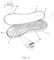
- Shoe 11 has a sole cushion 12 which is typically made of a flexible material, such as rubber, and is provided with a set of circular depressions or recesses 14 over its length and width. Each of recesses 14 may be filled with a suitably shaped filler material such as a rubber disc, which can be removed by prying loose from a given recess 14.
- a set of coil springs 16 (Fig. 2) is provided for placement in recesses 14, and a customized layout of coil springs 16 may be developed by use of appropriate ones of recesses 14.
- a cover layer 17 is attached at the upper edges of sole cushion 12 to enclose the coil spring system 10.
- the user benefits from a shock absorption distribution pattern and energy return system provided in accordance with the customized coil spring system 10 layout.
- coil spring system 10 may use springs having a higher stiffness in this area, i.e. a greater spring constant, to aid a user in maintaining proper posture. This may be accomplished by providing the springs in this area with approximately 25% greater stiffness than those in the remaining areas of sole cushion 12.
- a typical coil spring arrangement in which a plug 18, typically made of plastic, is provided for seating within coil spring 16 itself at either end.
- the lengths of plugs 18 are designed such that their opposite ends do not contact one another when spring 16 is compressed.
- Plug 18 has a flat head, while another type plug 19 has a rounded tip.
- Each of plugs 18, 19 is shaped with a shoulder against which an end of spring 16 rests. As described further herein, while the flat head of plug 18 is normally used in system 10, rounded tip plug 19 may be used for specific requirements relating to foot stimulation.
- the inventive coil spring system 10 layout may be adapted for many applications, including walking, dancing, running or jumping in sports applications, for use in hiking shoes, in weight-bearing work shoes, or for use in a reflexology technique to apply pressure points for foot stimulation in specific areas.
- Each of these applications requires a particular solution since each creates different pressures on different areas of the foot, or no pressure at all. These differences must be expressed in relation to the body weight, that is, in order to provide a comfortable solution to different users, even though they may have the same size foot.
- the springs 16 used may have a spring constant K, and for body weight of 80-100 kg, a spring constant K1 may be used, while for a body weight of 100-120 kg, a spring constant K2 may be used, wherein the spring constants follow the relation: K ⁇ K1 ⁇ K2.
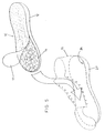
- FIG. 3 there is shown a perspective view of an alternative embodiment of the coil spring system 10 layout of Fig. 1, featuring a reclosable sole construction enabling layout changes.
- shoe sole cushion 12 is provided with a contoured rib 20 integrally formed therewith and extending around its circumference, which is fabricated of the same flexible material as sole cushion 12.
- Cover layer 17 is provided as the bottom surface of the upper portion of shoe 11, and has formed about its circumference a groove 22 shaped so as to engage contoured rib 20 when pressed therein, enabling coil spring system 10 to be closed by attaching cover layer 17 to sole cushion 12.
- shoe sole cushion 12 By prying contoured rib 20 out of groove 22, shoe sole cushion 12 may be opened, so that the customized layout of coil spring system 10 may be changed.
- the shock distribution pattern and energy return system provided by shoe sole cushion 12 may be adjusted at the point of sale to suit the above-described user applications. That is, by opening of shoe sole cushion 12 and addition or removal of coil springs 16 or variation in their layout, the requirements of different applications can be addressed. Reclosing sole cushion 12 is easily achieved by pressing contoured rib 20 into groove 22 of shoe 11.
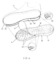
- FIG. 4 another alternative embodiment of the coil spring system 10 layout of Figs. 1 and 3 is shown in perspective, featuring a reclosable sole cushion construction which is removable from shoe 11 for making layout changes.
- sole cushion 12 is fitted within a hollow base compartment 24 of shoe 11, via a slotted opening 26 in shoe wall 27.
- a pair of contoured ribs 20 and grooves 22 are provided respectively on the outer edge 28 of sole cushion 12, and on the upper and lower edges of slotted opening 26.
- cover layer 17 is placed over sole cushion 12 and it is fitted within base compartment 24, ribs 20 and grooves 22 can be used to lock sole cushion 12 in position.
- a particular advantage of this embodiment is the possibility of having a plurality of pre-designed customized layouts of coil spring system 10 in individual sole cushions 12, each available for immediate use in a particular group of applications.
- a user could purchase a shoe and specify a particular application, i.e., walking, sports, or dancing, which is then matched with a pre-designed customized layout.
- the appropriate shoe sole cushion 12 is then selected and inserted into base compartment 24 of shoe 11, wherein it is locked in position. If adjustments are needed, the shoe sole cushion 12 can be removed through slotted opening 26, and cover layer 17 may be opened for making changes in the layout.
- Another possible approach is the provision of a prescription from an orthopedist or podiatrist which specifies the areas of the sole cushion 12 which are to be treated by the beneficial effects of the customized layout, including the necessary spring characteristics, etc.
- the user could present the prescription to the vendor of the inventive shoe sole cushion 12 design, who could then implement the appropriate customized layout.
- sole cushion 12 is arranged as a shoe pad design, which can be removably inserted in shoe 11.
- shoe 11 is manufactured with a sealed bottom surface such as rubber, but without a sole cushion 12, and hollow base compartment 24 is adapted to allow push-fit insertion of sole cushion 12 therein.
- Shoe 11 then completely encloses sole cushion 12 without need for further closure means, and shoe walls 27 maintain it fixed in position.
- a contoured pull strap (not shown) may be attached at the end of sole cushion 12, and tucked against the shoe heel wall, for easy removal.
- a particular advantage of this approach is that as the shoe pad design of sole cushion 12 is worn, it adjusts itself to the contour of the foot, becoming more comfortable. This comfort may be transferred by removing sole cushion 12 from one shoe 11 and inserting it in a new shoe body which replaces a worn-out one. This achieves a cost savings as well, since only a new shoe body must be purchased, and a used sole cushion 12 can be inserted therein.
- a user may choose to purchase several different sole cushions 12 for each of shoes 11, so that different customized layouts of coil spring system 10 may be applied in accordance with different intended applications, as described.
- the inventive coil spring system and shoe sole cushion design minimizes various shock absorption problems of the feet and legs, including those leading to stress fractures and other damage related to specific user applications.
Landscapes
- Footwear And Its Accessory, Manufacturing Method And Apparatuses (AREA)
- Carbon And Carbon Compounds (AREA)
- Springs (AREA)
Claims (17)
- Zweiteilige Schuhkonstruktion, bestehend aus einem Schuhoberteil (11) und einer Schuhsohle, wobei die zweiteilige Schuhkonstruktion ein System (10) zur Stoßdämpfung und zur Energierückführung in der Schuhsohle bildet, wobei dieses System umfaßt:
ein flexibles Sohlenpolster (12), in dessen oberer Seite mehrere Ausnehmungen (14) gebildet sind,
eine Anordnung von elastischen Teilen (16) über dem Bereich des flexiblen Sohlenpolsters (12), wobei die Anordnung die Stoßdämpfung und Energierückführung bei Zusammenpressung gemäß einem vorbestimmten Verteilungsmuster bewirkt, und
das Schuhoberteil (11) mit einer abgedichteten unteren Oberfläche,
dadurch gekennzeichnet, daß die Anordnung mehrere Schraubenfedern (16) umfaßt, wobei jede Schraubenfeder (16) in einer der Ausnehmungen (14) sitzt, wobei das vorbestimmte Verteilungsmuster relativ zu einer Steifheitscharakteristik, welche jeder Schraubenfeder (16) zugeordnet ist, festgelegt wird, und daß die Schuhsohle einen Deckstreifen (17) umfaßt, welcher über dem flexiblen Sohlenpolster (12) und den Schraubenfedern (16) liegt, um eine abgedichtete Einheit (12, 17) zu bilden,
wobei die abgedichtete Einheit (12, 17) entfernbar in eine hohle Bodenkammer (24) in dem Schuhoberteil (11) über eine Öffnung in dem Schuhoberteil (11) einsetzbar ist, was das Ersetzen der abgedichteten Einheit (12, 17) durch eine andere ermöglicht und eine Variation der Schraubenfederanordnung und des vorbestimmten Verteilungsmusters gestattet. - Konstruktion nach Anspruch 1, dadurch gekennzeichnet, daß die mehreren Schraubenfedern (16) variierende Steifheitscharakteristiken jeweils relativ zu ihrer zugeordneten Federkonstante haben.
- Konstruktion nach Anspruch 1, dadurch gekennzeichnet, daß der Deckstreifen (17) an dem flexiblen Sohlenpolster (12) in trennbarer Weise befestigt ist, um so Zugang zu der Schraubenfederanordnung zur Vornahme von Änderungen derselben gemäß benutzerspezifischen Erfordernissen zu ermöglichen.
- Konstruktion nach Anspruch 3, dadurch gekennzeichnet, daß der Deckstreifen (17) mit einer Rippe (20) versehen ist, die sich um seinen Umfang erstreckt, und daß das flexible Sohlenpolster (12) mit einer Nut (22) versehen ist, die in seinem äußeren Umfang gebildet ist, wobei die Rippe (20) lösbar in die Nut (22) zum Befestigen des Deckstreifens (17) an dem flexiblen Sohlenpolster (12) einsetzbar ist.
- Konstruktion nach Anspruch 1, dadurch gekennzeichnet, daß die abgedichtete Einheit (12, 17) in die hohle Bodenkammer (24) durch eine Schlitzöffnung (26) in dem Schuhoberteil (11) lösbar einsetzbar ist.
- Konstruktion nach Anspruch 5, dadurch gekennzeichnet, daß die abgedichtete Einheit (12, 17) an einem äußeren Rand (28) einen Satz Nuten (22) hat, in die an der Schlitzöffnung (26) vorgesehene Rippen (20) einsetzbar sind, um die abgedichtete Einheit (12, 17) in ihrer Position zu verriegeln.
- Konstruktion nach Anspruch 1, dadurch gekennzeichnet, daß in jeder Schraubenfeder (16) an einem Ende derselben ein im wesentlichen zylindrischer Stopfen (18) darin befestigt ist, der mit einer Schulter versehen ist, auf der das Schraubenfederende ruht.
- Konstruktion nach Anspruch 7, dadurch gekennzeichnet, daß der Stopfen (18) einen flachen Kopf hat.
- Konstruktion nach Anspruch 7, dadurch gekennzeichnet, daß der Stopfen (18) eine gerundete Spitze (19) hat, um eine Stimulation eines besonderen Bereiches des Fußes zu bewirken.
- Konstruktion nach Anspruch 1, dadurch gekennzeichnet, daß der Deckstreifen (17) mit einer Umfangsrippe (20) versehen ist, die sich um seinen Umfang erstreckt und lösbar in einer Nut (22) einsetzbar ist, welche an dem Umfang des flexiblen Sohlenpolsters (12) zur Befestigung des Deckstreifens (17) an dem flexiblen Sohlenpolster (12) gebildet ist, wodurch Zugang zu der Schraubenfederanordnung zur Vornahme von Änderungen daran gemäß benutzerspezifischen Erfordernissen gestattet wird.
- Konstruktion nach Anspruch 10, dadurch gekennzeichnet, daß die abgedichtete Einheit (12, 17) in die hohle Bodenkammer (24) über eine Schlitzöffnung (26) in dem Schuhoberteil (11) lösbar einsetzbar ist.
- Konstruktion nach Anspruch 10, dadurch gekennzeichnet, daß die abgedichtete Einheit (12, 17) in die hohle Bodenkammer (24) über die obere Öffnung des Schuhoberteils (11) lösbar einsetzbar ist.
- Verfahren zum Zusammensetzen der zweiteiligen Schuhkonstruktion nach Anspruch 1, um individuelles Einstellen des zur Stoßdämpfung und Energierückführung entworfenen Schraubenfedersystems in der Schuhsohle gemäß benutzerspezifischen Erfordernissen zu ermöglichen, gekennzeichnet durch die Schritte:
Entfernen des Schuhsohlenpolsters (12) aus der hohlen Bodenkammer (24) des Schuhoberteils (11),
Trennen der Deckschicht (17), welche über dem Schraubenfedersystem in dem Schuhsohlenpolster liegt und dieses umschließt, von dem Schuhsohlenpolster (12),
Einstellen von wenigstens der Anordnung oder der Steifheit der Schraubenfedern (16) in dem geöffneten Schuhsohlenpolster (12), um es so individuell einzustellen,
Wiederanbringen der Deckschicht (17) auf dem individuell eingestellten Schuhsohlenpolster (12), und
Wiedereinführen des individuell eingestellten Schuhsohlenpolsters (12) in das Schuhoberteil (11). - Verfahren nach Anspruch 13, dadurch gekennzeichnet, daß die Schritte Entfernen und Wiedereinführen des Schuhsohlenpolsters durch Öffnen eines in der Bodenkammer (24) des Schuhoberteils (11) ausgebildeten Schlitzes (26) und Hindurchführen des Schuhpolsters (12) dadurch ausgeführt werden.
- Verfahren nach Anspruch 13, dadurch gekennzeichnet, daß die Schritte Entfernen und Wiedereinführen des Schuhsohlenpolsters durch Ziehen bzw. Drücken des Schuhsohlenpolsters (12) durch die obere Öffnung in dem Schuhoberteil (11) ausgeführt werden.
- Verfahren nach Anspruch 13, dadurch gekennzeichnet, daß der Schritt Entfernen der Deckschicht durch Entfernen einer an dem Umfangsrand (28) des Schuhsohlenpolsters (12) ausgebildeten Rippe (20) aus einer in dem Umfang der Deckschicht (17) gebildeten Nut (22) ausgeführt wird.
- Verfahren nach Anspruch 13, dadurch gekennzeichnet, daß der Schritt Wiederanbringen der Deckschicht durch Pressen einer an dem Umfangsrand (28) des Schuhsohlenpolsters (12) gebildeten Rippe (20) in eine in dem Umfang der Deckschicht (17) gebildete Nut (22) geführt wird.
Applications Claiming Priority (2)
| Application Number | Priority Date | Filing Date | Title |
|---|---|---|---|
| US07/472,268 US5042175A (en) | 1990-01-30 | 1990-01-30 | User-specific shoe sole coil spring system and method |
| US472268 | 1990-01-30 |
Publications (2)
| Publication Number | Publication Date |
|---|---|
| EP0449762A1 EP0449762A1 (de) | 1991-10-02 |
| EP0449762B1 true EP0449762B1 (de) | 1995-09-20 |
Family
ID=23874810
Family Applications (1)
| Application Number | Title | Priority Date | Filing Date |
|---|---|---|---|
| EP91630007A Expired - Lifetime EP0449762B1 (de) | 1990-01-30 | 1991-01-24 | Verbraucher-spezifische schraubenförmige Federung einer Schuhsole und Herstellungsverfahren dazu |
Country Status (7)
| Country | Link |
|---|---|
| US (1) | US5042175A (de) |
| EP (1) | EP0449762B1 (de) |
| AT (1) | ATE128010T1 (de) |
| CA (1) | CA2034780A1 (de) |
| DE (1) | DE69113092T2 (de) |
| ES (1) | ES2080933T3 (de) |
| IL (1) | IL95830A (de) |
Families Citing this family (85)
| Publication number | Priority date | Publication date | Assignee | Title |
|---|---|---|---|---|
| US5572804A (en) * | 1991-09-26 | 1996-11-12 | Retama Technology Corp. | Shoe sole component and shoe sole component construction method |
| JP3471011B2 (ja) * | 1991-09-26 | 2003-11-25 | スカイデックス・テクノロジーズ・インコーポレーテッド | 靴のソール構成要素 |
| DE4200362C2 (de) * | 1992-01-09 | 1994-06-09 | Bauerfeind Gmbh | Einlegesohle |
| US5343636A (en) * | 1993-05-24 | 1994-09-06 | Albert Sabol | Added footwear to increase stride |
| US5918384A (en) | 1993-08-17 | 1999-07-06 | Akeva L.L.C. | Athletic shoe with improved sole |
| US5513448A (en) * | 1994-07-01 | 1996-05-07 | Lyons; Levert | Athletic shoe with compression indicators and replaceable spring cassette |
| US7540099B2 (en) | 1994-08-17 | 2009-06-02 | Akeva L.L.C. | Heel support for athletic shoe |
| US5753061A (en) * | 1995-06-05 | 1998-05-19 | Robert C. Bogert | Multi-celled cushion and method of its manufacture |
| US6305100B1 (en) | 1995-06-07 | 2001-10-23 | Eugene Komarnycky | Shoe ventilation |
| US5671552A (en) * | 1995-07-18 | 1997-09-30 | Pettibone; Virginia G. | Atheletic shoe |
| US5806210A (en) | 1995-10-12 | 1998-09-15 | Akeva L.L.C. | Athletic shoe with improved heel structure |
| USD397236S (en) | 1996-04-24 | 1998-08-25 | Wilmot Elizabeth C | Translucent covered multi point foot support for footwear |
| DE19621705B4 (de) * | 1996-05-30 | 2007-04-12 | Alexander Schneider | Einlegesohle, insbesondere für Sport- und Orthopädieschuhe |
| USD399040S (en) | 1996-07-24 | 1998-10-06 | L'article Chaussant Europeen | Shoe sole |
| US5845419A (en) * | 1997-09-23 | 1998-12-08 | Begg; John | Spring overshoe |
| US6029962A (en) | 1997-10-24 | 2000-02-29 | Retama Technology Corporation | Shock absorbing component and construction method |
| US5956869A (en) * | 1998-03-06 | 1999-09-28 | Energaire Corporation | Shoe sole construction with mesh liner for mid-sole cavity |
| IL126916A0 (en) | 1998-11-05 | 1999-09-22 | Springco Ltd | Shock-absorbing insole |
| US7334350B2 (en) | 1999-03-16 | 2008-02-26 | Anatomic Research, Inc | Removable rounded midsole structures and chambers with computer processor-controlled variable pressure |
| US7010869B1 (en) | 1999-04-26 | 2006-03-14 | Frampton E. Ellis, III | Shoe sole orthotic structures and computer controlled compartments |
| AU4661400A (en) | 1999-04-26 | 2000-11-10 | Ellis, Frampton E. | Shoe sole orthotic structures and computer controlled compartments |
| US6138383A (en) * | 1999-08-09 | 2000-10-31 | Steinke; Richard A. | Shoe insert |
| US7016867B2 (en) | 2000-03-10 | 2006-03-21 | Lyden Robert M | Method of conducting business including making and selling a custom article of footwear |
| US7107235B2 (en) | 2000-03-10 | 2006-09-12 | Lyden Robert M | Method of conducting business including making and selling a custom article of footwear |
| US6601042B1 (en) * | 2000-03-10 | 2003-07-29 | Robert M. Lyden | Customized article of footwear and method of conducting retail and internet business |
| US7752775B2 (en) | 2000-03-10 | 2010-07-13 | Lyden Robert M | Footwear with removable lasting board and cleats |
| USD447330S1 (en) | 2001-03-08 | 2001-09-04 | Nike, Inc. | Portion of a shoe sole |
| USD446387S1 (en) | 2001-03-08 | 2001-08-14 | Nike, Inc. | Portion of a shoe sole |
| USD446923S1 (en) | 2001-03-08 | 2001-08-28 | Nike, Inc. | Portion of a shoe sole |
| JP4020664B2 (ja) | 2001-05-11 | 2007-12-12 | 株式会社アシックス | 緩衝構造を備えたミッドソール |
| US6393731B1 (en) | 2001-06-04 | 2002-05-28 | Vonter Moua | Impact absorber for a shoe |
| US6622401B2 (en) * | 2001-07-18 | 2003-09-23 | Carroll, Iii Lester Erwin | Modified oxford shoe providing vertical and horizontal heel pressure diminishment including an optional means of adjusting pronation |
| US6446267B1 (en) * | 2001-09-27 | 2002-09-10 | Mrugesh K. Shah | Protective sock and shoe lining |
| US6964120B2 (en) | 2001-11-02 | 2005-11-15 | Nike, Inc. | Footwear midsole with compressible element in lateral heel area |
| US6851204B2 (en) | 2001-11-15 | 2005-02-08 | Nike, Inc. | Footwear sole with a stiffness adjustment mechanism |
| US6898870B1 (en) | 2002-03-20 | 2005-05-31 | Nike, Inc. | Footwear sole having support elements with compressible apertures |
| US20030200677A1 (en) * | 2002-04-26 | 2003-10-30 | Abraham Carl J. | Enhanced impact and energy absorbing product for footwear, protective equipment, floors, boards, walls, and other surfaces |
| US20030217483A1 (en) * | 2002-05-24 | 2003-11-27 | Abraham Carl J. | Enhanced impact and energy absorbing product for footwear, protective equipment, floors, boards, walls, and other surfaces |
| US20040016148A1 (en) * | 2002-07-23 | 2004-01-29 | Chen Huan Li | Elastic shoe-pad |
| US6820353B2 (en) * | 2002-07-26 | 2004-11-23 | Oakley, Inc. | Performance shoe midsole |
| US20050028402A1 (en) * | 2002-07-31 | 2005-02-10 | Miller Ernest D. | Micro-support cushioning system |
| US7415782B2 (en) * | 2002-12-05 | 2008-08-26 | Carroll Iii Lester Erwin | Shoe providing vertical/horizontal heel pressure diminishment |
| US7082698B2 (en) | 2003-01-08 | 2006-08-01 | Nike, Inc. | Article of footwear having a sole structure with adjustable characteristics |
| US6951066B2 (en) * | 2003-07-01 | 2005-10-04 | The Rockport Company, Llc | Cushioning sole for an article of footwear |
| US6931766B2 (en) * | 2003-11-12 | 2005-08-23 | Nike, Inc. | Footwear with a separable foot-receiving portion and sole structure |
| ITRM20040573A1 (it) * | 2004-11-23 | 2005-02-23 | Ks Italia S A S Di Ambrosone M | Plantare per stimolazione propriocettiva, esterocettiva, pressocettiva e/0 reflessogena. |
| US7475497B2 (en) | 2005-01-18 | 2009-01-13 | Nike, Inc. | Article of footwear with a perforated midsole |
| US7493708B2 (en) | 2005-02-18 | 2009-02-24 | Nike, Inc. | Article of footwear with plate dividing a support column |
| US7726042B2 (en) * | 2005-03-23 | 2010-06-01 | Meschan David F | Athletic shoe with removable resilient element |
| US7401418B2 (en) | 2005-08-17 | 2008-07-22 | Nike, Inc. | Article of footwear having midsole with support pillars and method of manufacturing same |
| WO2007060500A2 (en) * | 2005-11-22 | 2007-05-31 | Neuroreflex Ltd. | Plantar for reflexological stimulation |
| US7748141B2 (en) | 2006-05-18 | 2010-07-06 | Nike, Inc | Article of footwear with support assemblies having elastomeric support columns |
| US20080010868A1 (en) * | 2006-07-13 | 2008-01-17 | Hsin-I Plastic Co., Ltd. | Footwear having cushioning device |
| US20080163410A1 (en) * | 2007-01-05 | 2008-07-10 | Wilson Sporting Goods Co. | Shock-absorbing facemask attachment assembly |
| USD576780S1 (en) * | 2007-05-16 | 2008-09-16 | C. & J. Clark America, Inc. | Shoe insole with bumps |
| US8726424B2 (en) | 2010-06-03 | 2014-05-20 | Intellectual Property Holdings, Llc | Energy management structure |
| US8646191B2 (en) | 2010-08-13 | 2014-02-11 | Nike, Inc. | Sole assembly for article of footwear exhibiting posture-dependent characteristics |
| US8881428B2 (en) | 2010-09-02 | 2014-11-11 | Nike, Inc. | Sole assembly for article of footwear with plural cushioning members |
| GB201015073D0 (en) * | 2010-09-10 | 2010-10-27 | Harrison Spinks Beds Ltd | Resilient pad for footwear |
| US20120192451A1 (en) * | 2011-01-29 | 2012-08-02 | Kazumi Fujikura | Fitness insole |
| USD679058S1 (en) | 2011-07-01 | 2013-03-26 | Intellectual Property Holdings, Llc | Helmet liner |
| US9516910B2 (en) | 2011-07-01 | 2016-12-13 | Intellectual Property Holdings, Llc | Helmet impact liner system |
| USD683079S1 (en) | 2011-10-10 | 2013-05-21 | Intellectual Property Holdings, Llc | Helmet liner |
| US9204680B2 (en) | 2011-11-18 | 2015-12-08 | Nike, Inc. | Footwear having corresponding outsole and midsole shapes |
| US9320311B2 (en) | 2012-05-02 | 2016-04-26 | Intellectual Property Holdings, Llc | Helmet impact liner system |
| US9894953B2 (en) | 2012-10-04 | 2018-02-20 | Intellectual Property Holdings, Llc | Helmet retention system |
| US10645995B2 (en) | 2013-01-11 | 2020-05-12 | Nike, Inc. | Method of making and article of footwear formed with gas-filled pockets or chambers |
| US20150047224A1 (en) * | 2013-08-16 | 2015-02-19 | Jing Zhao | Shoe having carbon fiber composite spring soles and upper support |
| USD733972S1 (en) | 2013-09-12 | 2015-07-07 | Intellectual Property Holdings, Llc | Helmet |
| US9498018B2 (en) * | 2013-09-30 | 2016-11-22 | Arye Binder | High heel shoe |
| US9743701B2 (en) | 2013-10-28 | 2017-08-29 | Intellectual Property Holdings, Llc | Helmet retention system |
| US20160286905A1 (en) * | 2013-11-15 | 2016-10-06 | Nike, Inc. | Article of footwear having ground surface material accumulation prevention structure |
| US9538813B1 (en) | 2014-08-20 | 2017-01-10 | Akervall Technologies, Inc. | Energy absorbing elements for footwear and method of use |
| WO2016153501A1 (en) * | 2015-03-25 | 2016-09-29 | Binder Arye | Improved high heel shoe |
| US10709201B2 (en) * | 2015-09-11 | 2020-07-14 | Nike, Inc. | Pin array adaptive wedge |
| US10842223B2 (en) * | 2016-01-15 | 2020-11-24 | Nike, Inc. | Footwear with internal chassis and/or indexed sock liner |
| US10032202B2 (en) * | 2016-02-26 | 2018-07-24 | Nike, Inc. | Method of custom manufacturing footwear according to a cycle |
| US10582740B2 (en) * | 2016-02-26 | 2020-03-10 | Nike, Inc. | Method of customizing stability in articles of footwear |
| US10117478B2 (en) * | 2016-02-26 | 2018-11-06 | Nike, Inc. | Method of customizing heel cushioning in articles of footwear |
| USD825167S1 (en) * | 2017-03-26 | 2018-08-14 | Chi-Yuan Chang | Pneumatic insole |
| USD869137S1 (en) * | 2017-12-20 | 2019-12-10 | Crocs, Inc. | Footwear |
| USD860616S1 (en) * | 2018-05-29 | 2019-09-24 | DFO Global Performance Commerce Limited | Insole |
| US11399591B2 (en) | 2020-03-16 | 2022-08-02 | Robert Lyden | Article of footwear, method of making the same, and method of conducting retail and internet business |
| US12178288B2 (en) | 2020-03-16 | 2024-12-31 | Robert Lyden | Article of footwear, method of making the same, and method of conducting retail and internet business |
| US20220142297A1 (en) * | 2020-11-09 | 2022-05-12 | National Taiwan University Of Science And Technology | Shoe midsole with variable dimension helical spring made by additive manufacturing process |
Citations (2)
| Publication number | Priority date | Publication date | Assignee | Title |
|---|---|---|---|---|
| EP0215491A1 (de) * | 1985-09-20 | 1987-03-25 | Marco A. Dr. Scatena | Federelastische Anordnung für Schuhe |
| EP0299669A2 (de) * | 1987-07-09 | 1989-01-18 | Hi-Tec Sports Plc | Sport- oder Freizeitschuh mit stossdämpfender Sohle |
Family Cites Families (12)
| Publication number | Priority date | Publication date | Assignee | Title |
|---|---|---|---|---|
| US2437227A (en) * | 1947-03-05 | 1948-03-02 | Hall Manville | Cushioned shoe sole |
| US3351353A (en) * | 1965-03-12 | 1967-11-07 | Dorothea M Weitzner | Retractable roller and ice skates for shoes |
| US3777374A (en) * | 1972-07-19 | 1973-12-11 | L Hendricks | Pleasure shoe |
| US4196903A (en) * | 1978-04-10 | 1980-04-08 | Illustrato Vito J | Jog-springs |
| US4377042A (en) * | 1979-07-30 | 1983-03-22 | Peter Bauer | Footwear having removable sole |
| US4506460A (en) * | 1982-06-18 | 1985-03-26 | Rudy Marion F | Spring moderator for articles of footwear |
| US4805319A (en) * | 1985-02-26 | 1989-02-21 | Kangaroos U.S.A., Inc. | Cushioning and impact absorptive means for footwear operative component |
| US4715130A (en) * | 1985-09-20 | 1987-12-29 | Alessandro Scatena | Cushion system for shoes |
| US4660299A (en) * | 1986-01-13 | 1987-04-28 | Dale Omilusik | Spring boot |
| US4774774A (en) * | 1986-05-22 | 1988-10-04 | Allen Jr Freddie T | Disc spring sole structure |
| US4815221A (en) * | 1987-02-06 | 1989-03-28 | Reebok International Ltd. | Shoe with energy control system |
| US4843737A (en) * | 1987-10-13 | 1989-07-04 | Vorderer Thomas W | Energy return spring shoe construction |
-
1990
- 1990-01-30 US US07/472,268 patent/US5042175A/en not_active Expired - Fee Related
- 1990-09-27 IL IL95830A patent/IL95830A/xx not_active IP Right Cessation
-
1991
- 1991-01-23 CA CA002034780A patent/CA2034780A1/en not_active Abandoned
- 1991-01-24 EP EP91630007A patent/EP0449762B1/de not_active Expired - Lifetime
- 1991-01-24 AT AT91630007T patent/ATE128010T1/de not_active IP Right Cessation
- 1991-01-24 DE DE69113092T patent/DE69113092T2/de not_active Expired - Fee Related
- 1991-01-24 ES ES91630007T patent/ES2080933T3/es not_active Expired - Lifetime
Patent Citations (2)
| Publication number | Priority date | Publication date | Assignee | Title |
|---|---|---|---|---|
| EP0215491A1 (de) * | 1985-09-20 | 1987-03-25 | Marco A. Dr. Scatena | Federelastische Anordnung für Schuhe |
| EP0299669A2 (de) * | 1987-07-09 | 1989-01-18 | Hi-Tec Sports Plc | Sport- oder Freizeitschuh mit stossdämpfender Sohle |
Also Published As
| Publication number | Publication date |
|---|---|
| ES2080933T3 (es) | 1996-02-16 |
| IL95830A0 (en) | 1991-06-30 |
| EP0449762A1 (de) | 1991-10-02 |
| ATE128010T1 (de) | 1995-10-15 |
| DE69113092T2 (de) | 1996-05-15 |
| IL95830A (en) | 1993-07-08 |
| DE69113092D1 (de) | 1995-10-26 |
| US5042175A (en) | 1991-08-27 |
| CA2034780A1 (en) | 1991-07-31 |
Similar Documents
| Publication | Publication Date | Title |
|---|---|---|
| EP0449762B1 (de) | Verbraucher-spezifische schraubenförmige Federung einer Schuhsole und Herstellungsverfahren dazu | |
| CA2630817C (en) | Devices with internal flexibility sipes, including siped chambers for footwear | |
| CA2534381C (en) | Footwear and insole therefor | |
| US4263728A (en) | Jogging shoe with adjustable shock absorbing system for the heel impact surface thereof | |
| EP0998860B1 (de) | Aufbau einer Schuhsohle mit umfassenden Rändern | |
| US6446267B1 (en) | Protective sock and shoe lining | |
| US9414641B2 (en) | Shoe sole orthotic structures and computer controlled compartments | |
| CN1750771B (zh) | 鞋底结构特性可调节的鞋类制品 | |
| US5809665A (en) | Insole of shoe for reducing shock and humidity | |
| US20130067775A1 (en) | Removable rounded midsole structures and chambers with computer processor-controlled variable pressure | |
| JP2009540880A (ja) | 調整可能支持帯 | |
| KR20220002691A (ko) | 판이 있는 신발류 물품 및 이러한 신발류 물품의 맞춤화 방법 | |
| KR19980025330A (ko) | 신발용 충격흡수시스템 | |
| JPS59115001A (ja) | シユ−ズ | |
| WO2002009547A2 (en) | Shoe sole orthotic structure | |
| JPH0515401A (ja) | コイルばね装置を備えた二部分から成る靴構造体 | |
| CA1232447A (en) | Variably adjustable shoe insert | |
| CA2107191A1 (en) | Shoe with cushioning means | |
| MX2008002075A (en) | Shoe insole | |
| KR19980025298A (ko) | 신발용 충격흡수 시스템 |
Legal Events
| Date | Code | Title | Description |
|---|---|---|---|
| PUAI | Public reference made under article 153(3) epc to a published international application that has entered the european phase |
Free format text: ORIGINAL CODE: 0009012 |
|
| AK | Designated contracting states |
Kind code of ref document: A1 Designated state(s): AT BE CH DE DK ES FR GB GR IT LI NL SE |
|
| 17P | Request for examination filed |
Effective date: 19920309 |
|
| 17Q | First examination report despatched |
Effective date: 19930818 |
|
| GRAA | (expected) grant |
Free format text: ORIGINAL CODE: 0009210 |
|
| AK | Designated contracting states |
Kind code of ref document: B1 Designated state(s): AT BE CH DE DK ES FR GB GR IT LI NL SE |
|
| PG25 | Lapsed in a contracting state [announced via postgrant information from national office to epo] |
Ref country code: NL Free format text: LAPSE BECAUSE OF FAILURE TO SUBMIT A TRANSLATION OF THE DESCRIPTION OR TO PAY THE FEE WITHIN THE PRESCRIBED TIME-LIMIT Effective date: 19950920 Ref country code: LI Effective date: 19950920 Ref country code: GR Free format text: LAPSE BECAUSE OF FAILURE TO SUBMIT A TRANSLATION OF THE DESCRIPTION OR TO PAY THE FEE WITHIN THE PRESCRIBED TIME-LIMIT Effective date: 19950920 Ref country code: DK Effective date: 19950920 Ref country code: CH Effective date: 19950920 Ref country code: BE Effective date: 19950920 Ref country code: AT Effective date: 19950920 |
|
| REF | Corresponds to: |
Ref document number: 128010 Country of ref document: AT Date of ref document: 19951015 Kind code of ref document: T |
|
| REF | Corresponds to: |
Ref document number: 69113092 Country of ref document: DE Date of ref document: 19951026 |
|
| ITF | It: translation for a ep patent filed | ||
| PG25 | Lapsed in a contracting state [announced via postgrant information from national office to epo] |
Ref country code: SE Effective date: 19951220 |
|
| ET | Fr: translation filed | ||
| REG | Reference to a national code |
Ref country code: ES Ref legal event code: FG2A Ref document number: 2080933 Country of ref document: ES Kind code of ref document: T3 |
|
| NLV1 | Nl: lapsed or annulled due to failure to fulfill the requirements of art. 29p and 29m of the patents act | ||
| REG | Reference to a national code |
Ref country code: CH Ref legal event code: PL |
|
| PLBE | No opposition filed within time limit |
Free format text: ORIGINAL CODE: 0009261 |
|
| 26N | No opposition filed | ||
| PGFP | Annual fee paid to national office [announced via postgrant information from national office to epo] |
Ref country code: GB Payment date: 19991213 Year of fee payment: 10 |
|
| PGFP | Annual fee paid to national office [announced via postgrant information from national office to epo] |
Ref country code: DE Payment date: 19991217 Year of fee payment: 10 |
|
| PGFP | Annual fee paid to national office [announced via postgrant information from national office to epo] |
Ref country code: FR Payment date: 19991221 Year of fee payment: 10 |
|
| PGFP | Annual fee paid to national office [announced via postgrant information from national office to epo] |
Ref country code: ES Payment date: 20000121 Year of fee payment: 10 |
|
| PG25 | Lapsed in a contracting state [announced via postgrant information from national office to epo] |
Ref country code: GB Free format text: LAPSE BECAUSE OF NON-PAYMENT OF DUE FEES Effective date: 20010124 |
|
| PG25 | Lapsed in a contracting state [announced via postgrant information from national office to epo] |
Ref country code: ES Free format text: LAPSE BECAUSE OF NON-PAYMENT OF DUE FEES Effective date: 20010125 |
|
| GBPC | Gb: european patent ceased through non-payment of renewal fee |
Effective date: 20010124 |
|
| PG25 | Lapsed in a contracting state [announced via postgrant information from national office to epo] |
Ref country code: FR Free format text: LAPSE BECAUSE OF NON-PAYMENT OF DUE FEES Effective date: 20010928 |
|
| PG25 | Lapsed in a contracting state [announced via postgrant information from national office to epo] |
Ref country code: DE Free format text: LAPSE BECAUSE OF NON-PAYMENT OF DUE FEES Effective date: 20011101 |
|
| REG | Reference to a national code |
Ref country code: FR Ref legal event code: ST |
|
| REG | Reference to a national code |
Ref country code: ES Ref legal event code: FD2A Effective date: 20021116 |
|
| PG25 | Lapsed in a contracting state [announced via postgrant information from national office to epo] |
Ref country code: IT Free format text: LAPSE BECAUSE OF NON-PAYMENT OF DUE FEES;WARNING: LAPSES OF ITALIAN PATENTS WITH EFFECTIVE DATE BEFORE 2007 MAY HAVE OCCURRED AT ANY TIME BEFORE 2007. THE CORRECT EFFECTIVE DATE MAY BE DIFFERENT FROM THE ONE RECORDED. Effective date: 20050124 |