EP0449687B1 - Regelprozess eines selbstgeführten Synchronmotors und Vorrichtung zu seiner Verwendung - Google Patents
Regelprozess eines selbstgeführten Synchronmotors und Vorrichtung zu seiner Verwendung Download PDFInfo
- Publication number
- EP0449687B1 EP0449687B1 EP19910400635 EP91400635A EP0449687B1 EP 0449687 B1 EP0449687 B1 EP 0449687B1 EP 19910400635 EP19910400635 EP 19910400635 EP 91400635 A EP91400635 A EP 91400635A EP 0449687 B1 EP0449687 B1 EP 0449687B1
- Authority
- EP
- European Patent Office
- Prior art keywords
- signal
- controlled
- zero crossing
- electromotive force
- winding
- Prior art date
- Legal status (The legal status is an assumption and is not a legal conclusion. Google has not performed a legal analysis and makes no representation as to the accuracy of the status listed.)
- Expired - Lifetime
Links
Images


Classifications
-
- H—ELECTRICITY
- H02—GENERATION; CONVERSION OR DISTRIBUTION OF ELECTRIC POWER
- H02P—CONTROL OR REGULATION OF ELECTRIC MOTORS, ELECTRIC GENERATORS OR DYNAMO-ELECTRIC CONVERTERS; CONTROLLING TRANSFORMERS, REACTORS OR CHOKE COILS
- H02P6/00—Arrangements for controlling synchronous motors or other dynamo-electric motors using electronic commutation dependent on the rotor position; Electronic commutators therefor
- H02P6/14—Electronic commutators
- H02P6/16—Circuit arrangements for detecting position
- H02P6/18—Circuit arrangements for detecting position without separate position detecting elements
- H02P6/182—Circuit arrangements for detecting position without separate position detecting elements using back-emf in windings
Definitions
- the present invention due to the collaboration of the Laboratory of Electrical Engineering and Industrial Electronics of Jardin relates to a self-piloting synchronous motor with permanent magnet rotor, powered by a DC voltage source with bidirectional supply of the stator windings.
- Such motors are used in particular in motor vehicles, for example to drive a fan, windshield wipers or even a window regulator.
- the three stator phase windings are supplied, in pulse width modulation at fixed frequency, via an inverter comprising semiconductor elements with controlled conduction and extinction.
- the signal taken at the terminals of a winding in order to detect the zero crossing of the induced electromotive force comprises numerous parasites due in particular to the voltages induced by the currents in the other phases; this signal taken therefore presents numerous zero crossings and it is necessary to be able to detect the "good" zero crossing of this sampled signal, that is to say the instant when the electromotive force effectively cancels out.
- the invention proposes to provide a method and a device for controlling a self-piloting synchronous motor of the type described above in which the true zero crossing of the induced electromotive force is detected and in which the phase shift of thirty degrees is obtained reliably and using the minimum of components.
- the method for controlling a self-piloting synchronous motor according to the invention is characterized in that the signal taken from the terminals of each phase winding of the stator is sampled with synchronization with the modulation frequency of the inverter, the device for This process is defined by the characteristics of claim 8.
- a masking is carried out of the periods during which said winding is supplied. Furthermore, a masking of the moments of stator permutation phase is also carried out; in this way, the voltage across a winding is only monitored during the useful period during which the zero crossing of the induced electromotive force occurs.
- the phase shift of the zero crossing signal is obtained by counting clock pulses in two counters, one of which receives the signal representative of the passage to zero and the other the reverse of this signal, the count divided by two of a counter being compared to the count of the other counter and vice versa.
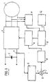
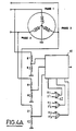
- FIG. 1 is a general block diagram of a self-piloting synchronous motor 1 which is supplied from a DC voltage source 2, for example a motor vehicle battery, via an inverter 3.
- the motor 1 comprises a permanent magnet rotor and a three-phase stator supplied by the inverter 3.
- the operation of this motor is regulated and for this purpose it comprises a current detector 4 associated with a current measurement device 5; the signal supplied by the circuit 5 is sent to a comparator 6 which also receives at 7 a current reference signal which is determined by the working conditions desired for the motor.
- the signal obtained is sent to a current control module 8, the output signal of which is sent to a pulse width modulator 9 which is controlled by a control module 10.
- the control module 10 receives in particular signals representative of zero crossings phase shifted by thirty degrees; these signals are produced by a module 11 which is the subject of the present invention and which is connected in particular to the terminals of the phase windings of the stator.
- the modulator 9 generates the control signals of the semiconductor elements of the inverter 3 from a sawtooth modulation signal at fixed frequency, the width being a function of the setpoint signal supplied by the module 8.
- a module 12 prepares special signals for starting the engine which are sent to the control module 10.
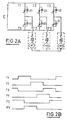
- FIG. 2A schematically represents the inverter 3 which supplies the three phase windings e1, e2 and e3 of the stator in a bidirectional manner.
- the inverter has six semiconductor elements with controlled conduction and extinction T1, T2, T3, T′1, T′2 and T′3 on each of which is connected in parallel a freewheeling diode 20 whose direction of direct conduction is opposite to the direction of direct conduction of the controlled semiconductor element.
- These controlled semiconductor elements can for example be bipolar transistors or MOS type transistors.
- the widths of the control periods of each of the semiconductors controlled each correspond to 120 electrical degrees and it can be seen that the period during which the electromotive force induced in a phase must be monitored is a period extending over sixty electrical degrees separating the control period of a semiconductor, T1 for example and the control period of the associated semiconductor, T′1.
- the offset between a zero crossing of the induced electromotive force and the next control of a semiconductor element of the inverter is thirty electrical degrees. It is therefore necessary to make a phase shift of this value in order to obtain, from the signal representative of the zero crossing of the electromotive force, the control signals of the semiconductor elements.
- the periods of 60 electrical degrees during which it is necessary to detect the zero crossing of the electromotive force of a winding correspond to periods when none of the semiconductor elements associated with the phase considered is controlled.
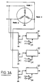
- FIG. 3A represents a circuit which makes it possible to eliminate for each of the windings the periods during which said winding is supplied in one direction or another.
- the voltage across each winding is taken and sent to a divider bridge made up of two resistors R1 and R2 for each winding.
- the voltage taken from the divider bridge is sent to an analog switch 31, respectively 32 or 33, each switch is controlled by a NOR logic gate having two inputs each receiving the control voltage of a controlled semiconductor T1, respectively T2 or T3, and of the associated controlled semiconductor T′1, respectively T′2 or T′3.
- the circuit of FIG. 3A therefore masks the periods during which the winding whose voltage is monitored is supplied by the inverter.
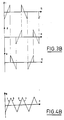
- FIG. 4A represents an alternative embodiment in which a global signal S is produced, the frequency of which is three times the frequency of the signal for the passage to zero of the electromotive force induced by a winding. Indeed, as can be seen in FIG. 3B, if we add the three signals of each of the phases, we obtain the continuous signal S of FIG. 4B.
- an analog switch 41 which has three inputs each controlled separately and a single output. Each input is controlled by a NOR logic gate 42 analogous to the gates 34 of FIG. 3A.
- FIG. 5 is a curve showing the detail of the voltage across a non-powered winding, the curve below representing the control signal of the transistors. It can be seen that the voltage across the winding is disturbed by the voltages induced, at the modulation frequency, by the switching of the semiconductors relating to the other phases. It is therefore necessary to provide a filtering of the signal observed at the terminals of each winding. This filtering consists in taking from this signal only the portions corresponding to the conductions of the transistors. In addition to avoid capturing the oscillations that appear on these portions at each switching, this sampling is carried out through a window of adequate width.
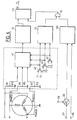
- FIG 6 is a block diagram of the module 11 of Figure 1 which provides a signal representative of the zero crossing of the electromotive force induced in each of the windings when the other two are powered. This figure shows the analog switch with three inputs 41 and the NOR logic gates 42.
- the global signal S supplied by the analog switch 41 is sent to an operational amplifier 51 which is mounted as a comparator with respect to ground; it makes it possible to detect the positive or negative value of the signal S and thus to supply a logic level at its output which is sent to a flip-flop of the D 52 type which constitutes a memory element and is driven by sampling pulses.
- the output signals of the NOR logic circuits 42 are also sent on a circuit 53 which makes it possible to mask the moments of phase permutation of the stator.
- the output of this circuit 53 is sent to an AND logic gate 54, the other input of which receives sampling pulses supplied by a circuit 55 which compares, on the one hand the sawtooth modulation signal which is applied at 56 and, on the other hand, the control signal 57 produced by the circuit 8 of FIG. 1.
- This circuit 55 is also controlled by the control signal produced by the circuit 8 of FIG. 1.
- control signal applied at 57 is added with a continuous component applied at 58 thanks to an adder 59.
- FIG. 7 respectively represents the curves of the global signal S, the sampling pulses and the signal supplied by the D type flip-flop 52 which is controlled by the sampling pulses supplied via the logic gate 54.
- the signal obtained is a rectangular signal whose each change of state corresponds to the passage through zero of the electromotive force induced in each of the windings; when this signal is at the high level, the electromotive force observed is positive and when the signal is at the low level, this electromotive force is negative.
- Each slot corresponds to a width of 60 electrical degrees.
- FIGS. 8 and 9 illustrate the embodiment of the phase shift of 30 electrical degrees, which uses two counters, one receiving the direct output signal from the flip-flop 52 and the other the inverse signal from the latter.
- the levels of the counters have been shown in an analog manner for reasons of clarification.
- the content of the first counter divided by two is compared with the content of the second counter and vice versa.
- the various curves successively represent the direct output signal S of flip-flop 52, the counting state of the first counter, this counting state divided by two, the counting state of the second counter, this counting state divided by two, the pulses corresponding to an equality for one of these count value pairs and finally the output signal which is phase shifted by half the width of the pulses of the overall signal, that is to say 30 degrees.
- the counting level of the first counter arrives at the counting level of the second counter divided by two; this results in a pulse 11 which corresponds to the rising edge of the phase shifted signal.
- the counting level of the second counter reaches the level of half the counting of the first counter and this results in the formation of a pulse 12 which corresponds to the falling edge of the phase shifted signal.
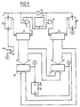
- Figure 9 is the block diagram of a device providing such a phase shift.
- a clock 70 of fixed frequency supplies clock pulses to two counters 71 and 72.
- the transmission of these clock signals to the counter 71 is controlled by the output signal S of the flip-flop 52 via a gate AND 73; with regard to the counter 72, the sending of the clock pulses is controlled by a signal opposite to the output signal of the flip-flop 52, the inversion being carried out by means of an inverter 74.
- the control of the transmission of the clock pulses are carried out via an AND circuit 75.
- the output word from each of the counters 71 and 72 which corresponds to the counting level is sent to a comparator 76, respectively 77.
- Each of these comparators also receives the value half of the output word from the other counter; that is to say that the comparator 76 compares the output word of counter 71 with the output half word of counter 72 and comparator 77 compares the output word of second counter 72 with the output half word of first counter 71.
- the signals C and D obtained at the output of the two comparators 76 and 77 control in opposite manner a flip-flop 78 whose output Q provides the signal phase shifted at 30 degrees.
- each counter a reset device constituted by a flip-flop 79, respectively 80, which is controlled by the output signal from the comparators 77 respectively 76.
- the output signal from the comparator 77 is sent to the flip-flop 79 by the through an OR gate 81 which receives an external reset signal at its other input.
- the invention makes it possible to perform efficient filtering of the parasitic signals of the electromotive force induced from each winding by means of the sampling process; this process has a high reliability and it does not introduce phase shift as would a conventional filter circuit.
- the realization of the phase shift of 30 degrees necessary to obtain the control signals of the semiconductor elements of the inverter is also obtained in a reliable and inexpensive manner thanks to the use of counters.
- the recommended solution minimizes phase difference errors during periods of motor acceleration.
- the frequency of the clock 70 is chosen so as to obtain a number of logical increments, at the level of the counters, which is sufficient for the maximum speed of the machine. So you can choose a frequency of 15 kHz; indeed, for a speed of 1000 rpm, 60 electrical degrees then correspond to 2.5 ms, which gives approximately 40 logical increments for 60 degrees.
- the logical value "1" is imposed on the first counter and the value "0" on the second.
- the reset carried out by the first comparator 76 is inhibited by using the signal C and the signal D is used to inhibit the reset made by the comparator 77.
Landscapes
- Engineering & Computer Science (AREA)
- Power Engineering (AREA)
- Control Of Motors That Do Not Use Commutators (AREA)
Claims (13)
- Verfahren zur Steuerung eines selbstgeführten dreiphasigen Synchronmotors (1) mit einem Permanentmagnetrotor und gespeist über eine Gleichspannungsquelle (2) mit bidirektionaler Speisung der Statorwicklungen (e1, e2, e3) über einen Wechselrichter (3) mit gesteuerten Halbleiterelementen (T1, T′1, T2, T′2, T3, T′3), deren Leiten und Sperren durch Impulsbreitenmodulation von Impulsen fester Frequenz gesteuert wird, wobei wenigstens eine der Wicklungen des Stators nicht gespeist wird, während die beiden anderen gespeist werden, bei welchem die Feststellung der Position des Rotors im Hinblick auf die Erzeugung der Steuersignale für den Wechselrichter (3) durch Feststellung des Nulldurchgangs der in der nicht gespeisten Wicklung induzierten elektromotorischen Kraft gewonnen wird, wobei die Steuersignale für den Wechselrichter in Bezug auf den Zeitpunkt des Nulldurchgangs phasenverschoben sind, dadurch gekennzeichnet, daß das an den Klemmen einer jeden Wicklung (e1, e2, e3) abgenommene Signal im Hinblick auf die Feststellung des Nulldurchgangs der elektromotorischen Kraft, die es darstellt, mit Synchronisation mit der Modulationsfrequenz des Wechselrichters abgefragt wird.
- Steuerverfahren nach Anspruch 1, dadurch gekennzeichnet, daß für die Feststellung des Nulldurchgangs der elektromotorischen Kraft eine Maskierung der Perioden, während welcher die der Wicklung zugeordneten Halbleiter in Leitung sind, vorgenommen wird.
- Steuerverfahren nach Anspruch 1 oder 2, dadurch gekennzeichnet, daß eine Maskierung der Phasenvertauschungszeitpunkte vorgenommen wird.
- Steuerverfahren nach irgendeinem der Ansprüche 1 bis 3, dadurch gekennzeichnet, daß das der Beobachtung der elektromotorischen Kräfte dienende Abfragesignal durch Vergleichen des Sägezahnmodulationssignals mit dem vom Stromsteuermodul abgegebenen Steuersignal gewonnen wird, wobei eine Gleichspannungskomponente dem Steuersignal hinzugefügt wird.
- Steuerverfahren nach irgendeinem der Ansprüche 1 bis 4, dadurch gekennzeichnet, daß die Phasenverschiebung des Signals für den Nulldurchgang der elektromotorischen Kraft durch Zählung von Taktimpulsen fester Frequenz in einem System von zwei Zählern gewonnen wird.
- Steuerverfahren nach Anspruch 5, dadurch gekennzeichnet, daß eine erste Zählung, welche durch ein den Nulldurchgang der elektromotorischen Kraft darstellendes Signal gesteuert wird, und eine zweite Zählung, welche durch das zu diesem Signal inverse Signal gesteuert wird, durchgeführt wird, wobei der Wert einer der Zählungen mit dem Halbwert der anderen Zählung verglichen wird und umgekehrt.
- Steuerverfahren nach Anspruch 2, dadurch gekennzeichnet, daß ein einziges Signal erzeugt wird, welches der Folge der an den einzelnen Spulen abgenommenen Signale nach Maskierung der Perioden der Speisung der betrachteten Spule entspricht, erzeugt wird.
- Vorrichtung zum Nachweis des Nulldurchgangs der in den einzelnen Spulen eines selbstgeführten dreiphasigen Synchronmotors induzierten elektromotorischen Kraft, dadurch gekennzeichnet, daß sie ein Kippglied (52) aufweist, welches auf einem seiner Eingänge das an den Wicklungsklemmen abgenommene Signal erhält und durch Abfrageimpulse gesteuert wird, welche anhand des Sägezahnmodulationssignals des die Wicklungen des Stators des Motors speisenden Wechselrichters gewonnen sind.
- Vorrichtung nach Anspruch 8, dadurch gekennzeichnet, daß sie für jede Wicklung einen Analogschalter (31, 32, 33) aufweist, welcher die an einer Wicklung abgenommene Spannung erhält und durch ein NICHT-ODER-Glied (34) gesteuert wird, welches an seinen beiden Eingängen die Steuersignale für die der betrachteten Phase zugeordneten gesteuerten Halbleiter erhält.
- Vorrichtung nach Anspruch 8, dadurch gekennzeichnet, daß sie einen Analogschalter (41) mit drei Eingängen aufweist, welche die an den drei Wicklungen abgenommenen Spannungen erhalten und durch drei NICHT-ODER-Glieder (42) gesteuert werden.
- Vorrichtung nach Anspruch 10, dadurch gekennzeichnet, daß sie eine Schaltung (53) zur Maskierung der Phasenvertauschungen aufweist, die durch die NICHT-ODER-Glieder (42) gesteuert wird.
- Vorrichtung nach irgendeinem der Ansprüche 8 bis 11, dadurch gekennzeichnet, daß sie zwei Zähler (71, 72), von welchen der eine das direkte Signal des Nulldurchgangs der elektromotorischen Kraft und der andere das inverse Signal erhält, zwei Komparatoren (76, 77), welche jeweils das Zählsignal des einen Zählers und das Zählsignal des anderen Zähler geteilt durch 2 erhalten, und ein Kippglied (78), welches durch die Ausgangssignale der beiden Komparatoren gesteuert wird, aufweist.
- Vorrichtung nach Anspruch 12, dadurch gekennzeichnet, daß das Ausgangssignal jedes Komparators (76, 77) die Nullung des Zählers (72, 71), von dem er die Hälfte des Zählsignals erhält, steuert.
Applications Claiming Priority (2)
| Application Number | Priority Date | Filing Date | Title |
|---|---|---|---|
| FR9003825 | 1990-03-26 | ||
| FR9003825A FR2660126B1 (fr) | 1990-03-26 | 1990-03-26 | Procede de commande d'un moteur synchrone autopilote et dispositif pour sa mise en óoeuvre. |
Publications (2)
| Publication Number | Publication Date |
|---|---|
| EP0449687A1 EP0449687A1 (de) | 1991-10-02 |
| EP0449687B1 true EP0449687B1 (de) | 1994-06-01 |
Family
ID=9395107
Family Applications (1)
| Application Number | Title | Priority Date | Filing Date |
|---|---|---|---|
| EP19910400635 Expired - Lifetime EP0449687B1 (de) | 1990-03-26 | 1991-03-07 | Regelprozess eines selbstgeführten Synchronmotors und Vorrichtung zu seiner Verwendung |
Country Status (3)
| Country | Link |
|---|---|
| EP (1) | EP0449687B1 (de) |
| DE (1) | DE69102180T2 (de) |
| FR (1) | FR2660126B1 (de) |
Cited By (2)
| Publication number | Priority date | Publication date | Assignee | Title |
|---|---|---|---|---|
| EP0544628A2 (de) * | 1991-10-31 | 1993-06-02 | STMicroelectronics S.r.l. | Startprozedur für einen bürsten- und sensorlosen Motor |
| EP1020019B1 (de) * | 1997-10-06 | 2002-05-29 | Micro-Beam S.A.R.L. | Gerät und verfahren zur steuerung eines synchronmotors mit permanentmagnet |
Families Citing this family (8)
| Publication number | Priority date | Publication date | Assignee | Title |
|---|---|---|---|---|
| FR2785738B1 (fr) * | 1998-11-06 | 2001-05-04 | Valeo Electronique | Commande de moteur electrique de groupe moto-ventilateur de vehicule automobile |
| US7288910B2 (en) | 2003-12-01 | 2007-10-30 | Pratt & Whitney Canada Corp. | Sensorless control in a permanent magnet machine |
| BG66312B1 (bg) * | 2007-11-15 | 2013-03-29 | БлаговестNachev Blagovest НАЧЕВ | Метод за управление на синхронен електродвигател |
| US8076882B2 (en) | 2007-12-26 | 2011-12-13 | Pratt & Whitney Canada Corp. | Motor drive architecture with active snubber |
| CN102281029B (zh) * | 2011-08-31 | 2013-10-30 | 南京信息职业技术学院 | 一种无轴承同步磁阻电机悬浮系统构造方法 |
| CN102545767B (zh) * | 2012-01-16 | 2014-12-10 | 南京信息职业技术学院 | 无轴承同步磁阻电机解耦控制系统及其构造方法 |
| CA2921552C (en) * | 2013-08-19 | 2018-07-17 | Siemens Aktiengesellschaft | Control method for self-commutated converter for controlling power exchange |
| CN105914708B (zh) * | 2016-06-29 | 2019-08-27 | 广东美的环境电器制造有限公司 | 用于风扇的触网停机保护电路和具有其的风扇 |
Family Cites Families (5)
| Publication number | Priority date | Publication date | Assignee | Title |
|---|---|---|---|---|
| JPS61121793A (ja) * | 1984-11-15 | 1986-06-09 | Matsushita Electric Ind Co Ltd | ブラシレス直流モ−タ |
| DE3602227A1 (de) * | 1986-01-25 | 1987-07-30 | Philips Patentverwaltung | Kommutierungsschaltung fuer einen kollektorlosen gleichstrommotor |
| JP2502620B2 (ja) * | 1987-09-04 | 1996-05-29 | 松下電器産業株式会社 | ブラシレスモ―タの駆動装置 |
| JP2659737B2 (ja) * | 1988-01-28 | 1997-09-30 | 株式会社東芝 | ブラシレスモータの駆動装置 |
| JP2667216B2 (ja) * | 1988-08-10 | 1997-10-27 | ソニー株式会社 | ブラシレスモータの駆動回路 |
-
1990
- 1990-03-26 FR FR9003825A patent/FR2660126B1/fr not_active Expired - Fee Related
-
1991
- 1991-03-07 DE DE1991602180 patent/DE69102180T2/de not_active Expired - Fee Related
- 1991-03-07 EP EP19910400635 patent/EP0449687B1/de not_active Expired - Lifetime
Cited By (5)
| Publication number | Priority date | Publication date | Assignee | Title |
|---|---|---|---|---|
| EP0544628A2 (de) * | 1991-10-31 | 1993-06-02 | STMicroelectronics S.r.l. | Startprozedur für einen bürsten- und sensorlosen Motor |
| EP0544628A3 (en) * | 1991-10-31 | 1993-08-04 | Sgs-Thomson Microelectronics S.P.A. | Start-up procedure for a brushless, sensorless motor |
| US5343127A (en) * | 1991-10-31 | 1994-08-30 | Sgs-Thomson Microelectronics, S.R.L. | Start-up procedure for a brushless, sensorless motor |
| US5397972A (en) * | 1991-10-31 | 1995-03-14 | Sgs-Thomson Microelectronics, S.R.L. | Start-up procedure for a brushless, sensorless motor |
| EP1020019B1 (de) * | 1997-10-06 | 2002-05-29 | Micro-Beam S.A.R.L. | Gerät und verfahren zur steuerung eines synchronmotors mit permanentmagnet |
Also Published As
| Publication number | Publication date |
|---|---|
| DE69102180T2 (de) | 1995-03-02 |
| EP0449687A1 (de) | 1991-10-02 |
| FR2660126A1 (fr) | 1991-09-27 |
| DE69102180D1 (de) | 1994-07-07 |
| FR2660126B1 (fr) | 1995-06-16 |
Similar Documents
| Publication | Publication Date | Title |
|---|---|---|
| FR2747521A1 (fr) | Commande d'un moteur sans collecteur | |
| EP1974455B1 (de) | Vorrichtung zur steuerung einer polyphasen-rotationsmaschine | |
| EP0449687B1 (de) | Regelprozess eines selbstgeführten Synchronmotors und Vorrichtung zu seiner Verwendung | |
| FR2811824A1 (fr) | Moteur electrique a deux modes de communication d'alimentation | |
| FR2470477A1 (fr) | Moteur a courant continu sans balai | |
| FR2458940A1 (fr) | Dispositif d'attaque de moteur a courant continu sans balai | |
| FR2785106A1 (fr) | Procede et dispositif pour detecter la vitesse de rotation d'un moteur a courant continu commande par un signal a modulation de largeur d'impulsions | |
| FR2521799A1 (fr) | Dispositif de commande d'un moteur electrique pas a pas | |
| EP3014758B1 (de) | Motorsteuerungsvorrichtung | |
| CH670341A5 (de) | ||
| FR2753318A1 (fr) | Dispositif de mesure de courants dans un onduleur | |
| WO2006027480A1 (fr) | Module de commande et de puissance pour une machine electrique tournante | |
| EP0936728B1 (de) | Regelung eines Unsymmetrien enthaltenden bürstenlosen Motors | |
| EP3213404B1 (de) | Vorrichtung zur steuerung einer mehrphasigen synchronen elektrischen drehmaschine und zugehörige umkehrbare elektrische maschine für ein kraftfahrzeug | |
| FR2502861A1 (fr) | Moteur a courant continu | |
| FR2478400A1 (fr) | Dispositif de commande d'un moteur electrique | |
| EP2605400B1 (de) | Steuerverfahren eines Wechselrichters für die Stromversorgung eines Motors, und entsprechendes Steuermodul | |
| EP0904632B1 (de) | Regelvorrichtung eines elektrischen motors für eine servolenkung | |
| FR2639489A1 (fr) | Dispositif interrupteur de puissance, notamment pour convertisseur de frequence | |
| EP0241326B1 (de) | Verfahren zur Regelung eines Pulsbreitenmodulierten Wechselrichters mit n-phasigem Motor und Gerät zur Realisierung des Verfahrens | |
| FR2701339A1 (fr) | Dispositif d'alimentation électrique délivrant une tension aux polarités alternées de manière cyclique. | |
| FR2562737A1 (fr) | Procede et circuit de commande d'un moteur pas a pas alimente par une tension continue | |
| CA2193730A1 (fr) | Procede de commande d'un gradateur de tension pour l'alimentation d'un moteur a induction | |
| FR3083402A1 (fr) | Moteur electrique a courant continu sans balai et procede de commande associe | |
| EP0519805A1 (de) | Regler mit Messung der Spannung zwischen den Phasen in einem Drehstromgenerator |
Legal Events
| Date | Code | Title | Description |
|---|---|---|---|
| PUAI | Public reference made under article 153(3) epc to a published international application that has entered the european phase |
Free format text: ORIGINAL CODE: 0009012 |
|
| 17P | Request for examination filed |
Effective date: 19910703 |
|
| AK | Designated contracting states |
Kind code of ref document: A1 Designated state(s): DE GB IT |
|
| 17Q | First examination report despatched |
Effective date: 19930921 |
|
| GRAA | (expected) grant |
Free format text: ORIGINAL CODE: 0009210 |
|
| ITF | It: translation for a ep patent filed |
Owner name: BARZANO' E ZANARDO MILANO S.P.A. |
|
| AK | Designated contracting states |
Kind code of ref document: B1 Designated state(s): DE GB IT |
|
| GBT | Gb: translation of ep patent filed (gb section 77(6)(a)/1977) |
Effective date: 19940607 |
|
| REF | Corresponds to: |
Ref document number: 69102180 Country of ref document: DE Date of ref document: 19940707 |
|
| PLBE | No opposition filed within time limit |
Free format text: ORIGINAL CODE: 0009261 |
|
| STAA | Information on the status of an ep patent application or granted ep patent |
Free format text: STATUS: NO OPPOSITION FILED WITHIN TIME LIMIT |
|
| 26N | No opposition filed | ||
| REG | Reference to a national code |
Ref country code: GB Ref legal event code: IF02 |
|
| PGFP | Annual fee paid to national office [announced via postgrant information from national office to epo] |
Ref country code: GB Payment date: 20050225 Year of fee payment: 15 |
|
| PGFP | Annual fee paid to national office [announced via postgrant information from national office to epo] |
Ref country code: DE Payment date: 20060227 Year of fee payment: 16 |
|
| PG25 | Lapsed in a contracting state [announced via postgrant information from national office to epo] |
Ref country code: GB Free format text: LAPSE BECAUSE OF NON-PAYMENT OF DUE FEES Effective date: 20060307 |
|
| PGFP | Annual fee paid to national office [announced via postgrant information from national office to epo] |
Ref country code: IT Payment date: 20060331 Year of fee payment: 16 |
|
| GBPC | Gb: european patent ceased through non-payment of renewal fee |
Effective date: 20060307 |
|
| PG25 | Lapsed in a contracting state [announced via postgrant information from national office to epo] |
Ref country code: DE Free format text: LAPSE BECAUSE OF NON-PAYMENT OF DUE FEES Effective date: 20071002 |
|
| PG25 | Lapsed in a contracting state [announced via postgrant information from national office to epo] |
Ref country code: IT Free format text: LAPSE BECAUSE OF NON-PAYMENT OF DUE FEES Effective date: 20070307 |