EP0449286B1 - Pile driver - Google Patents
Pile driver Download PDFInfo
- Publication number
- EP0449286B1 EP0449286B1 EP91104984A EP91104984A EP0449286B1 EP 0449286 B1 EP0449286 B1 EP 0449286B1 EP 91104984 A EP91104984 A EP 91104984A EP 91104984 A EP91104984 A EP 91104984A EP 0449286 B1 EP0449286 B1 EP 0449286B1
- Authority
- EP
- European Patent Office
- Prior art keywords
- vibration cylinder
- piston
- pile
- valve
- electro
- Prior art date
- Legal status (The legal status is an assumption and is not a legal conclusion. Google has not performed a legal analysis and makes no representation as to the accuracy of the status listed.)
- Expired - Lifetime
Links
- 238000006073 displacement reaction Methods 0.000 claims description 13
- 238000010276 construction Methods 0.000 claims description 7
- 238000006243 chemical reaction Methods 0.000 description 2
- 238000005553 drilling Methods 0.000 description 2
- 230000005484 gravity Effects 0.000 description 2
- 239000003921 oil Substances 0.000 description 2
- 230000001133 acceleration Effects 0.000 description 1
- 230000002238 attenuated effect Effects 0.000 description 1
- 230000005540 biological transmission Effects 0.000 description 1
- 230000000295 complement effect Effects 0.000 description 1
- 230000002079 cooperative effect Effects 0.000 description 1
- 230000000875 corresponding effect Effects 0.000 description 1
- 230000001419 dependent effect Effects 0.000 description 1
- 230000000694 effects Effects 0.000 description 1
- 238000011067 equilibration Methods 0.000 description 1
- 239000010720 hydraulic oil Substances 0.000 description 1
Images




Classifications
-
- E—FIXED CONSTRUCTIONS
- E02—HYDRAULIC ENGINEERING; FOUNDATIONS; SOIL SHIFTING
- E02D—FOUNDATIONS; EXCAVATIONS; EMBANKMENTS; UNDERGROUND OR UNDERWATER STRUCTURES
- E02D7/00—Methods or apparatus for placing sheet pile bulkheads, piles, mouldpipes, or other moulds
- E02D7/18—Placing by vibrating
-
- B—PERFORMING OPERATIONS; TRANSPORTING
- B06—GENERATING OR TRANSMITTING MECHANICAL VIBRATIONS IN GENERAL
- B06B—METHODS OR APPARATUS FOR GENERATING OR TRANSMITTING MECHANICAL VIBRATIONS OF INFRASONIC, SONIC, OR ULTRASONIC FREQUENCY, e.g. FOR PERFORMING MECHANICAL WORK IN GENERAL
- B06B1/00—Methods or apparatus for generating mechanical vibrations of infrasonic, sonic, or ultrasonic frequency
- B06B1/18—Methods or apparatus for generating mechanical vibrations of infrasonic, sonic, or ultrasonic frequency wherein the vibrator is actuated by pressure fluid
- B06B1/183—Methods or apparatus for generating mechanical vibrations of infrasonic, sonic, or ultrasonic frequency wherein the vibrator is actuated by pressure fluid operating with reciprocating masses
Definitions
- the signal (voltage) from the signal generator 8 and said feedback signal are compared, and the difference is transmitted as an input electric current to the electro-hydraulic servo-valve 5, which moves the piston 41 in the direction to lessen the difference.
- the piston 41 of the vibration cylinder 4 is made to vibrate profiling the wave form of the signal from the signal generator 8.
- the signal desired to be generated from the generator 8, that is, the operation condition of the pile driver can be easily set by turning the adjusting dial (not shown) attached thereto.
- 3 is shown a two-stage, most typical electro-hydraulic servo-valve to facilitate comprehension of the work principle; if an actuator of greater capacity is to be controlled, a three-stage electro-hydraulic servo- valve can be adopted.
- a three-stage electro-hydraulic servo-valve the work principle that the output flow is controlled through displacement of the spool which is made to be proportional to the input electric current, is the same with the typical servo-valve described above.
Landscapes
- Engineering & Computer Science (AREA)
- Life Sciences & Earth Sciences (AREA)
- General Life Sciences & Earth Sciences (AREA)
- Mining & Mineral Resources (AREA)
- Paleontology (AREA)
- Civil Engineering (AREA)
- General Engineering & Computer Science (AREA)
- Structural Engineering (AREA)
- Mechanical Engineering (AREA)
- Placing Or Removing Of Piles Or Sheet Piles, Or Accessories Thereof (AREA)
- Operation Control Of Excavators (AREA)
Description
- This invention relates to pile driver comprising a pile driving device construction equipment provided at the end of a work-arm that serves as a base machine for operation against the ground.
- A conventional pile driver of this type is known which comprises, as a base machine, a construction equipment such as an excavator having a work-arm for drilling, crushing and other works against the ground, and a rotating eccentric weight type pile driving device attached at the end of the arm.
- This type of pile driver drives a pile into the ground under the force which is a superposition of the centrifugal force due to rotation of the eccentric weights, a portion of the gravity force acting on the base machine, and the hydraulic force from the hydraulic cylinder mounted on the base machine.
- In this type of pile driver, it is obvious that, since the driving force is generated by rotation of eccentric weights, to get a greater driving force, it is necessary to increase either the mass of the eccentric-weights or the revolution rate or the eccentric throw, which however, means necessarily greater loads on the axles supporting the eccentric weights, on the bearings supporting the axles rotatability, and on the frame holding the bearings and the power transmission mechanism.
- To avoid this inconvenience, a new type pile driver has been proposed by the same inventors as of the present invention, disclosed in the EP-A-0 276 845 cf. the pre-characterising portion of claim 1. The main feature of this pile driver is that the alternating force from the vibration cylinder is not attenuated when a pull-up or pull-down force is exerted by any other construction machine such as a crane truck, a leader etc. To achieve this object, the pile driver comprises a self-equilibration cylinder arranged vertically in series with the vibration cylinder.
- The object of the invention is to provide a high-frequency type pile driver that not only is exempt from the drawbacks of the prior art which causes vibration public hazard but also can exert effectively large driving force or pull out force when attached to a work-arm of a construction equipment.
- The invention solves the object by a pile driver as defined in claim 1; advantageous features are introduced in the dependent claims. It is described in the following description by way of example and with reference to the drawings, which show in
- Fig. 1
- a side sectional view of an embodiment of the invention;
- Fig. 2
- a side sectional view showing a servo control system that controls the vibration cylinder;
- Fig. 3
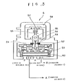
- a side sectional view showing a typical example of an electro-hydraulic servo-valve;
- Fig. 4
- a side elevational view of an embodiment of the invention in a pile driving operation; and
- Fig. 5
- a side sectional view similar to Fig. 1, showing another embodiment of the invention.
- An embodiment of the invention will be described with reference to Fig. 1 to Fig. 4. In Fig. 1 numeral 1 designates an attachment frame of arch shape, which is fixed to the forward end of a work-
arm 12 of the base machine 11 (Fig. 4) by means of a fixing axle 1A. As a base machine, a rather heavy construction equipment such as an excavator or a road ripper having a work-arm 12 to carry out drilling, pounding and other operation is suited. - Inside the arch of the attachment frame 1 is fixed a
frame 3A through abuffer rubber 3, and avibration cylinder 4 is provided in theframe 3A with thepiston 41 directed downward. At the lower end of saidpiston 41 is fixed achucking means 6 for gripping a pile K to be driven. To thepiston 41 is fixed acounter weight 2 at the end of thevibration cylinder 4 opposite with respect to thechucking means 6, that is at the base end of the cylinder, as shown in Fig. 2. Thechucking means 6 is provided in such a manner that the pile K is gripped to be in alignment with the axis of thevibration cylinder 4. - To the
vibration cylinder 4 is attached an electro-hydraulic servo-valve 5 for actuation and control thereof; on the side surface is attached adisplacement sensor 7 to detect the displacement of thepiston 41. - A
signal generator 8 is provided to generate control signals to actuate and control said electro-hydraulic servo-valve 5. The signal generator can generate, as shown in Fig. 2, control signals of various wave forms ; rectangular, sinusoidal, and others. The signals generated by thesignal generator 8 are transmitted to the electro-hydraulic servo-valve 5 via a servo-amplifier 10. Also, afeedback signal circuit 9 connecting between thepiston displacement sensor 7 and the servo-amplifier 10 is provided to form a servo control system that controls thevibration cylinder 4 through the electro-hydraulic servo-valve 5. - The outline of action of said servo control system is as follows; the actuation signal from the
signal generator 8 moves aspool 52 in the electro-hydraulic servo-valve 5 in accordance with polarity and magnitude of electric current of the signal, which, in turn, shifts thepiston 41 of thevibration cylinder 4 upward or downward(Action of the electro-hydraulic servo-balve 5 Will be described later with reference to Fig. 3). The direction and magnitude of this displacement of thepiston 41 is detected by thepiston displacement sensor 7 and a feedback signal (voltage) proportional to sensed quantity is transmitted to the servo-amplifier 10. In the servo-amplifier 10, the signal (voltage) from thesignal generator 8 and said feedback signal are compared, and the difference is transmitted as an input electric current to the electro-hydraulic servo-valve 5, which moves thepiston 41 in the direction to lessen the difference. Thus, thepiston 41 of thevibration cylinder 4 is made to vibrate profiling the wave form of the signal from thesignal generator 8. The signal desired to be generated from thegenerator 8, that is, the operation condition of the pile driver can be easily set by turning the adjusting dial (not shown) attached thereto. - Since, to the vibration cylinder is fixed the
counter weight 2, a reaction force that is proportional to acceleration of thecylinder 41 is generated by the vibration of saidcylinder 41, which is transmitted to the pile K through the chucking means 6 fixed to the lower end of thepiston 41. The force transmitted possesses the same frequency as thepiston 41, is proportional to the mass of thecounter weight 2, and is directed to be in alignment with the axis of the vibration cylinder that is, the axis of the pile K. With its attached servo-valve 5 andpiston displacement sensor 7, thevibration cylinder 4, thecounter weight 2 and thechucking means 6 is supported by asupport frame 3A connected to the attachment frame 1 through abuffer rubber 3 whereby the chucking means 6 is directly connected to saidsupport frame 3A. - Fig. 5 shows another embodiment of the invention, which is different from the embodiment described hereinabove only in that the direction of the
vibration cylinder 4 is reversed in so far as thecounter weight 2 is fixed to the end of thepiston 41 while thechucking means 6 is fixed to the base of thevibration cylinder 4. With this modified embodiment, the operation is quite the same with the above embodiment. - Here, with reference to Fig. 3, the construction and action of the electro-hydraulic servo-
valve 5 will be described. The electro-hydraulic servo-valve comprises, roughly speaking, a four-port spool valve part, a torque motor part, and a primary hydraulic amplifier part. The four-port spool valve part consists of asleeve 51 and aspool 52 that engages slidably inside saidsleeve 51. Thespool 52 possesses land portions on the both ends and effects communication or disconnection among the four ports; the entrance port P for hydraulic oil, the return port R to a tank, and a pair of passages A and B which lead to an actuator or thevibration cylinder 4 in this case. The member that is shown as a tube below thespool 52 is a filter which has fixedorifices 60 at the both ends. - The torque motor part consists of a
permanent magnet 58, anelectromagnetic coil 56, and anarmature 57. Thearmature 57 is mounted to be rotatable about the central axle on which is exerted a torque due to atorsion spring 55, and aflapper 54 is fixed on the opposite side of saidarmature 57 with respect to said central axle. Afeedback spring 59 is attached at the end of said flapper and the other end thereof is engaged with the center of thespool 52 through an appropriate ball. On both sides of the flapper are provided a pair ofnozzles 53 facing each other. which are severally in communication with the end faces of the spool 52 (let the pressures on them be P₁ and P₂ ), and a flow passage for a part of oil entering from the port P is formed by way of thefixed orifices 60 on the both sides. Theflapper 54, the pair ofnozzles 53 and the fixed orifices described above constitue the primary hydraulic amplifier. - When the input signal current to the electro-hydraulic servo-
valve 5 is zero, thearmature 57, hence theflapper 54, is at the central position as shown, and the back pressures P₁ and P₂ behind thenozzles 53 are equal, which keeps the spool at the central position shown in Fig. 3. Now let a small electric current (input signal) of either polarity (plus or minus) increase through theelectromagnetic coil 56 to change the magnetic field of thepermanent magnet 58, and let thereby thearmature 57 be turned to one direction, to the left for example, then the flapper will move to the right and will cause a higher back pressure P₂ on the right nozzle than the pressure P₁ on the left nozzle (P₂ > P₁), which moves thespool 52 to the left. The displacement of thespool 52 continues until the back pressures on the nozzles again come to an equilibrium which is effected by pulling back theflapper 54 by thefeedback spring 59. The commumication relationship among the four ports of the four-port spool valve part when thespool 52 stops is such that oil flows in the path: the entrance port P → A → thevibration cylinder 4 → B → the return port R. If the port A is in communication with the head side of thevibration cylinder 4, then thepiston 41 extends out in responce to the above said input signal. If the polarity of the input signal is reversed, the action is similar but the spool moves to the right by a quantity. Thus, in an electro-hydraulic servo-valve, the spool moves a distance in the direction corresponding to the sign (plus or minus) and in proportion to the magnitude of the input signal, which also means the output flow to be proportional to the input electric current. - In this manner, the use of the electro-hydraulic servo-
valve 5 makes it possible to operate and control a large-capacity actuator by means of small electric current of the order of milliampere. Moreover, the electro-hydraulic servo-valve permits a faithful profiling of magnitude and polarity of the input electric current of the input signal, and, the machine can follow well up to several tens of herz of frequency variation, keeping thecounter weight 2 at about the center of the vibration under the cooperative action of the servo control system consisting of thepiston displacement sensor 7, thesignal generator 8, thefeedback signal circuit 9 and the servo-amplifier 10. In Fig. 3 is shown a two-stage, most typical electro-hydraulic servo-valve to facilitate comprehension of the work principle; if an actuator of greater capacity is to be controlled, a three-stage electro-hydraulic servo- valve can be adopted. Of course, with a three-stage electro-hydraulic servo-valve, the work principle that the output flow is controlled through displacement of the spool which is made to be proportional to the input electric current, is the same with the typical servo-valve described above. - In actual pile driving operation, the
base machine 11 is set with the front wheels raised as shown in Fig. 4 so that most of the weight therof is transferred to the pile K through the attachment frame 1. To say more accurately, it is more convenient if the distance between the vertical line of the pile and thebase machine 11 is as short as possible. The force that acts on the pile K is, therefore, superposition of the reaction force from thevibration cylinder 4 described above, tile gravity force on the counter weight, and most part of the machine weight itself, On the other hand, if the base machine is sufficiently fixed, instead of making use of the machine weight as shown in Fig. 4, it is possible to complement the driving force on the pile K by forcing the end of the work-arm in the direction of the pile axis by means of a hydraulic cylinder mounted on the machine. - Also, the works-arm can be readily made use of for pulling out a pile K from the ground although this depends on the kind of the
base machine 11.
Claims (3)
- A pile driver comprising a pile driving device provided at the end of a work-arm (12) of an appropriate construction equipment that serves as a base machine (11), said pile driving device having a pile driving vibration cylinder (4) supported on an attachment frame (1) that is to be fixed to the end of said work-arm (12), further having a counter weight (2) provided at the axial end of said vibration cylinder (4) opposite the ground and a chucking means (6) for gripping a pile K to be driven at the other axial end of said vibration cylinder (4) facing the ground, and further a servo control system which consists of an electro-hydraulic servo-valve (5) that actuates and controls said vibration cylinder (4), a piston displacement sensor (7) that detects displacement of the piston (41) of said vibration cylinder (4), a signal generator (8) that generates input signals to said electro-hydraulic servo-valve (5), a feedback signal circuit (9) that transmits the detected signal from said piston displacement sensor to said electro-hydraulic servo-valve (5) and a servo-amplifier (10) that compares the signal from said signal generator (8) and the signal from said piston displacement sensor (7);
characterized in that
the assembly comprising the vibration cylinder (4), the counter weight (2), and the chucking means (6) is supported by a support frame (3A) connected to the attachment frame (1) through a buffer rubber (3), and that said chucking means (6) is directly connected to said support frame (3A). - A pile driver claimed in claim 1 characterized in that said vibration cylinder (4) is fixed to said attachment frame (1) in such a manner that the extension side of the piston (41) thereof faces the ground.
- A pile driver claimed in claim 1 characterized in that said vibration cylinder (4) is fixed to said attachment frame (1) in such a manner that the extension side of the piston (41) thereof faces the direction opposite the ground.
Applications Claiming Priority (2)
| Application Number | Priority Date | Filing Date | Title |
|---|---|---|---|
| JP82184/90 | 1990-03-29 | ||
| JP8218490 | 1990-03-29 |
Publications (2)
| Publication Number | Publication Date |
|---|---|
| EP0449286A1 EP0449286A1 (en) | 1991-10-02 |
| EP0449286B1 true EP0449286B1 (en) | 1994-12-07 |
Family
ID=13767358
Family Applications (1)
| Application Number | Title | Priority Date | Filing Date |
|---|---|---|---|
| EP91104984A Expired - Lifetime EP0449286B1 (en) | 1990-03-29 | 1991-03-28 | Pile driver |
Country Status (5)
| Country | Link |
|---|---|
| US (1) | US5168938A (en) |
| EP (1) | EP0449286B1 (en) |
| JP (1) | JP2729969B2 (en) |
| KR (1) | KR100218997B1 (en) |
| DE (1) | DE69105574T2 (en) |
Families Citing this family (20)
| Publication number | Priority date | Publication date | Assignee | Title |
|---|---|---|---|---|
| KR100440729B1 (en) * | 2001-05-16 | 2004-07-19 | 김억수 | Vibratory Hammer for Excavator |
| NZ528332A (en) * | 2003-09-22 | 2006-04-28 | Ramet Holdings Ltd | Impact driver for driving poles, piles or posts including linear induction motor |
| US7296475B2 (en) * | 2005-03-18 | 2007-11-20 | Conner Charles C | Displacement instrument for determining the modulus of a material |
| US7080958B1 (en) | 2005-04-27 | 2006-07-25 | International Construction Equipment, Inc. | Vibratory pile driver/extractor with two-stage vibration/tension load suppressor |
| US20080072656A1 (en) * | 2006-03-18 | 2008-03-27 | Conner Charles C | Displacement instrument |
| WO2008033139A1 (en) * | 2006-09-15 | 2008-03-20 | Conner Charles C | Pressure transducer for measuring hydraulic breaker displacement and determining aggregate modulus during compaction |
| EP2067533B2 (en) * | 2007-12-06 | 2016-12-07 | ABI Anlagentechnik-Baumaschinen-Industriebedarf Maschinenfabrik und Vertriebsgesellschaft mbH | Vibrator for a vibratory pile driver |
| EP2085148B1 (en) * | 2008-01-29 | 2013-09-18 | ABI Anlagentechnik-Baumaschinen-Industriebedarf Maschinenfabrik und Vertriebsgesellschaft mbH | Vibrator for a vibratory pile driver |
| DE102014003117B4 (en) * | 2014-03-11 | 2017-09-28 | Thyssenkrupp Ag | Apparatus and method for picking up pile pile and / or introducing pile pile into the soil |
| FI20140081A7 (en) | 2014-03-19 | 2015-09-20 | Movax Oy | Impact device to be connected to a working machine |
| NL2013871B1 (en) * | 2014-06-10 | 2016-05-03 | Cape Holland Holding B V | Vibrating device and method for placing a foundation element in a substrate. |
| CN105625417B (en) * | 2016-01-30 | 2017-06-23 | 周兆弟 | Piling machine variable cross-section piling control method and its system |
| DK3417951T3 (en) * | 2017-06-19 | 2022-07-04 | Eurodrill Gmbh | DEVICE AND METHOD FOR GENERATING IMPACT PULSE OR VICTIONS FOR A BUILDING MACHINE |
| BR112020020492A2 (en) * | 2018-04-24 | 2021-01-12 | Resemin S.A. | ELECTRIC HYDRAULIC JUMBO |
| CN109024544B (en) * | 2018-07-02 | 2020-09-15 | 中国铁路总公司 | Hydraulic high-frequency compaction treatment method for collapsible loess tunnel substrate |
| KR200491468Y1 (en) * | 2018-08-06 | 2020-04-13 | 춘 산 왕 | Radiate heat structure for strike in piling machine |
| US11338326B2 (en) * | 2019-04-07 | 2022-05-24 | Resonance Technology International Inc. | Single-mass, one-dimensional resonant driver |
| PT4214366T (en) * | 2020-09-17 | 2025-09-30 | Cape Holland Holding B V | Clamping device for a vibrating device for inserting a foundation element, vibrating device provided therewith and method there for |
| CN112761151B (en) * | 2021-01-23 | 2025-02-14 | 山东临工工程机械有限公司 | Impact pile driving mechanism and pile driver |
| CN112761152B (en) * | 2021-01-23 | 2024-11-29 | 山东临工工程机械有限公司 | Pile driving mechanism and pile driver thereof |
Citations (1)
| Publication number | Priority date | Publication date | Assignee | Title |
|---|---|---|---|---|
| JPH06172121A (en) * | 1992-12-07 | 1994-06-21 | Kazumasa Muratsu | Tooth repairing material and artificial tooth |
Family Cites Families (7)
| Publication number | Priority date | Publication date | Assignee | Title |
|---|---|---|---|---|
| GB1258060A (en) * | 1968-10-11 | 1971-12-22 | ||
| SE365418B (en) * | 1973-02-01 | 1974-03-25 | Ilmeg Ab | |
| US4056123A (en) * | 1973-09-26 | 1977-11-01 | Nihon Spindle Seizo Kabushiki Kaisha | Hydraulic oscillator |
| DE2850225C2 (en) * | 1978-11-20 | 1983-12-22 | Rudolf Hausherr & Söhne GmbH & Co KG, 4322 Sprockhövel | Device for producing holes in rock, soil and the like. |
| JPS5827372B2 (en) * | 1979-03-31 | 1983-06-09 | 淳三 溝「淵」 | Vibratory pile driving and pile extraction machine |
| US4487109A (en) * | 1982-03-30 | 1984-12-11 | Sundstrand Corporation | Electro-hydraulic control system for a power drive unit |
| JPS63189522A (en) * | 1987-01-30 | 1988-08-05 | Takahashi Eng:Kk | Pile driver |
-
1991
- 1991-03-01 JP JP3059745A patent/JP2729969B2/en not_active Expired - Fee Related
- 1991-03-20 US US07/672,269 patent/US5168938A/en not_active Expired - Fee Related
- 1991-03-27 KR KR1019910004723A patent/KR100218997B1/en not_active Expired - Fee Related
- 1991-03-28 EP EP91104984A patent/EP0449286B1/en not_active Expired - Lifetime
- 1991-03-28 DE DE69105574T patent/DE69105574T2/en not_active Expired - Fee Related
Patent Citations (1)
| Publication number | Priority date | Publication date | Assignee | Title |
|---|---|---|---|---|
| JPH06172121A (en) * | 1992-12-07 | 1994-06-21 | Kazumasa Muratsu | Tooth repairing material and artificial tooth |
Also Published As
| Publication number | Publication date |
|---|---|
| KR910017031A (en) | 1991-11-05 |
| JP2729969B2 (en) | 1998-03-18 |
| JPH05306521A (en) | 1993-11-19 |
| KR100218997B1 (en) | 1999-09-01 |
| US5168938A (en) | 1992-12-08 |
| DE69105574D1 (en) | 1995-01-19 |
| DE69105574T2 (en) | 1995-05-04 |
| EP0449286A1 (en) | 1991-10-02 |
Similar Documents
| Publication | Publication Date | Title |
|---|---|---|
| US5168938A (en) | Pile driver | |
| US6705079B1 (en) | Apparatus for controlling bounce of hydraulically powered equipment | |
| JP2006177561A (en) | Electro-hydraulic proportional control valve assembly | |
| FR2483487A1 (en) | HYDRAULIC CONTROL SYSTEM FOR ALL-TERRAIN SELF-PROPELLED WORKING MACHINES | |
| CN114294273A (en) | Hydraulic control system, tractor and hydraulic control method | |
| JP2006219975A (en) | Semi-active running control for mobile machine | |
| US3625483A (en) | Automatic leveling system for blast hole drills and the like | |
| CN213802704U (en) | Hydraulic lifting control system | |
| US4802787A (en) | Electrical control system | |
| US3473547A (en) | Electromechanical driver for hydraulic valve and the like | |
| JP3044240B2 (en) | Pile driver | |
| JPH03170275A (en) | Flexible frequency control device for impact actuator | |
| GB2201262A (en) | Servo-valve control | |
| JPS629878A (en) | Hydraulic type striking device | |
| US3486568A (en) | Hydraulic impact apparatus | |
| JP2793686B2 (en) | Piling control device | |
| KR20000003487U (en) | Hydraulic pump discharge flow control device for construction equipment | |
| EP0276845B1 (en) | Pile driver | |
| SU1553631A1 (en) | Bulldozer | |
| JP3333334B2 (en) | Work vehicle suspension | |
| KR0181258B1 (en) | Vibration damping device before and after heavy equipment | |
| WO1996032546A1 (en) | Bucket type digging machine | |
| SU1557538A1 (en) | Source of seismic signals of impact type | |
| JPS61202614A (en) | Ground pressure detection device for paddy field work equipment | |
| SU1640297A2 (en) | Power shovel outfit |
Legal Events
| Date | Code | Title | Description |
|---|---|---|---|
| PUAI | Public reference made under article 153(3) epc to a published international application that has entered the european phase |
Free format text: ORIGINAL CODE: 0009012 |
|
| AK | Designated contracting states |
Kind code of ref document: A1 Designated state(s): CH DE FR GB IT LI NL |
|
| 17P | Request for examination filed |
Effective date: 19920325 |
|
| 17Q | First examination report despatched |
Effective date: 19920504 |
|
| GRAA | (expected) grant |
Free format text: ORIGINAL CODE: 0009210 |
|
| AK | Designated contracting states |
Kind code of ref document: B1 Designated state(s): CH DE FR GB IT LI NL |
|
| REF | Corresponds to: |
Ref document number: 69105574 Country of ref document: DE Date of ref document: 19950119 |
|
| ITF | It: translation for a ep patent filed | ||
| ET | Fr: translation filed | ||
| PLBE | No opposition filed within time limit |
Free format text: ORIGINAL CODE: 0009261 |
|
| STAA | Information on the status of an ep patent application or granted ep patent |
Free format text: STATUS: NO OPPOSITION FILED WITHIN TIME LIMIT |
|
| 26N | No opposition filed | ||
| PGFP | Annual fee paid to national office [announced via postgrant information from national office to epo] |
Ref country code: FR Payment date: 19980319 Year of fee payment: 8 |
|
| PGFP | Annual fee paid to national office [announced via postgrant information from national office to epo] |
Ref country code: GB Payment date: 19980320 Year of fee payment: 8 |
|
| PGFP | Annual fee paid to national office [announced via postgrant information from national office to epo] |
Ref country code: NL Payment date: 19980331 Year of fee payment: 8 |
|
| PGFP | Annual fee paid to national office [announced via postgrant information from national office to epo] |
Ref country code: DE Payment date: 19980527 Year of fee payment: 8 |
|
| PGFP | Annual fee paid to national office [announced via postgrant information from national office to epo] |
Ref country code: CH Payment date: 19980617 Year of fee payment: 8 |
|
| PG25 | Lapsed in a contracting state [announced via postgrant information from national office to epo] |
Ref country code: GB Free format text: LAPSE BECAUSE OF NON-PAYMENT OF DUE FEES Effective date: 19990328 |
|
| PG25 | Lapsed in a contracting state [announced via postgrant information from national office to epo] |
Ref country code: LI Free format text: LAPSE BECAUSE OF NON-PAYMENT OF DUE FEES Effective date: 19990331 Ref country code: CH Free format text: LAPSE BECAUSE OF NON-PAYMENT OF DUE FEES Effective date: 19990331 |
|
| PG25 | Lapsed in a contracting state [announced via postgrant information from national office to epo] |
Ref country code: NL Free format text: LAPSE BECAUSE OF NON-PAYMENT OF DUE FEES Effective date: 19991001 |
|
| REG | Reference to a national code |
Ref country code: CH Ref legal event code: PL |
|
| GBPC | Gb: european patent ceased through non-payment of renewal fee |
Effective date: 19990328 |
|
| PG25 | Lapsed in a contracting state [announced via postgrant information from national office to epo] |
Ref country code: FR Free format text: LAPSE BECAUSE OF NON-PAYMENT OF DUE FEES Effective date: 19991130 |
|
| NLV4 | Nl: lapsed or anulled due to non-payment of the annual fee |
Effective date: 19991001 |
|
| REG | Reference to a national code |
Ref country code: FR Ref legal event code: ST |
|
| PG25 | Lapsed in a contracting state [announced via postgrant information from national office to epo] |
Ref country code: DE Free format text: LAPSE BECAUSE OF NON-PAYMENT OF DUE FEES Effective date: 20000101 |
|
| PG25 | Lapsed in a contracting state [announced via postgrant information from national office to epo] |
Ref country code: IT Free format text: LAPSE BECAUSE OF NON-PAYMENT OF DUE FEES;WARNING: LAPSES OF ITALIAN PATENTS WITH EFFECTIVE DATE BEFORE 2007 MAY HAVE OCCURRED AT ANY TIME BEFORE 2007. THE CORRECT EFFECTIVE DATE MAY BE DIFFERENT FROM THE ONE RECORDED. Effective date: 20050328 |