EP0449243A2 - Verfahren zur Anzeige von Symbolen - Google Patents
Verfahren zur Anzeige von Symbolen Download PDFInfo
- Publication number
- EP0449243A2 EP0449243A2 EP91104840A EP91104840A EP0449243A2 EP 0449243 A2 EP0449243 A2 EP 0449243A2 EP 91104840 A EP91104840 A EP 91104840A EP 91104840 A EP91104840 A EP 91104840A EP 0449243 A2 EP0449243 A2 EP 0449243A2
- Authority
- EP
- European Patent Office
- Prior art keywords
- symbols
- null symbol
- stroke time
- stroke
- displayed
- Prior art date
- Legal status (The legal status is an assumption and is not a legal conclusion. Google has not performed a legal analysis and makes no representation as to the accuracy of the status listed.)
- Granted
Links
Images


Classifications
-
- G—PHYSICS
- G09—EDUCATION; CRYPTOGRAPHY; DISPLAY; ADVERTISING; SEALS
- G09G—ARRANGEMENTS OR CIRCUITS FOR CONTROL OF INDICATING DEVICES USING STATIC MEANS TO PRESENT VARIABLE INFORMATION
- G09G1/00—Control arrangements or circuits, of interest only in connection with cathode-ray tube indicators; General aspects or details, e.g. selection emphasis on particular characters, dashed line or dotted line generation; Preprocessing of data
- G09G1/06—Control arrangements or circuits, of interest only in connection with cathode-ray tube indicators; General aspects or details, e.g. selection emphasis on particular characters, dashed line or dotted line generation; Preprocessing of data using single beam tubes, e.g. three-dimensional or perspective representation, rotation or translation of display pattern, hidden lines, shadows
- G09G1/08—Control arrangements or circuits, of interest only in connection with cathode-ray tube indicators; General aspects or details, e.g. selection emphasis on particular characters, dashed line or dotted line generation; Preprocessing of data using single beam tubes, e.g. three-dimensional or perspective representation, rotation or translation of display pattern, hidden lines, shadows the beam directly tracing characters, the information to be displayed controlling the deflection and the intensity as a function of time in two spatial co-ordinates, e.g. according to a cartesian co-ordinate system
Definitions
- the present invention is directed to a symbology display method according to the preamble of claim 1 and, more particularly, to a method for eliminating an excess data condition in a digital display system employing stroke scanning of symbols.
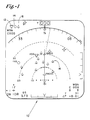
- FIG. 1 shows a typical cockpit display 10 including symbols 12, 14 and 16.
- Such displays, including the symbology are typically generated from data received from an onboard computer such as a digital map computer, for example.
- Such display systems must meet stringent requirements, such as updating the display up to 60 times per second, and this leads to limitations on the number of symbols which can be displayed at any given point in time. If such a system attempts to display too many symbols simultaneously, an excess data condition can arise which resultsin dimming and ultimately flickering of the display.
- the invention overcomes the perceived disadvantages of the prior art by providing a method in one aspect of the invention whereby a null symbol is introduced to prevent flashing when removing symbols to eliminate an excess data condition.
- a null symbol is a symbol which actually generates no display, that is, nothing appears on the screen when generating the null symbol. However, the null symbol does consume stroke time.
- the method of the invention is employed in a digital display system including a stroke scanning mechanism and comprises the steps of displaying symbology and increasing or decreasing the number of symbols displayed, including the null symbol depending upon comparisons of actual stroke time to a predetermined stroke time limit.
- the symbology is initially displayed by stroke scanning.
- the actual stroke time for displaying the symbology is measured.
- the actual stroke time is then compared with the predetermined stroke time limit to ascertain whether or not the time limit has been exceeded. If the stroke time limit is not exceeded and a null symbol is not present in the symbology displayed, a null symbol is added. If the stroke time limit is not exceeded and a null symbol is present in the displayed symbology, the number of symbols is increased. If the stroke timing limit is exceeded and a null symbol is present in the symbology displayed, the null symbol is removed. If the stroke time limit is exceeded and the null symbol is not present, a null symbol is added and the number of other visible symbols is decreased. The aforedescribed steps are repeated in a cyclical manner as long as the display is operating.
- a null symbol is always present and included in the symbology displayed.
- a first stroke time period is measured wherein the first time period occurs before displaying the null symbol and a second time period is measured after displaying the null symbol and including the time in which it takes to display thenull symbol. If the stroke time is exceeded before the null symbol is displayed, the number of other symbols is decreased. If the stroke time is not exceeded before the null symbol is displayed, the second time period is tested to determine whether the stroke time limit is exceeded after the display of the null symbol. If the second time period exceeds the stroke time limit, all symbols are retained including the null symbol and the process recycles. If the second measured time period does not exceed the stroke time limit, the number of symbols is increased according to predetermined priorities and the symbology is, again, displayed repeating the aforedescribed cycle.
- the present invention provides an adaptive symbology hysteresis method which prevents flashing of a symbol when used in the prioritized display symbology scheme.
- the invention prevents partial display of a symbol in the process of display at the termination of a minimum or fixed refresh period.
- the invention provides an adaptive symbology hysteresis method which dynamically limits the number of symbols displayed in order to maintain adherence to a fixed refresh period.
- the invention provides a method to avoid flashing of symbology in a digital display system through the employment of a null symbol.
- the invention provides a method which dynamically manages the number of symbols to maintain a minimum or fixed refresh period used in conjunction with a prioritized display symbology scheme.
- Figure 1 shows an example of an avionics cockpit display wherein the method of the invention is employed.
- FIG. 2 shows a flow chart which details the major steps of one aspect of the method of the invention.
- Figures 3A and 3B illustrate an example application of one aspect of the invention wherein hysteresis is used.
- Figures 4A and 4B illustrate an example of an application of a hysteresis equilibrium state as employed in one aspect of the method of the invention.
- Figure 5 is a graphical representation of the null symbol hysteresis scheme of the invention.
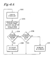
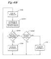
- Figures 6A and 6B are flow charts of other aspects of the invention using a non-hysteresis scheme wherein a null symbol is always present.
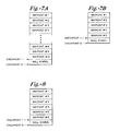
- FIGS 7A and 7B illustrate an example of an application using the non-hysteresis symbology method employed in an alternative aspect of the invention as illustrated in Figure 6A.
- Figure 8 illustrates the equilibrium state of the alternative aspect of the invention.
- FIG. 2 a flow chart of the major steps of one aspect of the invention is shown wherein adaptive symbology hysteresis is employed to dynamically manage the number of symbols displayed on a digital map system.
- the process of the invention maintains a minimum or fixed refresh period in conjunction with a prioritized display symbology scheme.
- the prioritized symbology scheme is provided in accordance with well-known methods.
- Various symbols such as the symbols shown in Figure 1 including waypoints 16, are prioritized in accordance with user defined requirements prior to being displayed.
- a predetermined number of a plurality of such symbols are displayed.
- the symbols are displayed typically through stroke scanning in a well known manner.
- the stroke scanning of the symbols displayed must be accomplished within a given predetermined refresh period.
- the refresh period may be on the order of 60 times per second. Therefore, an upper limit on the stroke time must be maintained in order to maximize the number of symbols displayed while avoiding flashing of symbols to the human eye.
- the system may try to display all of the symbols available or only a predetermined number of initial symbols at step 100.
- the actual stroke time that is the time it takes to actually stroke scan all of the displayed symbols, is measured.
- a determination is made as to whether or not there was enough stroke time to complete display of all of the symbols in the previous step.
- An alternative embodiment is, at step 102, to determine if all of the symbols were displayed during the minimum or fixed refresh period. If the stroke time limit has been exceeded or, in the alternative embodiment, all symbols were not displayed, the method of the invention proceeds to step 106. If the stroke time limit has not been exceeded, the method of the invention proceeds to step 114. Assuming the branch to step 106 is taken, the displayed symbology is tested for the presence of a null symbol. If a null symbol was used in the displayed symbology the method proceeds to step 108.
- step 110 the method of the invention proceeds to step 110.
- step 108 the number of symbols is decreased and the method proceeds to step 112 wherein the null symbol is added. The method then cycles back to step 100 and repeats. If the null symbol was not used, the method proceeds to step 110 where the null symbol is removed and the method cycles back to step 100.
- step 104 the stroke time limit was not exceeded, the method proceeds to step 114 wherein the presence of the null symbol is determined in a manner similar to that described with reference to step 106 above. If the null symbol was used, the method proceeds to step 116 wherein the number of displayed symbols is increased. If the null symbol was not used, the null symbol is added at step 118. The cycle then resumes with step 100 until the display is terminated.
- Figure 3A shows a prioritized series of waypoints numbered 1-10.
- the checkpoint indicated occurs at the end of the displayed available symbols.
- the symbols displayed as illustrated in Figure 3A do not include a null symbol. If it is assumed that the stroke limit is reached after displaying six symbols, the time period required for stroke scan display of waypoint symbols number 1-10 would exceed the stroke time limit.
- the example shown in Figure 3A would result in exiting step 104 at the "no" branch following that branch into step 106 and exiting step 106 at its "no" branch to step 108. Therefore, the number of symbols would be decreased and the null symbol would be added given the conditions shown in Figure 3A.
- Figures 4A and 4B illustrate some other possible conditions which may exist in the system and illustrate branches to other parts of the decision logic provided by the method of the invention.
- the stroke time limit will be exceeded at the checkpoint occurring after displaying the null symbol.
- this will result in branching through step 106 to step 110 wherein the null symbol is removed.
- the condition shown in Figure 4B will exist wherein the null symbol has been removed and the measurement of actual stroke time at the checkpoint in Figure 4B will result in a decision at step 104 that the stroke time has not been exceeded, thereby causing the process to branch to step 114.
- null symbol Since the null symbol is not used in step 114, it will be added at step 118. Note that this will then result again in a configuration shown in Figure 4A wherein the six waypoints and a null symbol are input into the display symbology step 100. In this way, an equilibrium state is reached wherein the null symbol is alternately added and removed from the symbology displayed, thereby maintaining the screen at an equilibrium state wherein six waypoints are continually displayed without causing any of the waypoint symbols to flash on the display screen.
- Figure 5 shows a graphical illustration of the principles employed by the method of the invention in the first aspect of the invention.
- the number of symbols actually displayed is illustrated on the vertical axis while the number of symbols to be displayed defines the horizontal axis.
- the stroke time limit is indicated as broken line STL.
- the null symbol hysteresis is represented by loop NS.
- Line SAD is a plot of the number of symbols actually displayed versus the number of symbols available for display. Note that as the stroke time limit is reached, the null signal loop prevents display of actual symbols which would exceed the stroke time limit.
- step 200 symbology is displayed always including a null symbol as part of the display.
- step 202 the process measures the actual stroke times before and after the null symbol is displayed resulting in first and second measured actual time periods. The process then continues to step 204 wherein the first time period measured from the time of the start of the display to the time just before display of the null symbol is compared with the stroke time limit. If the stroke time limit is exceeded at step 204, the process continues to step 208 and the number of actual symbols is decreased while retaining the null symbol.
- step 206 the process continues to step 206 wherein the second time period, which includes the first time period added to the time for stroke scanning the null signal, is compared against the stroke time limit. If the stroke time limit is exceeded by the second measured time period, the process branches back to step 200 and the number of symbols is not changed. If the stroke limit has not been exceeded after the null symbol is displayed, the "no" branch of step 206 is followed to step 216 and the number of symbols is increased by a predetermined number of increments. The process then cycles as long as necessary to display the symbology.
- step 200 symbology is displayed always including a null symbol as part of the display.
- step 202A the process determines if all of the non-null symbols were displayed and if the null symbol was displayed during the minimum or fixed refresh period. The process continues to step 204A wherein the stroke time limit is considered to be exceeded if all non-null symbols were not displayed. It all non-null symbols were not displayed, the process continues to step 208 and the number of actual symbols is decreased while retaining the null symbol.
- step 206A the stroke time limit is considered to be exceeded if the null symbol was not displayed. If the null symbol was not displayed, the process branches back to step 200 and the number of symbols is not changed. If the null symbol was displayed, the "yes" branch of step 206A is followed to step 216 and the number of symbols is increased by a predetermined number of increments. The process then cycles as long as necessary to display the symbology.
- Figures 7A, 7B and 8 show various examples illustrating the non-hysteresis symbology decrease, increase and equilibrium states of an alternate aspect of the invention.
- a set of waypoints 1-10 and a null symbol is shown as available for display at step 200.
- Checkpoint number 1 wherein a first time period is measured from waypoint number 1 through waypoint number 10 occurs immediately after the display of waypoint number 10 and immediately before the null symbol.
- Checkpoint number 2 is the point at which a second measurement is taken for a second time period which is inclusive of the time period measured in checkpoint number 1 plus the time period required to display the null symbol.
- the stroke limit will be exceeded at checkpoint number 1 and at checkpoint number 2.
- the process will branch through step 208 and the number of symbols will be decreased.
- FIG. 7B another illustrative example is shown wherein six symbols, including the null symbol, are available for display at step 200.
- the stroke limit allows for six symbols to be displayed, the stroke limit is not exceeded at either checkpoint number 1 or checkpoint number 2. Therefore, referring again to Figure 6A, the process will branch through step 216 and the number of symbols will be increased by adding a waypoint number 6, for example.
- Figure 8 shows the number of symbols available for display resulting from the processing of the example shown in Figure 7B as described above. Namely, the sixth waypoint has been added between waypoint number 5 and the null symbol. At this point, the stroke limit will be exceeded at checkpoint number 2 but not at checkpoint number 1. This will result in an equilibrium being reached whereby the process flow shown in Figure 6A will proceed through step 206 to the "yes" branch of 206 and the number of symbols will neither be increased nor decreased. The fact that the null symbol occurs after exceeding the time limit for stroke scanning is of no consequence on the display since the null symbol results in no visible display.
Landscapes
- Engineering & Computer Science (AREA)
- Radar, Positioning & Navigation (AREA)
- Remote Sensing (AREA)
- Physics & Mathematics (AREA)
- Computer Hardware Design (AREA)
- General Physics & Mathematics (AREA)
- Theoretical Computer Science (AREA)
- Numerical Control (AREA)
- Controls And Circuits For Display Device (AREA)
- Digital Computer Display Output (AREA)
Applications Claiming Priority (2)
| Application Number | Priority Date | Filing Date | Title |
|---|---|---|---|
| US50007690A | 1990-03-28 | 1990-03-28 | |
| US500076 | 1990-03-28 |
Publications (3)
| Publication Number | Publication Date |
|---|---|
| EP0449243A2 true EP0449243A2 (de) | 1991-10-02 |
| EP0449243A3 EP0449243A3 (en) | 1993-02-03 |
| EP0449243B1 EP0449243B1 (de) | 1996-08-14 |
Family
ID=23987943
Family Applications (1)
| Application Number | Title | Priority Date | Filing Date |
|---|---|---|---|
| EP91104840A Expired - Lifetime EP0449243B1 (de) | 1990-03-28 | 1991-03-27 | Verfahren zur Anzeige von Symbolen |
Country Status (5)
| Country | Link |
|---|---|
| US (1) | US5317331A (de) |
| EP (1) | EP0449243B1 (de) |
| JP (1) | JPH05119729A (de) |
| CA (1) | CA2035393A1 (de) |
| DE (1) | DE69121269T2 (de) |
Families Citing this family (3)
| Publication number | Priority date | Publication date | Assignee | Title |
|---|---|---|---|---|
| US6749120B2 (en) * | 2000-12-11 | 2004-06-15 | Cpo Technologies Corp. | Method and apparatus for scanning electronic barcodes |
| US20030115375A1 (en) * | 2001-12-17 | 2003-06-19 | Terry Robison | Methods and apparatus for delayed event dispatching |
| USD531186S1 (en) | 2003-03-03 | 2006-10-31 | Dr. Ing. H.C.F. Porsche Aktiengesellschaft | Icon for a vehicle cockpit display |
Family Cites Families (6)
| Publication number | Priority date | Publication date | Assignee | Title |
|---|---|---|---|---|
| US4070662A (en) * | 1975-11-11 | 1978-01-24 | Sperry Rand Corporation | Digital raster display generator for moving displays |
| US4511892A (en) * | 1982-06-25 | 1985-04-16 | Sperry Corporation | Variable refresh rate for stroke CRT displays |
| US4584574A (en) * | 1983-09-14 | 1986-04-22 | International Business Machines Corporation | Information display and editing system |
| US4631532A (en) * | 1984-04-02 | 1986-12-23 | Sperry Corporation | Raster display generator for hybrid display system |
| US4635050A (en) * | 1984-04-10 | 1987-01-06 | Sperry Corporation | Dynamic stroke priority generator for hybrid display |
| US4882577A (en) * | 1985-06-07 | 1989-11-21 | Hughes Aircraft Company | Calligraphic control for image superimposition |
-
1991
- 1991-01-31 CA CA002035393A patent/CA2035393A1/en not_active Abandoned
- 1991-03-19 JP JP3078353A patent/JPH05119729A/ja not_active Withdrawn
- 1991-03-27 EP EP91104840A patent/EP0449243B1/de not_active Expired - Lifetime
- 1991-03-27 DE DE69121269T patent/DE69121269T2/de not_active Expired - Fee Related
- 1991-10-25 US US07/782,914 patent/US5317331A/en not_active Expired - Lifetime
Also Published As
| Publication number | Publication date |
|---|---|
| DE69121269D1 (de) | 1996-09-19 |
| CA2035393A1 (en) | 1991-09-29 |
| EP0449243A3 (en) | 1993-02-03 |
| EP0449243B1 (de) | 1996-08-14 |
| DE69121269T2 (de) | 1997-01-23 |
| US5317331A (en) | 1994-05-31 |
| JPH05119729A (ja) | 1993-05-18 |
Similar Documents
| Publication | Publication Date | Title |
|---|---|---|
| US5652602A (en) | Fast serial data transmission using a CRT | |
| EP0738951B1 (de) | Verfahren und Vorrichtung zur Datenverarbeitung für Eingabe und Ausgabe von Ablaufdaten | |
| CA2220296A1 (en) | Calibrating optical data transmission frequency from crt | |
| US6812915B2 (en) | Liquid crystal display device | |
| US4380733A (en) | Frequency and speed display device | |
| KR880002089A (ko) | 복합문서 처리장치용 표시 제어장치 | |
| EP0708433A2 (de) | Verfahren und Einrichtung zum Steuern einer Anzeige | |
| KR970005937B1 (ko) | 데이타 인에이블 신호 입력시 엘.씨.디 제어신호 출력회로 | |
| EP0449243B1 (de) | Verfahren zur Anzeige von Symbolen | |
| EP0366124A1 (de) | Halbbild-Diskriminierschaltung | |
| EP3261522A1 (de) | Vorrichtung, verfahren und system für auflösungsabhängige grafische darstellung von signalen | |
| US4484189A (en) | Memoryless artificial horizon generator | |
| KR20020096896A (ko) | 표시 방법을 제어하기 위한 방법, 그 방법을 실시하기위한 표시용 신호 생성 장치, 표시 장치 및 표시 시스템 | |
| JP3263783B2 (ja) | ラスタ化制御方法 | |
| CN109269628B (zh) | 监测马达振动的方法、终端设备以及计算机可读存储介质 | |
| JPH1138047A (ja) | ディジタルグラフィクス表示装置におけるアナログ表示スルーレート輝度変動のシミュレーション | |
| CN119380669B (zh) | 显示面板的驱动方法、驱动关系的确定方法及相关装置 | |
| EP0246887B1 (de) | Pseudozustandssignalgenerator | |
| SU993313A1 (ru) | Устройство дл отображени информации на экране цветной электронно-лучевой трубки | |
| US20030234774A1 (en) | Supporting variable line length in digital display timing controllers using data enable signal | |
| SU739585A1 (ru) | Устройство дл отображени векторов на экране элт | |
| EP0782082A2 (de) | Vorrichtung zur seriellen Datenübertragung | |
| KR100212283B1 (ko) | 아이콘의 다계조 표시 기능을 구비한 문자표시용 액정 표시 장치 | |
| EP0318600A1 (de) | Signalausgangsanordnung | |
| JPS5836787B2 (ja) | 表示アドレス発生装置 |
Legal Events
| Date | Code | Title | Description |
|---|---|---|---|
| PUAI | Public reference made under article 153(3) epc to a published international application that has entered the european phase |
Free format text: ORIGINAL CODE: 0009012 |
|
| AK | Designated contracting states |
Kind code of ref document: A2 Designated state(s): DE FR GB IT |
|
| PUAL | Search report despatched |
Free format text: ORIGINAL CODE: 0009013 |
|
| AK | Designated contracting states |
Kind code of ref document: A3 Designated state(s): DE FR GB IT |
|
| 17P | Request for examination filed |
Effective date: 19930727 |
|
| 17Q | First examination report despatched |
Effective date: 19950502 |
|
| GRAG | Despatch of communication of intention to grant |
Free format text: ORIGINAL CODE: EPIDOS AGRA |
|
| GRAG | Despatch of communication of intention to grant |
Free format text: ORIGINAL CODE: EPIDOS AGRA |
|
| GRAG | Despatch of communication of intention to grant |
Free format text: ORIGINAL CODE: EPIDOS AGRA |
|
| GRAH | Despatch of communication of intention to grant a patent |
Free format text: ORIGINAL CODE: EPIDOS IGRA |
|
| GRAH | Despatch of communication of intention to grant a patent |
Free format text: ORIGINAL CODE: EPIDOS IGRA |
|
| GRAA | (expected) grant |
Free format text: ORIGINAL CODE: 0009210 |
|
| AK | Designated contracting states |
Kind code of ref document: B1 Designated state(s): DE FR GB IT |
|
| REF | Corresponds to: |
Ref document number: 69121269 Country of ref document: DE Date of ref document: 19960919 |
|
| ET | Fr: translation filed | ||
| ITF | It: translation for a ep patent filed | ||
| PG25 | Lapsed in a contracting state [announced via postgrant information from national office to epo] |
Ref country code: GB Effective date: 19970327 |
|
| PLBE | No opposition filed within time limit |
Free format text: ORIGINAL CODE: 0009261 |
|
| STAA | Information on the status of an ep patent application or granted ep patent |
Free format text: STATUS: NO OPPOSITION FILED WITHIN TIME LIMIT |
|
| 26N | No opposition filed | ||
| GBPC | Gb: european patent ceased through non-payment of renewal fee |
Effective date: 19970327 |
|
| PG25 | Lapsed in a contracting state [announced via postgrant information from national office to epo] |
Ref country code: FR Free format text: LAPSE BECAUSE OF NON-PAYMENT OF DUE FEES Effective date: 19971128 |
|
| PG25 | Lapsed in a contracting state [announced via postgrant information from national office to epo] |
Ref country code: DE Effective date: 19971202 |
|
| REG | Reference to a national code |
Ref country code: FR Ref legal event code: ST |
|
| PG25 | Lapsed in a contracting state [announced via postgrant information from national office to epo] |
Ref country code: IT Free format text: LAPSE BECAUSE OF NON-PAYMENT OF DUE FEES Effective date: 20050327 |