EP0448963B1 - Vorrichtung zur automatischen Überwachung und Regelung für kathodische Schutzsysteme in armiertem Beton - Google Patents
Vorrichtung zur automatischen Überwachung und Regelung für kathodische Schutzsysteme in armiertem Beton Download PDFInfo
- Publication number
- EP0448963B1 EP0448963B1 EP91102707A EP91102707A EP0448963B1 EP 0448963 B1 EP0448963 B1 EP 0448963B1 EP 91102707 A EP91102707 A EP 91102707A EP 91102707 A EP91102707 A EP 91102707A EP 0448963 B1 EP0448963 B1 EP 0448963B1
- Authority
- EP
- European Patent Office
- Prior art keywords
- potential
- cathodic
- voltage
- anode
- protection
- Prior art date
- Legal status (The legal status is an assumption and is not a legal conclusion. Google has not performed a legal analysis and makes no representation as to the accuracy of the status listed.)
- Expired - Lifetime
Links
- 238000004210 cathodic protection Methods 0.000 title claims abstract description 20
- 239000011150 reinforced concrete Substances 0.000 title claims abstract description 19
- 230000033228 biological regulation Effects 0.000 title claims abstract description 11
- 230000002787 reinforcement Effects 0.000 claims abstract description 15
- 239000004567 concrete Substances 0.000 claims description 16
- 238000005259 measurement Methods 0.000 claims description 12
- 238000000034 method Methods 0.000 claims description 9
- 239000004020 conductor Substances 0.000 claims description 8
- 238000013523 data management Methods 0.000 claims 1
- 239000002184 metal Substances 0.000 claims 1
- UFHFLCQGNIYNRP-UHFFFAOYSA-N Hydrogen Chemical compound [H][H] UFHFLCQGNIYNRP-UHFFFAOYSA-N 0.000 abstract description 4
- 229910052739 hydrogen Inorganic materials 0.000 abstract description 4
- 239000001257 hydrogen Substances 0.000 abstract description 4
- 238000012544 monitoring process Methods 0.000 abstract description 2
- 229910000831 Steel Inorganic materials 0.000 description 10
- 239000010959 steel Substances 0.000 description 10
- 238000005260 corrosion Methods 0.000 description 6
- 230000007797 corrosion Effects 0.000 description 6
- 229910021607 Silver chloride Inorganic materials 0.000 description 4
- 230000007613 environmental effect Effects 0.000 description 4
- HKZLPVFGJNLROG-UHFFFAOYSA-M silver monochloride Chemical compound [Cl-].[Ag+] HKZLPVFGJNLROG-UHFFFAOYSA-M 0.000 description 4
- RTAQQCXQSZGOHL-UHFFFAOYSA-N Titanium Chemical compound [Ti] RTAQQCXQSZGOHL-UHFFFAOYSA-N 0.000 description 3
- 239000011513 prestressed concrete Substances 0.000 description 3
- 239000010936 titanium Substances 0.000 description 3
- 229910052719 titanium Inorganic materials 0.000 description 3
- 238000005336 cracking Methods 0.000 description 2
- 238000013461 design Methods 0.000 description 2
- 238000010586 diagram Methods 0.000 description 2
- 230000010287 polarization Effects 0.000 description 2
- OKTJSMMVPCPJKN-UHFFFAOYSA-N Carbon Chemical compound [C] OKTJSMMVPCPJKN-UHFFFAOYSA-N 0.000 description 1
- VEXZGXHMUGYJMC-UHFFFAOYSA-M Chloride anion Chemical compound [Cl-] VEXZGXHMUGYJMC-UHFFFAOYSA-M 0.000 description 1
- 230000003213 activating effect Effects 0.000 description 1
- 239000000956 alloy Substances 0.000 description 1
- 229910045601 alloy Inorganic materials 0.000 description 1
- 239000010405 anode material Substances 0.000 description 1
- 239000010426 asphalt Substances 0.000 description 1
- QVGXLLKOCUKJST-UHFFFAOYSA-N atomic oxygen Chemical compound [O] QVGXLLKOCUKJST-UHFFFAOYSA-N 0.000 description 1
- 230000005540 biological transmission Effects 0.000 description 1
- 229910052799 carbon Inorganic materials 0.000 description 1
- 239000004568 cement Substances 0.000 description 1
- 238000000576 coating method Methods 0.000 description 1
- 238000011109 contamination Methods 0.000 description 1
- 230000001419 dependent effect Effects 0.000 description 1
- 238000001514 detection method Methods 0.000 description 1
- 238000009792 diffusion process Methods 0.000 description 1
- 230000000694 effects Effects 0.000 description 1
- 230000003203 everyday effect Effects 0.000 description 1
- 230000004907 flux Effects 0.000 description 1
- 239000000463 material Substances 0.000 description 1
- 150000004706 metal oxides Chemical class 0.000 description 1
- 229910003455 mixed metal oxide Inorganic materials 0.000 description 1
- 229910000510 noble metal Inorganic materials 0.000 description 1
- 229910052760 oxygen Inorganic materials 0.000 description 1
- 239000001301 oxygen Substances 0.000 description 1
- 150000003839 salts Chemical class 0.000 description 1
- 238000012360 testing method Methods 0.000 description 1
- 150000003608 titanium Chemical class 0.000 description 1
Images


Classifications
-
- C—CHEMISTRY; METALLURGY
- C23—COATING METALLIC MATERIAL; COATING MATERIAL WITH METALLIC MATERIAL; CHEMICAL SURFACE TREATMENT; DIFFUSION TREATMENT OF METALLIC MATERIAL; COATING BY VACUUM EVAPORATION, BY SPUTTERING, BY ION IMPLANTATION OR BY CHEMICAL VAPOUR DEPOSITION, IN GENERAL; INHIBITING CORROSION OF METALLIC MATERIAL OR INCRUSTATION IN GENERAL
- C23F—NON-MECHANICAL REMOVAL OF METALLIC MATERIAL FROM SURFACE; INHIBITING CORROSION OF METALLIC MATERIAL OR INCRUSTATION IN GENERAL; MULTI-STEP PROCESSES FOR SURFACE TREATMENT OF METALLIC MATERIAL INVOLVING AT LEAST ONE PROCESS PROVIDED FOR IN CLASS C23 AND AT LEAST ONE PROCESS COVERED BY SUBCLASS C21D OR C22F OR CLASS C25
- C23F13/00—Inhibiting corrosion of metals by anodic or cathodic protection
- C23F13/02—Inhibiting corrosion of metals by anodic or cathodic protection cathodic; Selection of conditions, parameters or procedures for cathodic protection, e.g. of electrical conditions
- C23F13/04—Controlling or regulating desired parameters
-
- C—CHEMISTRY; METALLURGY
- C23—COATING METALLIC MATERIAL; COATING MATERIAL WITH METALLIC MATERIAL; CHEMICAL SURFACE TREATMENT; DIFFUSION TREATMENT OF METALLIC MATERIAL; COATING BY VACUUM EVAPORATION, BY SPUTTERING, BY ION IMPLANTATION OR BY CHEMICAL VAPOUR DEPOSITION, IN GENERAL; INHIBITING CORROSION OF METALLIC MATERIAL OR INCRUSTATION IN GENERAL
- C23F—NON-MECHANICAL REMOVAL OF METALLIC MATERIAL FROM SURFACE; INHIBITING CORROSION OF METALLIC MATERIAL OR INCRUSTATION IN GENERAL; MULTI-STEP PROCESSES FOR SURFACE TREATMENT OF METALLIC MATERIAL INVOLVING AT LEAST ONE PROCESS PROVIDED FOR IN CLASS C23 AND AT LEAST ONE PROCESS COVERED BY SUBCLASS C21D OR C22F OR CLASS C25
- C23F2201/00—Type of materials to be protected by cathodic protection
- C23F2201/02—Concrete, e.g. reinforced
Definitions
- the present invention finds its application in the field of impressed current cathodic protection of reinforced concrete structures.
- Cathodic protection of reinforced concrete is used to prevent or to stop corrosion of metallic reinforcements.
- the most typical application field is in bridges, slabs, beams, piers, multi-store parkings garages, etc, - situated in cold regions, where corrosion is caused by de-icing salts, as well as in structures exposed to marine environment.
- This kind of systems is realized either using an anode structure typically having a net arrangement (i.e. titanium activated by noble metal oxides) or applying conductive coatings.
- the main characteristic of any cathodic protection system in reinforced concrete structures is to guarantee that the protection conditions be extended to the whole surface of reinforcements, without reaching over-protection conditions.
- this threshold value ranges around -0.9 V with respect to Ag/AgCl electrode (W.H.Hartt, P.K.Narayanan, T.Y.Chen, C.C.Kumira, "Cathodic Protection and Environmental Cracking of Prestressing Steel", CORROSION/89, paper n. 382, NACE, New La, Aprile 1989; R.N.Parkins et al., “Environmental Sensitive Cracking of Prestressing Steels", Corrosion Science 22, p. 379, 1982).
- the potential of the surface of reinforcements is not uniform, but varies from one to another point, depending on the position with respect to the anode surface and to surrounding reinforcements.
- the amount of the variations changes with operating and environmental conditions. For instance, during winter or in high atmospheric humidity conditions, for which the oxygen diffusion within concrete results difficult, such local variations may be very high.
- the present invention consists in a device able to check that protection conditions are reached (i.e. using the well-known 100 mV decay method) and to ensure that no over-protection conditions are achieved.
- the innovative idea has its base on the measurement of the potential of the anode, instead of the measurement of the potential of the protected structure (i.e. reinforcements) as it has been done up to now for the concrete cathodic protection applications.
- the present invention is based on some peculiar features regarding voltages involved in cathodic protection systems for concrete.
- Ec it should be ranged within an interval limited, on its lower side, by the above mentioned minimum value, that is in case of high strength steels, for pre-stressed or post-stressed reinforced concrete -0.90 V, whereas for standard steels used in reinforced concrete -1.1 V (all potential values are referred to Ag/AgCl electrode).
- Ea As far as Ea is concerned, it slowly rises in time, at least in the first years operation. In case of activated titanium, it passes, from an initial value of about 0.4 V to 0.7-0.9 V, or higher, a few years after (P. Pedeferri et al. "Cathodic protection of Steel in Concrete with Expanded Titanium Anode Net System", UK Corrosion Conference, Blackpool, England, 8-10 November). It can also vary with environmental conditions, particularly with temperature and therefore with seasons. However, unlike cathodic potential, Ea is generally uniform on all the anode surface. This uniformity depends on the use of the special distributors that reduce attenuation as well as on the particular electrocatalytic characteristics of the materials used.
- the ohmic drop Eohm has very low values, because of the low currents involved, except for in particularly dry concrete. It is mainly localized in close proximity of the anode, where current density is greater. The term of any ohmic drop different from the ohmic drop in proximity of the anode can therefore be disregarded (and this makes the whole system more conservative).
- the ohmic contribution localized on the anode is determined along with the anode potential by means of reference electrode placed between anode and cathode (i.e. the same electrode used to check that protection conditions are reached by means of 100 mV decay method can be utilized). Actually, the meaning of anode potential here considered, Ea,on results to be equal to Ea true + Eohm (see equation 1).
- Em ohmic drop in metallic conductors includes ohmic drops in the anodic feeding cables (ohmic drops in the rebars are negligible) and ohmic drops in anodic structures, i.e. the net and the relevant distribution strips. It depends on the flowing current.
- the present invention consists in a device for the control and regulation of the feeding unit in cathodic protection systems for reinforced concrete, that is based on the measurement of the feed voltage and of the anode potential instead of the cathodic potential, as it happens in traditional cathodic protection systems.
- This device is able to guarantee safe protection conditions of reinforcements, as far as overprotection is concerned.
- This device in its preferred embodiment, consists of a control unit where the following parameters are set: minimum protection potential (-0.90 or -1.1 V); initial voltage or current, Eo or Io; this control unit periodically determines: feed voltage, E, and anode potential Ea,on; the current involved and the ohmic drop contribution in metallic conductors, Em; moreover, it performs routine protection tests based, for instance, on 100 mV decay method.
- the control unit can be applied to systems operating both at “imposed voltage” (called “constant voltage”) and at “imposed current” (called “constant current”).
- control unit If system operates at "constant voltage", the control unit imposes the pre-established initial voltage, checks, based on one or more measurements of the cathodic potential and following traditional principle, that protection conditions of reinforcements be reached (i.e. using the well-known 100 mV decay criteria) and, if such conditions would not be reached, it adjusts the feed voltage in order to meet this requirement; then, it measures the anode potential, Ea,on, then it calculates the cathodic potential Ec in order to check that no overprotection conditions are achieved.
- a more accurate control can be realized if the anodic potential is taken as close as possible to the electrical connection of the power cables to the anodic structure, by means of an auxiliary, current free, electrical cable. In this case, in fact, the contribution of the ohmic drop in the cables is eliminated.
- control unit In case of feeding "at constant current", the control unit imposes a pre-established initial current and checks that protection conditions be reached without the occurrence of overprotection conditions. This latter control is carried out by means of a measurement of the feed voltage and the anode potential and of the calculation of the cathodic potential as per equation (2), that should be greater than the above-cited threshold values. If this threshold value results to exceed the cathodic potential, the control unit reduces the feed current so as to exclude overprotection conditions.
- the feeding unit imposes a constant voltage, E, calculated as the sum of the measured anode potential Ea,on of the cathodic potential Ec and of the ohmic contributions, Em, where Ec and Em contributions are pre-determined; the control and automatic regulation are performed by periodically measuring the potential of the anode structure Ea,on, and then re-calculating the new feed voltage, so as to keep the structure constantly under protection conditions, avoiding any overprotection risks.
- the anode potential Ea,on can be measured using several reference electrodes which are representative of zones with different concrete conductivity, when using such several electrodes, the control device should be able to properly process signals so as to obtain one value (i.e. the lowest value) to be entered in the sum for E calculation.
- the principle of the system relies mainly on the higher uniformity of the potential of the anodic structure, compared with the cathode.
- the device As a protection against possible failures that might take place in the circuits or in reference electrodes, the device is provided with a safety system which, when the feed voltage should reach a given Emax value, automatically brings the voltage back to a lower value Emin (i.e. 1.5 V), pre-established as well, simultaneously activating an alarm signal.
- Emin i.e. 1.5 V
- the device is realized as an "intelligent" system, such as for instance a microprocessor or a personal computer, equipped with an adequate number of analogical inputs and outputs, able to run a program for the management of the system and of variables: input data acquisition, measurement of the anode potential, calculation of the feed voltage etc:
- the system is then connected to the feeding unit, to which it transmits the order for the adjustment of the voltage or feeding current, and if necessary, to a data acquisition unit for storing all systems current data or to a data transmission unit.
- a system for cathodic protection of a pre-stressed concrete bridge deck consists of several units, each one with its own transformer-rectifier feeding a mixed metal oxide activated titaniun net, having a rectangular surface of 360 m2.
- Connections between power cables and anodic structure are located at one side of the net.
- a reference electrode has been placed in correspondance of the power connection side, positioned close to the titanium net.
- a second reference electrode of the same type has been placed at the opposite side, close to the rebar.
- the anodic structure has been designed to have a maximum ohmic drop in metallic conductors lower than 100 mV at the maximum design current density, equal to 20 mA/m2 referred to the concrete surface.
- Free corrosion potential of rebar measured by means of fixed reference electrodes as well as by portable ones, ranges between -0.1 and -0.25 V vs Ag/AgCl, while the potential of the anodic structures in same conditions is equal to -0.18 V.
- Power unit is a "constant voltage" type and it is controlled by an automatic regulation device which operates as follows.
- Current output is equal to 3.2 A, corresponding to a current density of 9 mA/m2.
- the control unit automatically increased the applied potential from 1.0 to 1.2 V, step by step, recalculating the cathode potential, Ec, equal to -0.45 V, and verifying the compliance with above written inequality, which again is verified.
- the device reduces the applied voltage and repeats control operations.
- Fig. 1 reports the flux diagram of the operation carried out by the control unit.
- Reinforced concrete slab protected using a "constant current" feeding system No high strength steel is present.
- the system imposes an initial current density of 10 mA/m2 (based on experience, the initial current required is ranged between 10 and 20 mA/m2) and calculates circulating current and ohmic drops in wires.
- the system adjusts current so that the protection conditions are reached, based in 100 mV decay method; in the negative, it adjusts current until reaching protection conditions.
- Fig. 2 reports the diagram of the device.
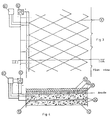
- Figs. 3 and 4 illustrate the main elements of a cathodic protection system for reinforced concrete structure, following the present invention.
- Fig. 3 is a plan view of a cathodically protected bridge slab, showing the anode net structure;
- fig. 4 is a sectional view along the line IV-IV of fig. 3.
- the slab consists in a metallic reinforcement 10, behaving as cathode, buried in concrete 20, above which an anode net structure is laid.
- the anode net 30 is covered by a layer of cement 40, over which the asphalt 50 is then laid.
- the necessary potential difference between anode and cathode 10 is maintained by means of a feeder 60 able to operate at both constant voltage and constant current.
- At least one reference electrode 70 is installed, connected to a control unit 80, that intervenes on the feeder 60 for necessary adjustments, in order to keep the system in proper protection conditions, avoiding any overprotection risks.
Landscapes
- Chemical & Material Sciences (AREA)
- Engineering & Computer Science (AREA)
- Materials Engineering (AREA)
- Mechanical Engineering (AREA)
- Metallurgy (AREA)
- Organic Chemistry (AREA)
- Prevention Of Electric Corrosion (AREA)
- Control Of Non-Electrical Variables (AREA)
Claims (10)
- Vorrichtung zur Überwachung und automatischen Regulierung der Speiseeinheit (60) eines kathodischen Schutzsystems mit vorgegebenem Strom, in einem Stahlbetonbauwerk,
mit einer metallischen Bewehrung (10), die sich als Kathode verhält, der eine Anodenkonstruktion (30) zugeordnet ist, dadurch gekennzeichnet, daß diese Vorrichtung geeignet ist, die Speisespannung, die als die Summe von Anodenspannung Ea, Kathodenspannung Ec, ohmschen Spannungsabfällen in metallischen Leitern Em und ohmschen Spannungsabfällen in Beton Eohm:
- Vorrichtung nach Anspruch 1, dadurch gekennzeichnet, daß die Speiseeinheit (60) bei konstanter Spannung oder bei konstantem Strom arbeitet.
- Vorrichtung nach Anspruch 1, dadurch gekennzeichnet, daß die Bezugselektrode im Stahlbetonbauwerk eingeschlossen und zwischen der kathodischen und anodischen Konstruktion angeordnet ist.
- Vorrichtung nach Anspruch 1, dadurch gekennzeichnet, daß die Anodenkonstruktion eine Netzkonstruktion ist, welche im Stahlbeton eingeschlossen ist.
- Vorrichtung nach einem der vorhergehenden Ansprüche, bei der die Überwachungsvorrichtung (80) an mehrere Bezugselektroden (70) angeschlossen und fähig ist, Signale richtig zu verarbeiten, zum Beispiel die mittlere quadratische Regelabweichung zu berechnen, einen Teil der Messung auszuwählen, die Zuverlässigkeit der Messungen einzuschätzen.
- Vorrichtung nach einem der vorhergehenden Ansprüche, dadurch gekennzeichnet, daß dann, wenn die Speisespannung oder der Speisestrom einen vorbestimmten Schwellenwert erreicht, die Überwachungsvorrichtung (80) automatisch ein Alarmsignal aktiviert und die Spannung oder den Strom auf einen vorbestimmten Minimumwert zurückbringt.
- Vorrichtung nach einem der vorhergehenden Ansprüche, umfassend eine Speichereinheit, auf welche die Vorrichtung (80) periodisch alle Systemparameter überträgt.
- Vorrichtung nach einem der vorhergehenden Ansprüche, bei der die Überwachungs- und Regulierungsvorrichtung (80) aus einem "intelligenten System", wie einem Mikroprozessor oder einem Personalcomputer besteht, der mit einer ausreichenden Anzahl von Eingängen und Ausgängen ausgerüstet ist, geeignet ist, ein Programm von Datenmanagement und Datenverarbeitung zu betreiben, mittels der angeschlossenen Bezugselektroden ein oder mehrere Spannungsmessungen zu erhalten und die Speiseeinheit (10) des kathodischen Schutzsystems mit ordnungsgemäß verarbeiteten Betriebsparametern zu versorgen.
- Schutzsystem mit vorgegebenem Strom, umfassend eine Speiseeinheit (60), die geeignet ist, um eine Potentialdifferenz zwischen der kathodischen Bewehrung (10) und einer Anodenkonstruktion (30) des Stahlbetonbauwerkes zu erzeugen, gekennzeichnet durch eine Vorrichtung (80) zur Überwachung und Regulierung der Speiseeinheit (60), wie in irgendeinem der Ansprüche 1 bis 8 beansprucht, um einen ausreichenden Schutz der kathodischen Konstruktion (10) ohne irgendein Überschutz-Risiko zu gewährleisten.
- Verfahren zur Überwachung und automatischen Regulierung der Speisung von kathodischen Schutzsystemen mit vorgegebenem Strom in einem Stahlbetonbauwerk, durchgeführt mit einer Vorrichtung nach Anspruch 1, umfassend eine indirekte Messung des Kathodenpotentials auf dessen Basis notwendige Anpassungen der Speisung durchgeführt werden können, um einen ausreichenden Schutz der Metallkonstruktion unter Vermeidung jeglichen Überschutz-Risikos sicherzustellen, wobei die indirekte Messung des Kathodenpotentials als Differenz zwischen der Speisespannung E, dem gemessenen Anodenpotential Ea,on und ohmschen Spannungsabfällen in Metalleitern Em unter Verwendung von einer oder mehreren Bezugselektroden (70) durchgeführt wird.
Applications Claiming Priority (2)
| Application Number | Priority Date | Filing Date | Title |
|---|---|---|---|
| IT1948490 | 1990-02-26 | ||
| IT19484A IT1239344B (it) | 1990-02-26 | 1990-02-26 | Dispositivo di controllo e di regolazione automatica dei sistemi di protezione catodica di strutture in cemento armato |
Publications (2)
| Publication Number | Publication Date |
|---|---|
| EP0448963A1 EP0448963A1 (de) | 1991-10-02 |
| EP0448963B1 true EP0448963B1 (de) | 1995-05-03 |
Family
ID=11158418
Family Applications (1)
| Application Number | Title | Priority Date | Filing Date |
|---|---|---|---|
| EP91102707A Expired - Lifetime EP0448963B1 (de) | 1990-02-26 | 1991-02-25 | Vorrichtung zur automatischen Überwachung und Regelung für kathodische Schutzsysteme in armiertem Beton |
Country Status (6)
| Country | Link |
|---|---|
| US (1) | US5225058A (de) |
| EP (1) | EP0448963B1 (de) |
| AT (1) | ATE122105T1 (de) |
| CA (1) | CA2036863C (de) |
| DE (1) | DE69109356T2 (de) |
| IT (1) | IT1239344B (de) |
Families Citing this family (18)
| Publication number | Priority date | Publication date | Assignee | Title |
|---|---|---|---|---|
| JP3040613B2 (ja) * | 1992-10-07 | 2000-05-15 | 大日本塗料株式会社 | 鉄筋コンクリート構造物の防食方法 |
| US5366670A (en) * | 1993-05-20 | 1994-11-22 | Giner, Inc. | Method of imparting corrosion resistance to reinforcing steel in concrete structures |
| US5532025A (en) * | 1993-07-23 | 1996-07-02 | Kinlen; Patrick J. | Corrosion inhibiting compositions |
| US5650060A (en) * | 1994-01-28 | 1997-07-22 | Minnesota Mining And Manufacturing Company | Ionically conductive agent, system for cathodic protection of galvanically active metals, and method and apparatus for using same |
| RU2149220C1 (ru) * | 1997-11-11 | 2000-05-20 | Центральный научно-исследовательский институт конструкционных материалов "Прометей" | Устройство для питания и автоматического регулирования выходного тока системы катодной защиты от коррозии металлоконструкций |
| US6690182B2 (en) * | 2000-07-19 | 2004-02-10 | Virginia Technologies, Inc | Embeddable corrosion monitoring-instrument for steel reinforced structures |
| US6419816B1 (en) * | 2000-10-18 | 2002-07-16 | Cor/Sci, Llc. | Cathodic protection of steel in reinforced concrete with electroosmotic treatment |
| US6387244B1 (en) * | 2000-10-18 | 2002-05-14 | Cor/Sci, Llc. | Cathodic protection of reinforced concrete with impregnated corrosion inhibitor |
| US7064459B1 (en) * | 2001-08-20 | 2006-06-20 | Brunswick Corporation | Method of inhibiting corrosion of a component of a marine vessel |
| EP1777322A1 (de) * | 2005-10-18 | 2007-04-25 | Technische Universiteit Delft | Vorrichtung und Verfahren für kathodischen Korrosionsschutz für eine stahlarmierte Betonstruktur |
| CN101738368B (zh) * | 2008-11-18 | 2012-10-03 | 北京市水利规划设计研究院 | Pccp管阴极保护测试探头及测试方法 |
| GB2474084A (en) * | 2009-10-13 | 2011-04-06 | Aish Technologies Ltd | Impressed current cathodic protection (ICCP) |
| KR101347707B1 (ko) * | 2011-10-28 | 2014-01-06 | 주식회사 화승알앤에이 | 외부전원식 음극방식 및 희생양극식 음극방식 기술을 이용하는 해상 콘크리트 구조물의 하이브리드 음극 방식 시스템 |
| US20150068919A1 (en) * | 2012-04-11 | 2015-03-12 | Anode Engineering Pty Ltd | Cathodic protection system |
| WO2014179311A2 (en) | 2013-04-29 | 2014-11-06 | Transistor Devices, Inc. D/B/A Tdi Power | Systems and methods for impressed current cathodic protection |
| CN104005032B (zh) * | 2014-05-08 | 2016-08-24 | 青岛双瑞海洋环境工程股份有限公司 | 预应力钢筒混凝土管道的阴极保护测试探头和制备方法 |
| US11261530B2 (en) * | 2019-03-11 | 2022-03-01 | Prorbar, Inc. | Cathodic protection system and miniaturized constant current rectifier |
| CN114703480B (zh) * | 2022-04-15 | 2024-03-22 | 青岛雅合科技发展有限公司 | 区域阴极保护控制方法 |
Family Cites Families (8)
| Publication number | Priority date | Publication date | Assignee | Title |
|---|---|---|---|---|
| US3208925A (en) * | 1960-01-07 | 1965-09-28 | Continental Oil Co | Anodic protection against corrosion |
| BE614735A (de) * | 1961-03-07 | |||
| US3714004A (en) * | 1970-12-02 | 1973-01-30 | Continental Oil Co | Method and apparatus for cathodic protection |
| US4255241A (en) * | 1979-05-10 | 1981-03-10 | Kroon David H | Cathodic protection apparatus and method for steel reinforced concrete structures |
| GB2140456A (en) * | 1982-12-02 | 1984-11-28 | Taywood Engineering Limited | Cathodic protection |
| US4592818A (en) * | 1983-09-12 | 1986-06-03 | Outboard Marine Corporation | Cathodic protection system |
| DE3419612C2 (de) * | 1984-05-25 | 1986-06-12 | Felten & Guilleaume Energietechnik GmbH, 5000 Köln | Verfahren und Einrichtung zur Überwachung des kathodischen Korrosionsschutzes |
| US4855024A (en) * | 1986-09-16 | 1989-08-08 | Raychem Corporation | Mesh electrodes and clips for use in preparing them |
-
1990
- 1990-02-26 IT IT19484A patent/IT1239344B/it active IP Right Grant
-
1991
- 1991-02-22 US US07/659,269 patent/US5225058A/en not_active Expired - Fee Related
- 1991-02-25 EP EP91102707A patent/EP0448963B1/de not_active Expired - Lifetime
- 1991-02-25 CA CA002036863A patent/CA2036863C/en not_active Expired - Fee Related
- 1991-02-25 AT AT91102707T patent/ATE122105T1/de not_active IP Right Cessation
- 1991-02-25 DE DE69109356T patent/DE69109356T2/de not_active Expired - Fee Related
Also Published As
| Publication number | Publication date |
|---|---|
| US5225058A (en) | 1993-07-06 |
| IT9019484A0 (it) | 1990-02-26 |
| DE69109356D1 (de) | 1995-06-08 |
| DE69109356T2 (de) | 1996-01-11 |
| IT1239344B (it) | 1993-10-20 |
| CA2036863C (en) | 2001-01-23 |
| EP0448963A1 (de) | 1991-10-02 |
| ATE122105T1 (de) | 1995-05-15 |
| IT9019484A1 (it) | 1991-08-26 |
| CA2036863A1 (en) | 1991-08-27 |
Similar Documents
| Publication | Publication Date | Title |
|---|---|---|
| EP0448963B1 (de) | Vorrichtung zur automatischen Überwachung und Regelung für kathodische Schutzsysteme in armiertem Beton | |
| Elsener | Macrocell corrosion of steel in concrete–implications for corrosion monitoring | |
| Vennesland et al. | Recommendation of Rilem TC 154-EMC:“Electrochemical techniques for measuring corrosion in concrete”—measurements with embedded probes | |
| US20020134690A1 (en) | Doubly-protected reinforcing members in concrete | |
| Feliú et al. | Multiple-electrode method for estimating the polarization resistance in large structures | |
| Schiegg et al. | On-line monitoring of corrosion in reinforced concrete structures | |
| EP0593168A1 (de) | Methode und Gerät zur Messung von lokalisierten Korrosionstaten unter Depots oder Metallkorrisionsraten unter losen Depots in Kühlwassersystemen | |
| Bennett et al. | Cathodic protection of concrete bridges: a manual of practice | |
| Evitts et al. | Cathodic protection | |
| Broomfield et al. | Cathodic Protection for Reinforced Concrete: It's application to buildings and marine structures | |
| US20240279817A1 (en) | Methods for controlling and monitoring the degree of cathodic protection for metal structures and buried pipelines using coupled multielectrode sensors | |
| US6582587B1 (en) | Cathodic protection design method, current mapping and system | |
| Vrable¹ | Reinforcing Steel in Concrete | |
| Bennett et al. | Technical alert: criteria for the cathodic protection of reinforced concrete bridge elements | |
| Bazzoni et al. | A New Approach for Automatic Control and Monitoring of Cathodically Protected Reinforced Concrete Structures | |
| Davies et al. | Cathodic protection mechanism and a review of criteria | |
| Millard | CORROSION RATE MEASUREMENT OF IN-SITU REINFORCED CONCRETE STRUCTURES. | |
| DK171925B1 (da) | Fremgangsmåde til bestemmelse af korrosionshastigheden i armeret beton | |
| EP0693681A1 (de) | Methode und Gerät zur Messung des ohmischen abfallfreien Potentials und zur Beschichtungsintegrität in Anwesenheit von Streuströmen | |
| Bazzoni et al. | Field application of cathodic prevention on reinforced concrete structures | |
| van den Hondel et al. | Lessons learned from a case of concrete damage under cathodic protection of steel in concrete | |
| Sagüés et al. | An approach for the evaluation of performance of point anodes for corrosion prevention of reinforcing steel in concrete repairs | |
| Broomfield | Monitoring cathodic protection in concrete and masonry structures | |
| Debaene et al. | Effect of chloride concentration on the performance of impressed current cathodic protection (ICCP) for reinforced concrete: experimental research versus numerical modelling | |
| Barkai | A General Overview of Cathodic Protection in Reinforced Concrete |
Legal Events
| Date | Code | Title | Description |
|---|---|---|---|
| PUAI | Public reference made under article 153(3) epc to a published international application that has entered the european phase |
Free format text: ORIGINAL CODE: 0009012 |
|
| AK | Designated contracting states |
Kind code of ref document: A1 Designated state(s): AT BE CH DE DK ES FR GB GR IT LI LU NL SE |
|
| 17P | Request for examination filed |
Effective date: 19920311 |
|
| 17Q | First examination report despatched |
Effective date: 19940204 |
|
| GRAA | (expected) grant |
Free format text: ORIGINAL CODE: 0009210 |
|
| AK | Designated contracting states |
Kind code of ref document: B1 Designated state(s): AT BE CH DE DK ES FR GB GR IT LI LU NL SE |
|
| PG25 | Lapsed in a contracting state [announced via postgrant information from national office to epo] |
Ref country code: NL Free format text: LAPSE BECAUSE OF FAILURE TO SUBMIT A TRANSLATION OF THE DESCRIPTION OR TO PAY THE FEE WITHIN THE PRESCRIBED TIME-LIMIT Effective date: 19950503 Ref country code: GR Free format text: LAPSE BECAUSE OF FAILURE TO SUBMIT A TRANSLATION OF THE DESCRIPTION OR TO PAY THE FEE WITHIN THE PRESCRIBED TIME-LIMIT Effective date: 19950503 Ref country code: FR Effective date: 19950503 Ref country code: ES Free format text: THE PATENT HAS BEEN ANNULLED BY A DECISION OF A NATIONAL AUTHORITY Effective date: 19950503 Ref country code: DK Effective date: 19950503 Ref country code: BE Effective date: 19950503 Ref country code: AT Effective date: 19950503 |
|
| REF | Corresponds to: |
Ref document number: 122105 Country of ref document: AT Date of ref document: 19950515 Kind code of ref document: T |
|
| ITF | It: translation for a ep patent filed | ||
| REF | Corresponds to: |
Ref document number: 69109356 Country of ref document: DE Date of ref document: 19950608 |
|
| PG25 | Lapsed in a contracting state [announced via postgrant information from national office to epo] |
Ref country code: SE Effective date: 19950803 |
|
| EN | Fr: translation not filed | ||
| NLV1 | Nl: lapsed or annulled due to failure to fulfill the requirements of art. 29p and 29m of the patents act | ||
| PG25 | Lapsed in a contracting state [announced via postgrant information from national office to epo] |
Ref country code: LU Free format text: LAPSE BECAUSE OF NON-PAYMENT OF DUE FEES Effective date: 19960229 |
|
| PLBE | No opposition filed within time limit |
Free format text: ORIGINAL CODE: 0009261 |
|
| STAA | Information on the status of an ep patent application or granted ep patent |
Free format text: STATUS: NO OPPOSITION FILED WITHIN TIME LIMIT |
|
| 26N | No opposition filed | ||
| REG | Reference to a national code |
Ref country code: CH Ref legal event code: PUE Owner name: NUOVA POLMET CATHODIC PROTECTION S.R.L. TRANSFER- |
|
| PGFP | Annual fee paid to national office [announced via postgrant information from national office to epo] |
Ref country code: GB Payment date: 20000222 Year of fee payment: 10 |
|
| PG25 | Lapsed in a contracting state [announced via postgrant information from national office to epo] |
Ref country code: GB Free format text: LAPSE BECAUSE OF NON-PAYMENT OF DUE FEES Effective date: 20010225 |
|
| GBPC | Gb: european patent ceased through non-payment of renewal fee |
Effective date: 20010225 |
|
| PGFP | Annual fee paid to national office [announced via postgrant information from national office to epo] |
Ref country code: CH Payment date: 20040217 Year of fee payment: 14 |
|
| PGFP | Annual fee paid to national office [announced via postgrant information from national office to epo] |
Ref country code: DE Payment date: 20040407 Year of fee payment: 14 |
|
| PG25 | Lapsed in a contracting state [announced via postgrant information from national office to epo] |
Ref country code: IT Free format text: LAPSE BECAUSE OF NON-PAYMENT OF DUE FEES;WARNING: LAPSES OF ITALIAN PATENTS WITH EFFECTIVE DATE BEFORE 2007 MAY HAVE OCCURRED AT ANY TIME BEFORE 2007. THE CORRECT EFFECTIVE DATE MAY BE DIFFERENT FROM THE ONE RECORDED. Effective date: 20050225 |
|
| PG25 | Lapsed in a contracting state [announced via postgrant information from national office to epo] |
Ref country code: LI Free format text: LAPSE BECAUSE OF NON-PAYMENT OF DUE FEES Effective date: 20050228 Ref country code: CH Free format text: LAPSE BECAUSE OF NON-PAYMENT OF DUE FEES Effective date: 20050228 |
|
| PG25 | Lapsed in a contracting state [announced via postgrant information from national office to epo] |
Ref country code: DE Free format text: LAPSE BECAUSE OF NON-PAYMENT OF DUE FEES Effective date: 20050901 |
|
| REG | Reference to a national code |
Ref country code: CH Ref legal event code: PL |