EP0448963B1 - Control and automatic regulation device for cathodic protection systems in reinforced concrete structures - Google Patents
Control and automatic regulation device for cathodic protection systems in reinforced concrete structures Download PDFInfo
- Publication number
- EP0448963B1 EP0448963B1 EP91102707A EP91102707A EP0448963B1 EP 0448963 B1 EP0448963 B1 EP 0448963B1 EP 91102707 A EP91102707 A EP 91102707A EP 91102707 A EP91102707 A EP 91102707A EP 0448963 B1 EP0448963 B1 EP 0448963B1
- Authority
- EP
- European Patent Office
- Prior art keywords
- potential
- cathodic
- voltage
- anode
- protection
- Prior art date
- Legal status (The legal status is an assumption and is not a legal conclusion. Google has not performed a legal analysis and makes no representation as to the accuracy of the status listed.)
- Expired - Lifetime
Links
Images


Classifications
-
- C—CHEMISTRY; METALLURGY
- C23—COATING METALLIC MATERIAL; COATING MATERIAL WITH METALLIC MATERIAL; CHEMICAL SURFACE TREATMENT; DIFFUSION TREATMENT OF METALLIC MATERIAL; COATING BY VACUUM EVAPORATION, BY SPUTTERING, BY ION IMPLANTATION OR BY CHEMICAL VAPOUR DEPOSITION, IN GENERAL; INHIBITING CORROSION OF METALLIC MATERIAL OR INCRUSTATION IN GENERAL
- C23F—NON-MECHANICAL REMOVAL OF METALLIC MATERIAL FROM SURFACE; INHIBITING CORROSION OF METALLIC MATERIAL OR INCRUSTATION IN GENERAL; MULTI-STEP PROCESSES FOR SURFACE TREATMENT OF METALLIC MATERIAL INVOLVING AT LEAST ONE PROCESS PROVIDED FOR IN CLASS C23 AND AT LEAST ONE PROCESS COVERED BY SUBCLASS C21D OR C22F OR CLASS C25
- C23F13/00—Inhibiting corrosion of metals by anodic or cathodic protection
- C23F13/02—Inhibiting corrosion of metals by anodic or cathodic protection cathodic; Selection of conditions, parameters or procedures for cathodic protection, e.g. of electrical conditions
- C23F13/04—Controlling or regulating desired parameters
-
- C—CHEMISTRY; METALLURGY
- C23—COATING METALLIC MATERIAL; COATING MATERIAL WITH METALLIC MATERIAL; CHEMICAL SURFACE TREATMENT; DIFFUSION TREATMENT OF METALLIC MATERIAL; COATING BY VACUUM EVAPORATION, BY SPUTTERING, BY ION IMPLANTATION OR BY CHEMICAL VAPOUR DEPOSITION, IN GENERAL; INHIBITING CORROSION OF METALLIC MATERIAL OR INCRUSTATION IN GENERAL
- C23F—NON-MECHANICAL REMOVAL OF METALLIC MATERIAL FROM SURFACE; INHIBITING CORROSION OF METALLIC MATERIAL OR INCRUSTATION IN GENERAL; MULTI-STEP PROCESSES FOR SURFACE TREATMENT OF METALLIC MATERIAL INVOLVING AT LEAST ONE PROCESS PROVIDED FOR IN CLASS C23 AND AT LEAST ONE PROCESS COVERED BY SUBCLASS C21D OR C22F OR CLASS C25
- C23F2201/00—Type of materials to be protected by cathodic protection
- C23F2201/02—Concrete, e.g. reinforced
Definitions
- the present invention finds its application in the field of impressed current cathodic protection of reinforced concrete structures.
- Cathodic protection of reinforced concrete is used to prevent or to stop corrosion of metallic reinforcements.
- the most typical application field is in bridges, slabs, beams, piers, multi-store parkings garages, etc, - situated in cold regions, where corrosion is caused by de-icing salts, as well as in structures exposed to marine environment.
- This kind of systems is realized either using an anode structure typically having a net arrangement (i.e. titanium activated by noble metal oxides) or applying conductive coatings.
- the main characteristic of any cathodic protection system in reinforced concrete structures is to guarantee that the protection conditions be extended to the whole surface of reinforcements, without reaching over-protection conditions.
- this threshold value ranges around -0.9 V with respect to Ag/AgCl electrode (W.H.Hartt, P.K.Narayanan, T.Y.Chen, C.C.Kumira, "Cathodic Protection and Environmental Cracking of Prestressing Steel", CORROSION/89, paper n. 382, NACE, New La, Aprile 1989; R.N.Parkins et al., “Environmental Sensitive Cracking of Prestressing Steels", Corrosion Science 22, p. 379, 1982).
- the potential of the surface of reinforcements is not uniform, but varies from one to another point, depending on the position with respect to the anode surface and to surrounding reinforcements.
- the amount of the variations changes with operating and environmental conditions. For instance, during winter or in high atmospheric humidity conditions, for which the oxygen diffusion within concrete results difficult, such local variations may be very high.
- the present invention consists in a device able to check that protection conditions are reached (i.e. using the well-known 100 mV decay method) and to ensure that no over-protection conditions are achieved.
- the innovative idea has its base on the measurement of the potential of the anode, instead of the measurement of the potential of the protected structure (i.e. reinforcements) as it has been done up to now for the concrete cathodic protection applications.
- the present invention is based on some peculiar features regarding voltages involved in cathodic protection systems for concrete.
- Ec it should be ranged within an interval limited, on its lower side, by the above mentioned minimum value, that is in case of high strength steels, for pre-stressed or post-stressed reinforced concrete -0.90 V, whereas for standard steels used in reinforced concrete -1.1 V (all potential values are referred to Ag/AgCl electrode).
- Ea As far as Ea is concerned, it slowly rises in time, at least in the first years operation. In case of activated titanium, it passes, from an initial value of about 0.4 V to 0.7-0.9 V, or higher, a few years after (P. Pedeferri et al. "Cathodic protection of Steel in Concrete with Expanded Titanium Anode Net System", UK Corrosion Conference, Blackpool, England, 8-10 November). It can also vary with environmental conditions, particularly with temperature and therefore with seasons. However, unlike cathodic potential, Ea is generally uniform on all the anode surface. This uniformity depends on the use of the special distributors that reduce attenuation as well as on the particular electrocatalytic characteristics of the materials used.
- the ohmic drop Eohm has very low values, because of the low currents involved, except for in particularly dry concrete. It is mainly localized in close proximity of the anode, where current density is greater. The term of any ohmic drop different from the ohmic drop in proximity of the anode can therefore be disregarded (and this makes the whole system more conservative).
- the ohmic contribution localized on the anode is determined along with the anode potential by means of reference electrode placed between anode and cathode (i.e. the same electrode used to check that protection conditions are reached by means of 100 mV decay method can be utilized). Actually, the meaning of anode potential here considered, Ea,on results to be equal to Ea true + Eohm (see equation 1).
- Em ohmic drop in metallic conductors includes ohmic drops in the anodic feeding cables (ohmic drops in the rebars are negligible) and ohmic drops in anodic structures, i.e. the net and the relevant distribution strips. It depends on the flowing current.
- the present invention consists in a device for the control and regulation of the feeding unit in cathodic protection systems for reinforced concrete, that is based on the measurement of the feed voltage and of the anode potential instead of the cathodic potential, as it happens in traditional cathodic protection systems.
- This device is able to guarantee safe protection conditions of reinforcements, as far as overprotection is concerned.
- This device in its preferred embodiment, consists of a control unit where the following parameters are set: minimum protection potential (-0.90 or -1.1 V); initial voltage or current, Eo or Io; this control unit periodically determines: feed voltage, E, and anode potential Ea,on; the current involved and the ohmic drop contribution in metallic conductors, Em; moreover, it performs routine protection tests based, for instance, on 100 mV decay method.
- the control unit can be applied to systems operating both at “imposed voltage” (called “constant voltage”) and at “imposed current” (called “constant current”).
- control unit If system operates at "constant voltage", the control unit imposes the pre-established initial voltage, checks, based on one or more measurements of the cathodic potential and following traditional principle, that protection conditions of reinforcements be reached (i.e. using the well-known 100 mV decay criteria) and, if such conditions would not be reached, it adjusts the feed voltage in order to meet this requirement; then, it measures the anode potential, Ea,on, then it calculates the cathodic potential Ec in order to check that no overprotection conditions are achieved.
- a more accurate control can be realized if the anodic potential is taken as close as possible to the electrical connection of the power cables to the anodic structure, by means of an auxiliary, current free, electrical cable. In this case, in fact, the contribution of the ohmic drop in the cables is eliminated.
- control unit In case of feeding "at constant current", the control unit imposes a pre-established initial current and checks that protection conditions be reached without the occurrence of overprotection conditions. This latter control is carried out by means of a measurement of the feed voltage and the anode potential and of the calculation of the cathodic potential as per equation (2), that should be greater than the above-cited threshold values. If this threshold value results to exceed the cathodic potential, the control unit reduces the feed current so as to exclude overprotection conditions.
- the feeding unit imposes a constant voltage, E, calculated as the sum of the measured anode potential Ea,on of the cathodic potential Ec and of the ohmic contributions, Em, where Ec and Em contributions are pre-determined; the control and automatic regulation are performed by periodically measuring the potential of the anode structure Ea,on, and then re-calculating the new feed voltage, so as to keep the structure constantly under protection conditions, avoiding any overprotection risks.
- the anode potential Ea,on can be measured using several reference electrodes which are representative of zones with different concrete conductivity, when using such several electrodes, the control device should be able to properly process signals so as to obtain one value (i.e. the lowest value) to be entered in the sum for E calculation.
- the principle of the system relies mainly on the higher uniformity of the potential of the anodic structure, compared with the cathode.
- the device As a protection against possible failures that might take place in the circuits or in reference electrodes, the device is provided with a safety system which, when the feed voltage should reach a given Emax value, automatically brings the voltage back to a lower value Emin (i.e. 1.5 V), pre-established as well, simultaneously activating an alarm signal.
- Emin i.e. 1.5 V
- the device is realized as an "intelligent" system, such as for instance a microprocessor or a personal computer, equipped with an adequate number of analogical inputs and outputs, able to run a program for the management of the system and of variables: input data acquisition, measurement of the anode potential, calculation of the feed voltage etc:
- the system is then connected to the feeding unit, to which it transmits the order for the adjustment of the voltage or feeding current, and if necessary, to a data acquisition unit for storing all systems current data or to a data transmission unit.
- a system for cathodic protection of a pre-stressed concrete bridge deck consists of several units, each one with its own transformer-rectifier feeding a mixed metal oxide activated titaniun net, having a rectangular surface of 360 m2.
- Connections between power cables and anodic structure are located at one side of the net.
- a reference electrode has been placed in correspondance of the power connection side, positioned close to the titanium net.
- a second reference electrode of the same type has been placed at the opposite side, close to the rebar.
- the anodic structure has been designed to have a maximum ohmic drop in metallic conductors lower than 100 mV at the maximum design current density, equal to 20 mA/m2 referred to the concrete surface.
- Free corrosion potential of rebar measured by means of fixed reference electrodes as well as by portable ones, ranges between -0.1 and -0.25 V vs Ag/AgCl, while the potential of the anodic structures in same conditions is equal to -0.18 V.
- Power unit is a "constant voltage" type and it is controlled by an automatic regulation device which operates as follows.
- Current output is equal to 3.2 A, corresponding to a current density of 9 mA/m2.
- the control unit automatically increased the applied potential from 1.0 to 1.2 V, step by step, recalculating the cathode potential, Ec, equal to -0.45 V, and verifying the compliance with above written inequality, which again is verified.
- the device reduces the applied voltage and repeats control operations.
- Fig. 1 reports the flux diagram of the operation carried out by the control unit.
- Reinforced concrete slab protected using a "constant current" feeding system No high strength steel is present.
- the system imposes an initial current density of 10 mA/m2 (based on experience, the initial current required is ranged between 10 and 20 mA/m2) and calculates circulating current and ohmic drops in wires.
- the system adjusts current so that the protection conditions are reached, based in 100 mV decay method; in the negative, it adjusts current until reaching protection conditions.
- Fig. 2 reports the diagram of the device.
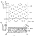
- Figs. 3 and 4 illustrate the main elements of a cathodic protection system for reinforced concrete structure, following the present invention.
- Fig. 3 is a plan view of a cathodically protected bridge slab, showing the anode net structure;
- fig. 4 is a sectional view along the line IV-IV of fig. 3.
- the slab consists in a metallic reinforcement 10, behaving as cathode, buried in concrete 20, above which an anode net structure is laid.
- the anode net 30 is covered by a layer of cement 40, over which the asphalt 50 is then laid.
- the necessary potential difference between anode and cathode 10 is maintained by means of a feeder 60 able to operate at both constant voltage and constant current.
- At least one reference electrode 70 is installed, connected to a control unit 80, that intervenes on the feeder 60 for necessary adjustments, in order to keep the system in proper protection conditions, avoiding any overprotection risks.
Landscapes
- Chemical & Material Sciences (AREA)
- Engineering & Computer Science (AREA)
- Materials Engineering (AREA)
- Mechanical Engineering (AREA)
- Metallurgy (AREA)
- Organic Chemistry (AREA)
- Prevention Of Electric Corrosion (AREA)
- Control Of Non-Electrical Variables (AREA)
Abstract
Description
- The present invention finds its application in the field of impressed current cathodic protection of reinforced concrete structures.
- Cathodic protection of reinforced concrete is used to prevent or to stop corrosion of metallic reinforcements.
- The most typical application field is in bridges, slabs, beams, piers, multi-store parkings garages, etc, - situated in cold regions, where corrosion is caused by de-icing salts, as well as in structures exposed to marine environment.
- This kind of systems is realized either using an anode structure typically having a net arrangement (i.e. titanium activated by noble metal oxides) or applying conductive coatings.
- The main characteristic of any cathodic protection system in reinforced concrete structures is to guarantee that the protection conditions be extended to the whole surface of reinforcements, without reaching over-protection conditions.
- The former condition obviously applies to any kind of structures; the latter, though being important in the protection of standard reinforced concrete structures, becomes mandatory where pre-stressed or post-tensioned concrete elements are present and have to be protected. In fact, steels used for this type of structures exibit very high mechanical characteristics, generally not lower than 1400 MPa, making them extremely exposed to the risk of hydrogen embrittlement phenomena.
- This means that, in a cathodic protection system applied to a pre-stressed or post-tensioned reinforced concrete structure, if the potential of these steels gets below the threshold value, in correspondence of which the hydrogen evolution reaction becomes appreciable, hydrogen embrittlement may occur.
- For the steels generally used in these structures, this threshold value ranges around -0.9 V with respect to Ag/AgCl electrode (W.H.Hartt, P.K.Narayanan, T.Y.Chen, C.C.Kumira, "Cathodic Protection and Environmental Cracking of Prestressing Steel", CORROSION/89, paper n. 382, NACE, New Orleans, Aprile 1989; R.N.Parkins et al., "Environmental Sensitive Cracking of Prestressing Steels", Corrosion Science 22, p. 379, 1982).
- When using carbon or low alloy steels showing ordinary mechanical characteristics, no embrittlement is observed. A threshold value is however set around - 1.1 V (The Concrete Society Tech. Report N, 36 "Cathodic Protection of Reinforced Concrete", London 1988). In fact, beyond this potential value, it is not advisable to operate, not only due to economic reasons, but also to avoid possible occurrence of reduced bond between concrete and reinforcement.
- Traditional monitoring technique for cathodic protection is based on the following check operations:
- 1. protection conditions are reached (i.e. by means of the so-called 100 mV decay method, that consists in checking that the cathodic potential variation, in the first four hours after opening the circuit, exceeds 100 mV) and,
- 2. potential of reinforcements is always nobler than the above mentioned critical value so as to exclude any over-protection risks.
- That criteria are not suitable for pre-stressed concrete and, in any case, also for ordinary concrete, cannot avoid overprotection condition in some points (for instance, where rebars are very close to the anode, in correspondence of zone of concrete where the resistivity becomes unexpectedly very low due to chloride contamination). In fact, the detection of possible over-protection conditions is strongly dependent on the location of reference electrodes (portable or fixed); it follows that only monitored zones (i.e. presence of reference electrode) are controlled, that means a few percent of the protected area, and are not representative of the map of the potentials on the whole surface of reinforcements. In effect, the potential of the surface of reinforcements is not uniform, but varies from one to another point, depending on the position with respect to the anode surface and to surrounding reinforcements. The amount of the variations changes with operating and environmental conditions. For instance, during winter or in high atmospheric humidity conditions, for which the oxygen diffusion within concrete results difficult, such local variations may be very high.
- The present invention consists in a device able to check that protection conditions are reached (i.e. using the well-known 100 mV decay method) and to ensure that no over-protection conditions are achieved.
- The innovative idea has its base on the measurement of the potential of the anode, instead of the measurement of the potential of the protected structure (i.e. reinforcements) as it has been done up to now for the concrete cathodic protection applications.
- Moreover the present invention is based on some peculiar features regarding voltages involved in cathodic protection systems for concrete.
- The feeding voltage, E, can be considered as the sum of: anode voltage, Ea, cathodic voltage Ec, ohmic drops in metallic conductors, Em, and ohmic drops in concrete, Eohm:

As far as Ec is concerned, it should be ranged within an interval limited, on its lower side, by the above mentioned minimum value, that is in case of high strength steels, for pre-stressed or post-stressed reinforced concrete -0.90 V, whereas for standard steels used in reinforced concrete -1.1 V (all potential values are referred to Ag/AgCl electrode). - As far as Ea is concerned, it slowly rises in time, at least in the first years operation. In case of activated titanium, it passes, from an initial value of about 0.4 V to 0.7-0.9 V, or higher, a few years after (P. Pedeferri et al. "Cathodic protection of Steel in Concrete with Expanded Titanium Anode Net System", UK Corrosion Conference, Blackpool, England, 8-10 November). It can also vary with environmental conditions, particularly with temperature and therefore with seasons. However, unlike cathodic potential, Ea is generally uniform on all the anode surface. This uniformity depends on the use of the special distributors that reduce attenuation as well as on the particular electrocatalytic characteristics of the materials used.
- The ohmic drop Eohm has very low values, because of the low currents involved, except for in particularly dry concrete. It is mainly localized in close proximity of the anode, where current density is greater. The term of any ohmic drop different from the ohmic drop in proximity of the anode can therefore be disregarded (and this makes the whole system more conservative). The ohmic contribution localized on the anode is determined along with the anode potential by means of reference electrode placed between anode and cathode (i.e. the same electrode used to check that protection conditions are reached by means of 100 mV decay method can be utilized). Actually, the meaning of anode potential here considered, Ea,on results to be equal to Ea true + Eohm (see equation 1).
- The term Em ohmic drop in metallic conductors, includes ohmic drops in the anodic feeding cables (ohmic drops in the rebars are negligible) and ohmic drops in anodic structures, i.e. the net and the relevant distribution strips. It depends on the flowing current.
- Therefore equation (1) can be rewritten as follows:

The present invention consists in a device for the control and regulation of the feeding unit in cathodic protection systems for reinforced concrete, that is based on the measurement of the feed voltage and of the anode potential instead of the cathodic potential, as it happens in traditional cathodic protection systems. - This device is able to guarantee safe protection conditions of reinforcements, as far as overprotection is concerned.
- This device, in its preferred embodiment, consists of a control unit where the following parameters are set: minimum protection potential (-0.90 or -1.1 V); initial voltage or current, Eo or Io; this control unit periodically determines: feed voltage, E, and anode potential Ea,on; the current involved and the ohmic drop contribution in metallic conductors, Em; moreover, it performs routine protection tests based, for instance, on 100 mV decay method.
- The control unit can be applied to systems operating both at "imposed voltage" (called "constant voltage") and at "imposed current" (called "constant current").
- If system operates at "constant voltage", the control unit imposes the pre-established initial voltage, checks, based on one or more measurements of the cathodic potential and following traditional principle, that protection conditions of reinforcements be reached (i.e. using the well-known 100 mV decay criteria) and, if such conditions would not be reached, it adjusts the feed voltage in order to meet this requirement; then, it measures the anode potential, Ea,on, then it calculates the cathodic potential Ec in order to check that no overprotection conditions are achieved.
- In case of pre-stressed concrete structures, it checks that the following inequality is verified:

In case of standard reinforced concrete structures:

The measurement of the anode potential Ea is therefore periodically performed, for example a few times every day, always re-calculating the operating voltage of the feeder. - A more accurate control can be realized if the anodic potential is taken as close as possible to the electrical connection of the power cables to the anodic structure, by means of an auxiliary, current free, electrical cable. In this case, in fact, the contribution of the ohmic drop in the cables is eliminated.
- In case of feeding "at constant current", the control unit imposes a pre-established initial current and checks that protection conditions be reached without the occurrence of overprotection conditions. This latter control is carried out by means of a measurement of the feed voltage and the anode potential and of the calculation of the cathodic potential as per equation (2), that should be greater than the above-cited threshold values. If this threshold value results to exceed the cathodic potential, the control unit reduces the feed current so as to exclude overprotection conditions.
- In a simplified version of the device, the feeding unit imposes a constant voltage, E, calculated as the sum of the measured anode potential Ea,on of the cathodic potential Ec and of the ohmic contributions, Em, where Ec and Em contributions are pre-determined; the control and automatic regulation are performed by periodically measuring the potential of the anode structure Ea,on, and then re-calculating the new feed voltage, so as to keep the structure constantly under protection conditions, avoiding any overprotection risks.
- The anode potential Ea,on can be measured using several reference electrodes which are representative of zones with different concrete conductivity, when using such several electrodes, the control device should be able to properly process signals so as to obtain one value (i.e. the lowest value) to be entered in the sum for E calculation.
- As above discussed, the principle of the system relies mainly on the higher uniformity of the potential of the anodic structure, compared with the cathode.
- On this regard, possible reasons for a non uniform potential of the anode are:
- a. - ohmic drops (or attenuation) in the metallic conductors (anode net included)
- b. - non uniform current requirements on the structures
- With reference to the second aspect, that is non-uniform current distribution all over the structure, it is often difficult to predict areas of higher current density. However relevant mistakes are limited because of the specific electrochemical behaviour of the anodic material has considered. In fact, as it results from readings taken on a real structure under protection, when the current density increases from 10 to 20 ma/m² (concrete surface), the anodic potential goes from +0.47 V vs Ag/AgCl to +530, which means a potential disuniformity lower than 60 mV.
- As a protection against possible failures that might take place in the circuits or in reference electrodes, the device is provided with a safety system which, when the feed voltage should reach a given Emax value, automatically brings the voltage back to a lower value Emin (i.e. 1.5 V), pre-established as well, simultaneously activating an alarm signal. In this way, the cathodic protection system could operate in under protection conditions, but it would never find in the much more dangerous over-protection conditions.
- Furthermore, in case the control device couldn't regulate the power unit, another protection can be foreseen which automatically switch off the transformer rectifier.
- The device is realized as an "intelligent" system, such as for instance a microprocessor or a personal computer, equipped with an adequate number of analogical inputs and outputs, able to run a program for the management of the system and of variables: input data acquisition, measurement of the anode potential, calculation of the feed voltage etc: The system is then connected to the feeding unit, to which it transmits the order for the adjustment of the voltage or feeding current, and if necessary, to a data acquisition unit for storing all systems current data or to a data transmission unit.
- A system for cathodic protection of a pre-stressed concrete bridge deck consists of several units, each one with its own transformer-rectifier feeding a mixed metal oxide activated titaniun net, having a rectangular surface of 360 m².
- Connections between power cables and anodic structure are located at one side of the net.
- A reference electrode has been placed in correspondance of the power connection side, positioned close to the titanium net. A second reference electrode of the same type has been placed at the opposite side, close to the rebar.
- The anodic structure has been designed to have a maximum ohmic drop in metallic conductors lower than 100 mV at the maximum design current density, equal to 20 mA/m² referred to the concrete surface.
- Free corrosion potential of rebar, measured by means of fixed reference electrodes as well as by portable ones, ranges between -0.1 and -0.25 V vs Ag/AgCl, while the potential of the anodic structures in same conditions is equal to -0.18 V.
- Power unit is a "constant voltage" type and it is controlled by an automatic regulation device which operates as follows. The control unit informs the power unit to start with an initial voltage E0 equal to 1.0 V, calculated by the operator assuming Ec = - 0.5 V, Ea,on = 0.45 V and Em = 0.05 V. Current output is equal to 3.2 A, corresponding to a current density of 9 mA/m². The control unit checks that protection conditions are reached, in accordance with the 100 mV decay criteria, and it takes the reading of Ea,on. Then it verifies that the following inequality is verified:

where -0.90 V represents the more negative allowed potential for the cathode, i.e. the rebar. - At start up, with 1.0 V applied, protection conditions are satisfied (about 150 mV of polarization are measured in the off status), and the measured potential of the anode, Ea,on, is equal to + 0.43 V. From these figures, assuming as stated above 50 mV as maximum allowed contribution for ohmic drops, the calculated value for Ec is equal to -0.52 V, more positive than the minimum allowed.
- After almost two years the anodic potential increased to +0.75 V and in the mean time polarization of the rebar falls below 100 mV. In accordance to these data, the control unit automatically increased the applied potential from 1.0 to 1.2 V, step by step, recalculating the cathode potential, Ec, equal to -0.45 V, and verifying the compliance with above written inequality, which again is verified.
- If this would not be achieved, the device reduces the applied voltage and repeats control operations.
- Fig. 1 reports the flux diagram of the operation carried out by the control unit.
- Reinforced concrete slab protected using a "constant current" feeding system. No high strength steel is present. The system imposes an initial current density of 10 mA/m² (based on experience, the initial current required is ranged between 10 and 20 mA/m²) and calculates circulating current and ohmic drops in wires. The system adjusts current so that the protection conditions are reached, based in 100 mV decay method; in the negative, it adjusts current until reaching protection conditions.
- At the same time, it measures E0 and Ea, on and verified the inequality

If this would not be achieved, it reduces current by 20% and repeats the control. - Fig. 2 reports the diagram of the device.
- Figs. 3 and 4 illustrate the main elements of a cathodic protection system for reinforced concrete structure, following the present invention.
- Fig. 3 is a plan view of a cathodically protected bridge slab, showing the anode net structure; fig. 4 is a sectional view along the line IV-IV of fig. 3.
- The slab consists in a metallic reinforcement 10, behaving as cathode, buried in concrete 20, above which an anode net structure is laid. The anode net 30 is covered by a layer of cement 40, over which the asphalt 50 is then laid.
- The necessary potential difference between anode and cathode 10 is maintained by means of a feeder 60 able to operate at both constant voltage and constant current.
- Between anode 30 and cathode 10, at least one
reference electrode 70 is installed, connected to a control unit 80, that intervenes on the feeder 60 for necessary adjustments, in order to keep the system in proper protection conditions, avoiding any overprotection risks.
Claims (10)
- Device for control and automatic regulation of the feeding unit (60) of impressed current cathodic protection systems in a reinforced concrete structure, including a metallic reinforcement (10) behaving as cathode to which an anode structure (30) is associated, characterized in that said device is able to measure the feed voltage E, which can be considered as the sum of anode voltage Ea, cathodic voltage Ec, ohmic drops in metallic conductors, Em, and ohmic drops in concrete, Eohm :


- Device as claimed in claim 1, where said feeding unit (60) operates at constant voltage or at constant current.
- Device as claimed in claim 1, where said reference electrode (70) is buried in the reinforced concrete structure and is placed between the cathodic and the anodic structure.
- Device as claimed in claim 1, where the anode structure is a net structure, buried in reinforced concrete.
- Device as claimed in any of the previous claims, where the control device (80) is connected to several reference electrodes (70) and is able to properly process signals, for instance to calculate the mean, root-mean-square deviation, to select a part of measurement, to assess the reliability of measurements.
- Device as claimed in any of the previous claims, characterized in that when the feed voltage or current reaches a pre-established threshold value, the control device (80) automatically activates an alarm signal, and brings the voltage or current back to a pre-established minimum value.
- Device as claimed in any of the previous claims, comprising a memory unit onto which the device (80) periodically transfers all systems operating parameters.
- Device as claimed in any of the previous claims, where the control and regulation device (80) consists of an "intelligent system" such as a microprocessor or a personal computer provided with an adequate number of inputs and outputs, able to run a program of data management and processing, to acquire one or more voltage measurements by means of the reference electrodes (70) connected, and to supply the feeder (10) of the cathodic protection system with operating parameters, duly processed.
- Impressed current protection system, comprising a feeding unit (60), able to generate a potential difference between the cathodic reinforcement (10) and an anode structure (30) of a reinforced concrete structure, said system being characterized by a device (80) for the control and regulation of the feeding unit (60), as claimed in any of the claims from 1 to 8, in order to assure adequate protection of the cathodic structure (10), without any overprotection risks.
- Procedure for the control and automatic regulation of feeding of impressed current cathodic protection systems in reinforced concrete structures, performed with the device of claim 1, comprising an indirect measurement of the cathodic potential, based on which necessary adjustments can be made on the feeding in order to assure adequate protection of the metallic structure, while preventing any overprotection risks, said indirect measurement of the cathodic potential being made as the difference among the feed voltage E, the measured anode potential Ea,on and ohmic drops in metal conductors Em, using one or more reference electrodes (70).
Applications Claiming Priority (2)
| Application Number | Priority Date | Filing Date | Title |
|---|---|---|---|
| IT1948490 | 1990-02-26 | ||
| IT19484A IT1239344B (en) | 1990-02-26 | 1990-02-26 | AUTOMATIC CONTROL AND REGULATION DEVICE OF CATHODIC PROTECTION SYSTEMS OF REINFORCED CONCRETE STRUCTURES |
Publications (2)
| Publication Number | Publication Date |
|---|---|
| EP0448963A1 EP0448963A1 (en) | 1991-10-02 |
| EP0448963B1 true EP0448963B1 (en) | 1995-05-03 |
Family
ID=11158418
Family Applications (1)
| Application Number | Title | Priority Date | Filing Date |
|---|---|---|---|
| EP91102707A Expired - Lifetime EP0448963B1 (en) | 1990-02-26 | 1991-02-25 | Control and automatic regulation device for cathodic protection systems in reinforced concrete structures |
Country Status (6)
| Country | Link |
|---|---|
| US (1) | US5225058A (en) |
| EP (1) | EP0448963B1 (en) |
| AT (1) | ATE122105T1 (en) |
| CA (1) | CA2036863C (en) |
| DE (1) | DE69109356T2 (en) |
| IT (1) | IT1239344B (en) |
Families Citing this family (17)
| Publication number | Priority date | Publication date | Assignee | Title |
|---|---|---|---|---|
| JP3040613B2 (en) * | 1992-10-07 | 2000-05-15 | 大日本塗料株式会社 | Corrosion protection method for reinforced concrete structures |
| US5366670A (en) * | 1993-05-20 | 1994-11-22 | Giner, Inc. | Method of imparting corrosion resistance to reinforcing steel in concrete structures |
| US5532025A (en) * | 1993-07-23 | 1996-07-02 | Kinlen; Patrick J. | Corrosion inhibiting compositions |
| US5650060A (en) * | 1994-01-28 | 1997-07-22 | Minnesota Mining And Manufacturing Company | Ionically conductive agent, system for cathodic protection of galvanically active metals, and method and apparatus for using same |
| US6690182B2 (en) * | 2000-07-19 | 2004-02-10 | Virginia Technologies, Inc | Embeddable corrosion monitoring-instrument for steel reinforced structures |
| US6387244B1 (en) * | 2000-10-18 | 2002-05-14 | Cor/Sci, Llc. | Cathodic protection of reinforced concrete with impregnated corrosion inhibitor |
| US6419816B1 (en) * | 2000-10-18 | 2002-07-16 | Cor/Sci, Llc. | Cathodic protection of steel in reinforced concrete with electroosmotic treatment |
| US7064459B1 (en) * | 2001-08-20 | 2006-06-20 | Brunswick Corporation | Method of inhibiting corrosion of a component of a marine vessel |
| EP1777322A1 (en) * | 2005-10-18 | 2007-04-25 | Technische Universiteit Delft | Apparatus for cathodic protection of steel reinforced concrete structures and method |
| CN101738368B (en) * | 2008-11-18 | 2012-10-03 | 北京市水利规划设计研究院 | Concrete pipe cathode protection testing probe and testing method |
| GB2474084A (en) * | 2009-10-13 | 2011-04-06 | Aish Technologies Ltd | Impressed current cathodic protection (ICCP) |
| KR101347707B1 (en) * | 2011-10-28 | 2014-01-06 | 주식회사 화승알앤에이 | Hybrid type cathode protection system sacrificial anode type cathode protection technologies for marine concrete structure |
| WO2013152398A1 (en) * | 2012-04-11 | 2013-10-17 | Anode Engineering Pty Ltd | Cathodic protection system |
| US9353446B2 (en) | 2013-04-29 | 2016-05-31 | Transistor Devices, Inc. | Systems and methods for impressed current cathodic protection |
| CN104005032B (en) * | 2014-05-08 | 2016-08-24 | 青岛双瑞海洋环境工程股份有限公司 | The cathode protection testing probe in Prestressed concrete cylinder pipe road and preparation method |
| US11261530B2 (en) * | 2019-03-11 | 2022-03-01 | Prorbar, Inc. | Cathodic protection system and miniaturized constant current rectifier |
| CN114703480B (en) * | 2022-04-15 | 2024-03-22 | 青岛雅合科技发展有限公司 | Regional cathodic protection control method |
Family Cites Families (8)
| Publication number | Priority date | Publication date | Assignee | Title |
|---|---|---|---|---|
| US3208925A (en) * | 1960-01-07 | 1965-09-28 | Continental Oil Co | Anodic protection against corrosion |
| NL275599A (en) * | 1961-03-07 | |||
| US3714004A (en) * | 1970-12-02 | 1973-01-30 | Continental Oil Co | Method and apparatus for cathodic protection |
| US4255241A (en) * | 1979-05-10 | 1981-03-10 | Kroon David H | Cathodic protection apparatus and method for steel reinforced concrete structures |
| GB2140456A (en) * | 1982-12-02 | 1984-11-28 | Taywood Engineering Limited | Cathodic protection |
| US4592818A (en) * | 1983-09-12 | 1986-06-03 | Outboard Marine Corporation | Cathodic protection system |
| DE3419612C2 (en) * | 1984-05-25 | 1986-06-12 | Felten & Guilleaume Energietechnik GmbH, 5000 Köln | Method and device for monitoring cathodic corrosion protection |
| US4855024A (en) * | 1986-09-16 | 1989-08-08 | Raychem Corporation | Mesh electrodes and clips for use in preparing them |
-
1990
- 1990-02-26 IT IT19484A patent/IT1239344B/en active IP Right Grant
-
1991
- 1991-02-22 US US07/659,269 patent/US5225058A/en not_active Expired - Fee Related
- 1991-02-25 EP EP91102707A patent/EP0448963B1/en not_active Expired - Lifetime
- 1991-02-25 AT AT91102707T patent/ATE122105T1/en not_active IP Right Cessation
- 1991-02-25 DE DE69109356T patent/DE69109356T2/en not_active Expired - Fee Related
- 1991-02-25 CA CA002036863A patent/CA2036863C/en not_active Expired - Fee Related
Also Published As
| Publication number | Publication date |
|---|---|
| CA2036863C (en) | 2001-01-23 |
| IT9019484A0 (en) | 1990-02-26 |
| US5225058A (en) | 1993-07-06 |
| CA2036863A1 (en) | 1991-08-27 |
| EP0448963A1 (en) | 1991-10-02 |
| IT9019484A1 (en) | 1991-08-26 |
| ATE122105T1 (en) | 1995-05-15 |
| DE69109356D1 (en) | 1995-06-08 |
| DE69109356T2 (en) | 1996-01-11 |
| IT1239344B (en) | 1993-10-20 |
Similar Documents
| Publication | Publication Date | Title |
|---|---|---|
| EP0448963B1 (en) | Control and automatic regulation device for cathodic protection systems in reinforced concrete structures | |
| Feliu et al. | On-site determination of the polarization resistance in a reinforced concrete beam | |
| CA1141699A (en) | Cathodic protection including wires in carbonaceous matrix for steel-concrete structures | |
| Bertolini et al. | Cathodic protection and cathodic preventionin concrete: principles and applications | |
| Elsener | Macrocell corrosion of steel in concrete–implications for corrosion monitoring | |
| US20030169058A1 (en) | System to measure the state of corrosion of buried metallic structures continuously in time and in length | |
| Feliu et al. | Multiple-electrode method for estimating the polarization resistance in large structures | |
| Gowers et al. | Programmable linear polarisation meter for determination of corrosion rate of reinforcement in concrete structures | |
| Sagues et al. | Corrosion performance of epoxy-coated reinforcing steel in marine substructure service | |
| EP0593168B1 (en) | Method and apparatus for measuring underdeposit localized corrosion rate or metal corrosion rate under tubercles in cooling water systems | |
| Bennett et al. | Cathodic protection of concrete bridges: a manual of practice | |
| Evitts et al. | Cathodic protection | |
| US6582587B1 (en) | Cathodic protection design method, current mapping and system | |
| Schiegg et al. | On-line monitoring of corrosion in reinforced concrete structures | |
| Bennett et al. | Technical alert: criteria for the cathodic protection of reinforced concrete bridge elements | |
| Srinivasan et al. | Design of cathodic protection of rebars in concrete structures: An electrochemical engineering approach | |
| Qian et al. | Evaluation of Reinforcement Corrosion in Repaired Concrete Bridge SlabsA Case Study | |
| Millard | CORROSION RATE MEASUREMENT OF IN-SITU REINFORCED CONCRETE STRUCTURES. | |
| Bazzoni et al. | Field application of cathodic prevention on reinforced concrete structures | |
| Sagüés et al. | An approach for the evaluation of performance of point anodes for corrosion prevention of reinforcing steel in concrete repairs | |
| Cheaitani | Cathodic Protection to the Port of Brisbane Structure, Australia | |
| Broomfield | Monitoring cathodic protection in concrete and masonry structures | |
| RU2419090C2 (en) | Method and sensor for determining passivating properties of mixture containing cement and water | |
| Giorgini et al. | Assessment of the throwing power generated by a surface applied galvanic cathodic protection system on a light weight concrete bridge deck soffit | |
| Van Belleghem et al. | Impressed current cathodic protection of reinforced concrete in ATEX-zones–Case study: concrete slab in an industrial building |
Legal Events
| Date | Code | Title | Description |
|---|---|---|---|
| PUAI | Public reference made under article 153(3) epc to a published international application that has entered the european phase |
Free format text: ORIGINAL CODE: 0009012 |
|
| AK | Designated contracting states |
Kind code of ref document: A1 Designated state(s): AT BE CH DE DK ES FR GB GR IT LI LU NL SE |
|
| 17P | Request for examination filed |
Effective date: 19920311 |
|
| 17Q | First examination report despatched |
Effective date: 19940204 |
|
| GRAA | (expected) grant |
Free format text: ORIGINAL CODE: 0009210 |
|
| AK | Designated contracting states |
Kind code of ref document: B1 Designated state(s): AT BE CH DE DK ES FR GB GR IT LI LU NL SE |
|
| PG25 | Lapsed in a contracting state [announced via postgrant information from national office to epo] |
Ref country code: NL Free format text: LAPSE BECAUSE OF FAILURE TO SUBMIT A TRANSLATION OF THE DESCRIPTION OR TO PAY THE FEE WITHIN THE PRESCRIBED TIME-LIMIT Effective date: 19950503 Ref country code: GR Free format text: LAPSE BECAUSE OF FAILURE TO SUBMIT A TRANSLATION OF THE DESCRIPTION OR TO PAY THE FEE WITHIN THE PRESCRIBED TIME-LIMIT Effective date: 19950503 Ref country code: FR Effective date: 19950503 Ref country code: ES Free format text: THE PATENT HAS BEEN ANNULLED BY A DECISION OF A NATIONAL AUTHORITY Effective date: 19950503 Ref country code: DK Effective date: 19950503 Ref country code: BE Effective date: 19950503 Ref country code: AT Effective date: 19950503 |
|
| REF | Corresponds to: |
Ref document number: 122105 Country of ref document: AT Date of ref document: 19950515 Kind code of ref document: T |
|
| ITF | It: translation for a ep patent filed |
Owner name: STUDIO CONS. BREVETTUALE S.R.L. |
|
| REF | Corresponds to: |
Ref document number: 69109356 Country of ref document: DE Date of ref document: 19950608 |
|
| PG25 | Lapsed in a contracting state [announced via postgrant information from national office to epo] |
Ref country code: SE Effective date: 19950803 |
|
| EN | Fr: translation not filed | ||
| NLV1 | Nl: lapsed or annulled due to failure to fulfill the requirements of art. 29p and 29m of the patents act | ||
| PG25 | Lapsed in a contracting state [announced via postgrant information from national office to epo] |
Ref country code: LU Free format text: LAPSE BECAUSE OF NON-PAYMENT OF DUE FEES Effective date: 19960229 |
|
| PLBE | No opposition filed within time limit |
Free format text: ORIGINAL CODE: 0009261 |
|
| STAA | Information on the status of an ep patent application or granted ep patent |
Free format text: STATUS: NO OPPOSITION FILED WITHIN TIME LIMIT |
|
| 26N | No opposition filed | ||
| REG | Reference to a national code |
Ref country code: CH Ref legal event code: PUE Owner name: NUOVA POLMET CATHODIC PROTECTION S.R.L. TRANSFER- |
|
| PGFP | Annual fee paid to national office [announced via postgrant information from national office to epo] |
Ref country code: GB Payment date: 20000222 Year of fee payment: 10 |
|
| PG25 | Lapsed in a contracting state [announced via postgrant information from national office to epo] |
Ref country code: GB Free format text: LAPSE BECAUSE OF NON-PAYMENT OF DUE FEES Effective date: 20010225 |
|
| GBPC | Gb: european patent ceased through non-payment of renewal fee |
Effective date: 20010225 |
|
| PGFP | Annual fee paid to national office [announced via postgrant information from national office to epo] |
Ref country code: CH Payment date: 20040217 Year of fee payment: 14 |
|
| PGFP | Annual fee paid to national office [announced via postgrant information from national office to epo] |
Ref country code: DE Payment date: 20040407 Year of fee payment: 14 |
|
| PG25 | Lapsed in a contracting state [announced via postgrant information from national office to epo] |
Ref country code: IT Free format text: LAPSE BECAUSE OF NON-PAYMENT OF DUE FEES;WARNING: LAPSES OF ITALIAN PATENTS WITH EFFECTIVE DATE BEFORE 2007 MAY HAVE OCCURRED AT ANY TIME BEFORE 2007. THE CORRECT EFFECTIVE DATE MAY BE DIFFERENT FROM THE ONE RECORDED. Effective date: 20050225 |
|
| PG25 | Lapsed in a contracting state [announced via postgrant information from national office to epo] |
Ref country code: LI Free format text: LAPSE BECAUSE OF NON-PAYMENT OF DUE FEES Effective date: 20050228 Ref country code: CH Free format text: LAPSE BECAUSE OF NON-PAYMENT OF DUE FEES Effective date: 20050228 |
|
| PG25 | Lapsed in a contracting state [announced via postgrant information from national office to epo] |
Ref country code: DE Free format text: LAPSE BECAUSE OF NON-PAYMENT OF DUE FEES Effective date: 20050901 |
|
| REG | Reference to a national code |
Ref country code: CH Ref legal event code: PL |