EP0448818A2 - Dispositif d'essai à rayonnement X, en particulier pour pneus - Google Patents
Dispositif d'essai à rayonnement X, en particulier pour pneus Download PDFInfo
- Publication number
- EP0448818A2 EP0448818A2 EP90124705A EP90124705A EP0448818A2 EP 0448818 A2 EP0448818 A2 EP 0448818A2 EP 90124705 A EP90124705 A EP 90124705A EP 90124705 A EP90124705 A EP 90124705A EP 0448818 A2 EP0448818 A2 EP 0448818A2
- Authority
- EP
- European Patent Office
- Prior art keywords
- diodes
- passage slot
- diode
- scanning
- tire
- Prior art date
- Legal status (The legal status is an assumption and is not a legal conclusion. Google has not performed a legal analysis and makes no representation as to the accuracy of the status listed.)
- Withdrawn
Links
Images


Classifications
-
- G—PHYSICS
- G01—MEASURING; TESTING
- G01M—TESTING STATIC OR DYNAMIC BALANCE OF MACHINES OR STRUCTURES; TESTING OF STRUCTURES OR APPARATUS, NOT OTHERWISE PROVIDED FOR
- G01M17/00—Testing of vehicles
- G01M17/007—Wheeled or endless-tracked vehicles
- G01M17/02—Tyres
- G01M17/028—Tyres using X-rays
-
- G—PHYSICS
- G01—MEASURING; TESTING
- G01N—INVESTIGATING OR ANALYSING MATERIALS BY DETERMINING THEIR CHEMICAL OR PHYSICAL PROPERTIES
- G01N23/00—Investigating or analysing materials by the use of wave or particle radiation, e.g. X-rays or neutrons, not covered by groups G01N3/00 – G01N17/00, G01N21/00 or G01N22/00
- G01N23/02—Investigating or analysing materials by the use of wave or particle radiation, e.g. X-rays or neutrons, not covered by groups G01N3/00 – G01N17/00, G01N21/00 or G01N22/00 by transmitting the radiation through the material
- G01N23/06—Investigating or analysing materials by the use of wave or particle radiation, e.g. X-rays or neutrons, not covered by groups G01N3/00 – G01N17/00, G01N21/00 or G01N22/00 by transmitting the radiation through the material and measuring the absorption
- G01N23/083—Investigating or analysing materials by the use of wave or particle radiation, e.g. X-rays or neutrons, not covered by groups G01N3/00 – G01N17/00, G01N21/00 or G01N22/00 by transmitting the radiation through the material and measuring the absorption the radiation being X-rays
-
- G—PHYSICS
- G01—MEASURING; TESTING
- G01N—INVESTIGATING OR ANALYSING MATERIALS BY DETERMINING THEIR CHEMICAL OR PHYSICAL PROPERTIES
- G01N23/00—Investigating or analysing materials by the use of wave or particle radiation, e.g. X-rays or neutrons, not covered by groups G01N3/00 – G01N17/00, G01N21/00 or G01N22/00
- G01N23/02—Investigating or analysing materials by the use of wave or particle radiation, e.g. X-rays or neutrons, not covered by groups G01N3/00 – G01N17/00, G01N21/00 or G01N22/00 by transmitting the radiation through the material
- G01N23/06—Investigating or analysing materials by the use of wave or particle radiation, e.g. X-rays or neutrons, not covered by groups G01N3/00 – G01N17/00, G01N21/00 or G01N22/00 by transmitting the radiation through the material and measuring the absorption
- G01N23/16—Investigating or analysing materials by the use of wave or particle radiation, e.g. X-rays or neutrons, not covered by groups G01N3/00 – G01N17/00, G01N21/00 or G01N22/00 by transmitting the radiation through the material and measuring the absorption the material being a moving sheet or film
-
- G—PHYSICS
- G01—MEASURING; TESTING
- G01N—INVESTIGATING OR ANALYSING MATERIALS BY DETERMINING THEIR CHEMICAL OR PHYSICAL PROPERTIES
- G01N23/00—Investigating or analysing materials by the use of wave or particle radiation, e.g. X-rays or neutrons, not covered by groups G01N3/00 – G01N17/00, G01N21/00 or G01N22/00
- G01N23/02—Investigating or analysing materials by the use of wave or particle radiation, e.g. X-rays or neutrons, not covered by groups G01N3/00 – G01N17/00, G01N21/00 or G01N22/00 by transmitting the radiation through the material
- G01N23/06—Investigating or analysing materials by the use of wave or particle radiation, e.g. X-rays or neutrons, not covered by groups G01N3/00 – G01N17/00, G01N21/00 or G01N22/00 by transmitting the radiation through the material and measuring the absorption
- G01N23/18—Investigating the presence of flaws defects or foreign matter
- G01N23/185—Investigating the presence of flaws defects or foreign matter in tyres
-
- G—PHYSICS
- G01—MEASURING; TESTING
- G01N—INVESTIGATING OR ANALYSING MATERIALS BY DETERMINING THEIR CHEMICAL OR PHYSICAL PROPERTIES
- G01N2223/00—Investigating materials by wave or particle radiation
- G01N2223/60—Specific applications or type of materials
- G01N2223/627—Specific applications or type of materials tyres
Definitions
- the invention relates to a device for testing workpieces by means of X-rays, in particular motor vehicle tires according to the preamble of patent claim 1.
- Each diode arrangement has a linear row of light-sensitive diodes, for example with a pitch of 0.45 or even a pitch of 0.225 mm.
- the receiving area of the diodes is provided with a fluorescent layer.
- the light caused by the X-rays in the fluorescent layer is registered by the light-sensitive diodes and converted into an electrical signal.
- the diodes in the diode arrays are scanned serially by a scanner and the outputs of the diodes are placed on a memory.
- An image display device consisting of individual pixels is used to generate image lines per scanning sequence for a diode arrangement. A certain surface section of the tire section to be tested is therefore displayed on the screen of the diode arrangement.
- the known device enables an almost vertical irradiation of all areas to be checked and, not least because of this, enables a distortion-free display on the reproduction device.
- the distance between the diodes and the tires can be adjusted so that the same imaging scale can always be achieved even with tires of different sizes, which considerably facilitates the inspection of a tire by a control person. It is particularly advantageous that even with tire reinforcements made of plastic material (plastic cord) despite the low Contrast a screen display is possible.
- the light-sensitive diodes including their electronics, are housed in an airtight housing to protect the sensitive parts against environmental influences, in particular against dust.
- the housing requires a passage slot for the X-rays, this is also covered, however, by a radiation-permeable material in order to avoid absorption of the X-rays.
- the housing area is provided with a lead shield at least on both sides of the through-slot, which is intended to prevent X-rays passing through the housing wall from impairing or even destroying the circuit electronics for the diodes.
- the dimension of the housing in the known diode arrangement in the direction of the irradiation is relatively large, the diodes being arranged close to the wall of the housing opposite the passage slot.
- the width of the passage slot cannot be made arbitrarily small, since it must be ensured that the incoming radiation is incident in the plane of the row of diodes. Tolerances in the housing of the diode arrangement and in the rest of the test device therefore require one Minimum entry width in the passage slot.
- the X-ray radiation entering the housing over a greater width can cause scattered radiation in the housing, as a result of which the service life of the electronic components is also shortened.
- a very small division of the diodes of a row of diodes enables a high resolution to be achieved, so that reinforcements in tires made of plastic fibers, for example, can also be checked.
- Diode rows with a pitch of 0.2225 can already be produced.
- the extension of the receiving surface of such diodes across the line of the diodes is, however, considerably larger for technical reasons and is currently about 0.6 mm. If a tissue is now to be tested in which the threads also run approximately parallel to the diode line and the threads are at a distance which is smaller than the extension of the diodes across the diode row, it can happen that two threads are imaged simultaneously on the receiving surface. An electrical averaging occurs and perfect resolution can no longer be guaranteed.
- the X-ray examination e.g. of automobile tires is based on the fact that the tire base material and the inserts absorb the X-rays differently. Between the base material of the tire and e.g. Steel inserts can achieve a relatively clear contrast. It is also known to reinforce tires with textile inserts (plastic cord), especially the tire flanks. Such inserts have a lower density than rubber and produce a relatively poor contrast. Tires with both steel and textile inserts cannot therefore be checked at the same time. In order to obtain a satisfactory resolution with plastic cord, for example, the X-ray omnidirectional tube must be operated with a relatively low voltage. However, this tension is not sufficient to make the structure of steel inserts sufficiently visible. It is therefore necessary to set different tensions depending on which tire reinforcement is to be examined.
- a shield made of an X-ray absorbing material, for example lead is arranged within the housing near the row of diodes and forms a second through-slot aligned with the first through-slot and the row of diodes, the width of which is smaller than that of the first passage slot and smaller than the extension of the diodes across the diode row.
- the width of the second passage slot is at most half as large as the extent of the receiving area of the diodes transverse to the direction of the diode row.
- the first passage slot is dimensioned such that sufficient X-ray radiation enters the housing regardless of the tolerances that occur.
- the second shield consisting of the two lead strips or plates, forms a narrower slot, which ensures that only the receiving area of the diodes is irradiated by X-rays, but not the radiation-sensitive electronics located next to it.
- the advantage is obtained that the X-ray radiation strikes only a part of the receiving area of the diode. This enables a higher resolution to be obtained, the degree of resolution depending on the width of the slot. If, for example, a motor vehicle tire or a carcass strand for producing a motor vehicle tire is tested, in which threads also run parallel to the extent of the passage slot, these can be very close to one another and nevertheless be made clearly visible.
- the diodes of the diode arrangements are arranged at a distance which, in particular, makes textile inserts in the tire sufficiently high-resolution, making them sufficiently visible.
- the distance between the diodes, in particular the diode rows assigned to the tire flanks, is dimensioned such that, with a correspondingly selected voltage on the X-ray tube, a sufficient resolution with plastic cord is also achieved.
- the distance is, for example, less than 0.5 mm, preferably less than 0.3 mm or less. In adaptation to conventional image display devices, this means a number of 1024 diodes per diode line or 2048. In particular, the latter number of diodes per line is completely sufficient to achieve a satisfactory resolution with plastic filament inserts with the corresponding operating voltage of the X-ray omnidirectional tube.
- the duration of a sampling sequence depends on the number of diodes scanned per row of diodes.
- the advantage of a higher resolution is therefore bought with a longer test time. Since the proportion of tires with plastic cord is now low in relation to tires that only have steel inserts, a system that is able to test both tires with plastic cord and steel cord would have one cause a relatively long test duration per vehicle tire.
- the scanning device is optionally only scanned every second, third, etc. diode of a row of diodes.
- the device according to the invention is therefore designed with regard to the structure of the diode rows so that a satisfactory resolution is achieved for testing tires with plastic cord.
- the scanning device does not scan all the diodes of a row of diodes, but only every second, third, etc. This naturally reduces the scanning time by half, one third, etc.
- an optimal test time for the tires to be tested is therefore obtained depending on the properties of the reinforcing inserts.
- the scanning of the diode rows can also be carried out in blocks or in groups, in contrast to scanning in a linear sequence. When scanning with a lower resolution, only a part of the diodes of a group or a block is then scanned, ie predetermined diodes (eg even numbers in a row) are skipped during the scanning.
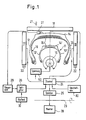
- the tire 10 and 11 is rotatably supported about its axis in a known manner. It is rotated with the aid of a rotating device (not shown) about its axis 23, which lies, for example, in a vertical plane, the peripheral speed being able to be specified and changed by the operator.
- a rotating device not shown
- the corresponding constructive arrangements for this are not shown; they are state of the art.
- the protective precautions customary in X-ray inspection devices are also not shown.
- an X-ray omnidirectional tube 16 is arranged at the entrance of the tires 10 and 11, respectively.
- the X-ray omnidirectional tube 16 In a radial plane for ripening (here in the drawing plane), the X-ray omnidirectional tube 16 has a radiation angle of approximately 300 °, for example. In the radial plane, therefore, all areas of the tire are irradiated by the radiation of the tube 16, to be precise approximately at a transmission angle of 90 °. It goes without saying that the position of the X-ray omnidirectional tube 16 can also be relocated, for example further into the tire or further outside. In a plane perpendicular to the radial plane, the tube 16 has a radiation angle of, for example, 40 °.
- Diode arrangements 17, 18, 19 are provided on the outside of the tire flanks 12, 13 or 12 ', 13' and on the outside of the tread 14 or 14 '. These are only indicated schematically in FIG. 1.
- Each diode arrangement 17 to 19 contains a linear arrangement of individual light-sensitive diodes, for example 2048 per diode arrangement at a distance of 0.225 mm, the receiving surface of which is provided with a fluorescent layer which generates a light usable for the diodes from the X-rays.
- the arrangement of the rows of diodes is approximately parallel to the diameter or parallel to the axis of the tires 10 or 11.
- the diodes are scanned periodically by a scanner 24, the scanned signals being stored in a known manner in the memory 25 such that a series of scans appears simultaneously on a display device 20, for example a screen.
- the reproduction device 20 is also indicated schematically. It consists of three separate screens (not shown).
- the scanning speed of the scanner is specified by a clock generator 26.
- a speed sensor 27, for example a speedometer roller, is assigned to the tread 14, 14 'of the tires 10, 11. Its output signal goes to a control device 29 which is connected to the clock generator 26.
- the scanning speed of the scanner 24 is varied in accordance with the speed of the tires 10, 11 in order to obtain an identical image scale with a predetermined distance of the diode arrangements 17 to 19 from the tire.
- the control device 29 calculates an average value for the tire speed of the flanks.
- the scanning for the tread 14, 14 'on the one hand and for the flanks 12, 12' on the other hand is therefore different. If the distance between the diode arrangements 17 to 19 changes with respect to the tire 10 or 11, the clock frequency must also be changed. This is indicated by block 30.
- the diode arrangements 17 to 19 can be adjusted relative to the tire 11, 12. This is not described in detail and is known, for example, from EP-A-0 315 099 mentioned at the outset.
- the voltage supply is indicated in the drawing by block 50.
- the voltage can be varied to create an optimal contrast.
- Plastic cord requires a "softer" tension than steel cord. The tension also depends on the thickness of the material to be tested.
- the block 50 can therefore also be connected to a device which receives signals from a thickness measuring device.
- the diodes of the diode arrangements 17 to 19 are arranged very close to one another, as already mentioned. Their distance is, for example, 0.225 mm. It is understood that the screen of the monitor 20 has a corresponding number of pixels per line.
- the scanning speed is relatively high, preferably 1 pixel per millisecond.
- a switch device 80 is assigned to the scanner 24.
- the switching device serves to change the number of diodes to be scanned per row of diodes.
- the scanner 24 can be set so that it scans only every second diode in a row of diodes of the diode arrays 17 to 19. It is understood that the resolution is only less with a scan of every second, third, etc. diode than with a scan of every diode; however, the poorer resolution is sufficient under certain circumstances with a correspondingly small diode spacing, for example to reliably detect steel inserts. If, on the other hand, it is necessary to check textile inserts, the switching device 80 causes all the diodes present in a row of diodes to be scanned cyclically.
- the diode arrangements 18 for the tread with a smaller number of diodes, for example 1024, which be sampled in each sequence. Only the diode arrangements 17 and 19 assigned to the tire flanks then each have 2048 diodes, the scanning arrangement of which depends on the nature of the material to be tested.
- a housing 100 can be seen in FIGS. 2 and 3, which comprises a relatively flat hood 110 and a counter the hood 110 is flanged plate 120.
- an elongated passage slot is formed on an end face at 140 (FIG. 3), which is covered by a radiation-transmissive cover (not shown further).
- a series of diodes 160 are arranged in the housing 100 near the end wall of the housing 100 which has the slot 140. For example, 1024 or 2048 diodes with a pitch of 0.45 or 0.225 mm are arranged in a row.
- connection 180 for the electrical supply of the diodes and the signal line to the diodes 160 and a connection to the electronics for the diodes 160 (not shown) arranged within the housing 100.
- FIG. 4 shows the front wall 200 having the passage slot 140 and the opposite rear wall 220.
- a lead shield 240 is applied to the front wall 200 and is flush with the passage slot 140.
- the passage slot formed as a result has a width of approximately 5 mm.
- the cover that normally slits slot 140 to prevent dust from entering is not shown.
- Circuit board 260 On the inside of the opposite wall 220 is one Circuit board 260 arranged, which carries electronics generally designated 280 for the diodes, one of which can be seen at 160a.
- Holders 300 and 310 made of aluminum are arranged near the electronics 280 and the diodes 160a, respectively, which hold narrow lead plates 320, 340, which form a slot 360 between them, the center of which is aligned with the center of the passage slot 140.
- the common axis of the slots 140, 360 is in turn aligned with the axis of the diode 160a.
- the holders 300, 310 are slightly behind the slot 360. This prevents stray radiation from being formed by the holders 300, 310, which would shorten the life of the electronics.
- the width X of the slot 360 is, for example, 0.2 to 0.4 mm. In any case, it is smaller than the extent of the receiving area of the diode 160a transverse to the longitudinal direction of the slot 360, which is, for example, 0.6 mm.
- the lead shielding formed by the strips or plates 320, 340 also ensures that the electronics 280 are not hit by X-rays in any case, but that the diodes 160a receive sufficient X-rays due to the sufficient width of the passage slot 140, regardless of the tolerant position of the whole Housing 100 opposite the radiation source or within the entire test device.
- the slot 360 can also be formed in a single plate by a suitable processing method, e.g. by means of laser processing.
Landscapes
- Health & Medical Sciences (AREA)
- Physics & Mathematics (AREA)
- General Physics & Mathematics (AREA)
- Life Sciences & Earth Sciences (AREA)
- Chemical & Material Sciences (AREA)
- Analytical Chemistry (AREA)
- Biochemistry (AREA)
- General Health & Medical Sciences (AREA)
- Immunology (AREA)
- Pathology (AREA)
- Toxicology (AREA)
- Analysing Materials By The Use Of Radiation (AREA)
Applications Claiming Priority (2)
| Application Number | Priority Date | Filing Date | Title |
|---|---|---|---|
| EP90102379 | 1990-02-06 | ||
| EP90102379A EP0440847B1 (fr) | 1990-02-06 | 1990-02-06 | Appareil pour l'examen aux rayons X d'un pneumatique de véhicule |
Publications (2)
| Publication Number | Publication Date |
|---|---|
| EP0448818A2 true EP0448818A2 (fr) | 1991-10-02 |
| EP0448818A3 EP0448818A3 (en) | 1992-06-24 |
Family
ID=8203603
Family Applications (2)
| Application Number | Title | Priority Date | Filing Date |
|---|---|---|---|
| EP90102379A Expired - Lifetime EP0440847B1 (fr) | 1990-02-06 | 1990-02-06 | Appareil pour l'examen aux rayons X d'un pneumatique de véhicule |
| EP19900124705 Withdrawn EP0448818A3 (en) | 1990-02-06 | 1990-12-19 | X-ray testing apparatus, in particular for vehicle tyres |
Family Applications Before (1)
| Application Number | Title | Priority Date | Filing Date |
|---|---|---|---|
| EP90102379A Expired - Lifetime EP0440847B1 (fr) | 1990-02-06 | 1990-02-06 | Appareil pour l'examen aux rayons X d'un pneumatique de véhicule |
Country Status (5)
| Country | Link |
|---|---|
| US (1) | US5148456A (fr) |
| EP (2) | EP0440847B1 (fr) |
| JP (1) | JPH05131816A (fr) |
| AT (1) | ATE105632T1 (fr) |
| DE (1) | DE59005684D1 (fr) |
Cited By (3)
| Publication number | Priority date | Publication date | Assignee | Title |
|---|---|---|---|---|
| FR2913770A1 (fr) * | 2007-03-15 | 2008-09-19 | Cybernetix Sa Sa | Detecteur de rayons x |
| WO2012065752A3 (fr) * | 2010-11-18 | 2012-10-26 | Yxlon International Gmbh | Détecteur de ligne à rayons x |
| DE102011108876B4 (de) | 2011-07-28 | 2018-08-16 | Technische Universität Dresden | Direktwandelnder Röntgendetektor mit Strahlenschutz für die Elektronik |
Families Citing this family (5)
| Publication number | Priority date | Publication date | Assignee | Title |
|---|---|---|---|---|
| JPH07198550A (ja) * | 1993-12-29 | 1995-08-01 | Sumitomo Rubber Ind Ltd | タイヤブレーカの検査方法及び装置 |
| US6269689B1 (en) * | 1998-07-22 | 2001-08-07 | Oliver Rubber Company | Tire inspection equipment and method |
| IT1316031B1 (it) * | 2000-12-19 | 2003-03-26 | Trelleborg Wheel Systems S P A | Procedimento per radiografare i tessuti di rinforzo tessili neipneumatici e nei manufatti in genere realizzati con detti tessuti. |
| JP4684063B2 (ja) | 2005-09-22 | 2011-05-18 | 株式会社ブリヂストン | タイヤx線撮影装置およびタイヤのx線撮影方法 |
| JP5088005B2 (ja) * | 2007-06-14 | 2012-12-05 | 横浜ゴム株式会社 | タイヤの検査方法及びその装置 |
Family Cites Families (4)
| Publication number | Priority date | Publication date | Assignee | Title |
|---|---|---|---|---|
| US3916200A (en) * | 1974-09-04 | 1975-10-28 | Us Energy | Window for radiation detectors and the like |
| DE3737159A1 (de) * | 1987-11-02 | 1989-05-11 | Steffel Gmbh Spezialmaschbau | Vorrichtung zur allseitigen roentgenpruefung eines drehbar abgestuetzten kraftfahrzeugreifens waehrend einer reifenumdrehung |
| US4870279A (en) * | 1988-06-20 | 1989-09-26 | General Electric Company | High resolution X-ray detector |
| DE9003801U1 (de) * | 1990-02-06 | 1990-06-07 | Spezialmaschinenbau Steffel GmbH & Co KG, 2418 Ratzeburg | Diodenanordnung für die Prüfung von Werkstücken mittels Röntgenstrahlen, insbesondere von Kraftfahrzeugreifen |
-
1990
- 1990-02-06 EP EP90102379A patent/EP0440847B1/fr not_active Expired - Lifetime
- 1990-02-06 DE DE59005684T patent/DE59005684D1/de not_active Expired - Fee Related
- 1990-02-06 AT AT9090102379T patent/ATE105632T1/de not_active IP Right Cessation
- 1990-12-19 EP EP19900124705 patent/EP0448818A3/de not_active Withdrawn
-
1991
- 1991-02-01 US US07/649,835 patent/US5148456A/en not_active Expired - Fee Related
- 1991-02-05 JP JP3036704A patent/JPH05131816A/ja active Pending
Cited By (4)
| Publication number | Priority date | Publication date | Assignee | Title |
|---|---|---|---|---|
| FR2913770A1 (fr) * | 2007-03-15 | 2008-09-19 | Cybernetix Sa Sa | Detecteur de rayons x |
| WO2012065752A3 (fr) * | 2010-11-18 | 2012-10-26 | Yxlon International Gmbh | Détecteur de ligne à rayons x |
| DE102010051774B4 (de) | 2010-11-18 | 2018-07-19 | Yxlon International Gmbh | Röntgenzeilendetektor |
| DE102011108876B4 (de) | 2011-07-28 | 2018-08-16 | Technische Universität Dresden | Direktwandelnder Röntgendetektor mit Strahlenschutz für die Elektronik |
Also Published As
| Publication number | Publication date |
|---|---|
| JPH05131816A (ja) | 1993-05-28 |
| EP0448818A3 (en) | 1992-06-24 |
| US5148456A (en) | 1992-09-15 |
| ATE105632T1 (de) | 1994-05-15 |
| EP0440847A1 (fr) | 1991-08-14 |
| DE59005684D1 (de) | 1994-06-16 |
| EP0440847B1 (fr) | 1994-05-11 |
Similar Documents
| Publication | Publication Date | Title |
|---|---|---|
| DE3345851A1 (de) | Verfahren und vorrichtung zur pruefung eines transparenten gegenstandes | |
| DE2428123A1 (de) | Anordnung zum nachweisen von fehlstellen mittels abtastung durch einen laserstrahl | |
| DE3013244A1 (de) | Automatische fehlstellen-detektorvorrichtung | |
| DE102009050711A1 (de) | Verfahren und Vorrichtung zur Detektion von Rissen in Halbleitersubstraten | |
| DE69306244T2 (de) | Verfahren und vorrichtung zur messung der form einer gegenstandsoberfläche | |
| DE3633738A1 (de) | Radiologische untersuchungsgeraet | |
| EP0315099B1 (fr) | Dispositif pour l'examen radiographique omnidirectionnel d'un pneu d'automobile supporté et mobile en rotation, pendant une rotation | |
| EP0971204A2 (fr) | Procédé de mesure sans contact de materiaux fibreux filiformes | |
| EP0811146B1 (fr) | Procede permettant de mesurer la position du bord de bandes ou de feuilles | |
| EP0448818A2 (fr) | Dispositif d'essai à rayonnement X, en particulier pour pneus | |
| DE3023263C2 (de) | Anordnung zur Ermittlung der inneren Struktur eines Körpers mittels monoenergetischer Strahlung | |
| DE4105456C2 (de) | Vorrichtung zur optischen Überwachung von Druckprodukten | |
| EP0943024B1 (fr) | Procede de controle optique de duites lors de l'insertion dans une foule et un garde-duite | |
| EP1290629B1 (fr) | Dispositif pour evaluer des caracteristiques d'authenticite presentant une structure de diffraction | |
| EP0628808A1 (fr) | Appareil pour mesurer le poids de surface | |
| EP0077939A1 (fr) | Dispositif d'examen d'objets rayons X | |
| EP1346191A1 (fr) | Dispositif et procede pour mesurer un objet | |
| EP1524512B1 (fr) | Dispositif de test de feux pour véhicules, en particulier pour véhicules automobiles | |
| DE8715213U1 (de) | Vorrichtung zur allseitigen Röntgenprüfung eines drehbar abgestützten Kraftfahrzeugreifens während einer Reifenumdrehung | |
| EP0793092A1 (fr) | Dispositif d'inspection optique de surfaces mouvantes linéaires d'un matérial en forme debande | |
| DE1524368A1 (de) | Lochstreifenleser | |
| DE9003801U1 (de) | Diodenanordnung für die Prüfung von Werkstücken mittels Röntgenstrahlen, insbesondere von Kraftfahrzeugreifen | |
| EP1612583B1 (fr) | Dispositif et méthode pour la lecture des informations radiographiques à partir d'une couche de phosphore | |
| EP0355192B1 (fr) | Tube à rayons X omnidirectionnel | |
| EP1075014A2 (fr) | Détecteur à chambre à gaz comportant un multiplicateur d'électrons à gaz |
Legal Events
| Date | Code | Title | Description |
|---|---|---|---|
| PUAI | Public reference made under article 153(3) epc to a published international application that has entered the european phase |
Free format text: ORIGINAL CODE: 0009012 |
|
| AK | Designated contracting states |
Kind code of ref document: A2 Designated state(s): AT BE CH DE DK ES FR GB GR IT LI LU NL SE |
|
| PUAL | Search report despatched |
Free format text: ORIGINAL CODE: 0009013 |
|
| AK | Designated contracting states |
Kind code of ref document: A3 Designated state(s): AT BE CH DE DK ES FR GB GR IT LI LU NL SE |
|
| 17P | Request for examination filed |
Effective date: 19920527 |
|
| 17Q | First examination report despatched |
Effective date: 19940516 |
|
| STAA | Information on the status of an ep patent application or granted ep patent |
Free format text: STATUS: THE APPLICATION IS DEEMED TO BE WITHDRAWN |
|
| 18D | Application deemed to be withdrawn |
Effective date: 19940927 |