EP0448716A1 - Teaching/playback method of working machine - Google Patents
Teaching/playback method of working machine Download PDFInfo
- Publication number
- EP0448716A1 EP0448716A1 EP90900989A EP90900989A EP0448716A1 EP 0448716 A1 EP0448716 A1 EP 0448716A1 EP 90900989 A EP90900989 A EP 90900989A EP 90900989 A EP90900989 A EP 90900989A EP 0448716 A1 EP0448716 A1 EP 0448716A1
- Authority
- EP
- European Patent Office
- Prior art keywords
- teaching
- playback
- mode
- during
- actuators
- Prior art date
- Legal status (The legal status is an assumption and is not a legal conclusion. Google has not performed a legal analysis and makes no representation as to the accuracy of the status listed.)
- Granted
Links
Images


Classifications
-
- E—FIXED CONSTRUCTIONS
- E02—HYDRAULIC ENGINEERING; FOUNDATIONS; SOIL SHIFTING
- E02F—DREDGING; SOIL-SHIFTING
- E02F3/00—Dredgers; Soil-shifting machines
- E02F3/04—Dredgers; Soil-shifting machines mechanically-driven
- E02F3/28—Dredgers; Soil-shifting machines mechanically-driven with digging tools mounted on a dipper- or bucket-arm, i.e. there is either one arm or a pair of arms, e.g. dippers, buckets
- E02F3/36—Component parts
- E02F3/42—Drives for dippers, buckets, dipper-arms or bucket-arms
- E02F3/43—Control of dipper or bucket position; Control of sequence of drive operations
- E02F3/435—Control of dipper or bucket position; Control of sequence of drive operations for dipper-arms, backhoes or the like
- E02F3/438—Memorising movements for repetition, e.g. play-back capability
-
- E—FIXED CONSTRUCTIONS
- E02—HYDRAULIC ENGINEERING; FOUNDATIONS; SOIL SHIFTING
- E02F—DREDGING; SOIL-SHIFTING
- E02F9/00—Component parts of dredgers or soil-shifting machines, not restricted to one of the kinds covered by groups E02F3/00 - E02F7/00
- E02F9/20—Drives; Control devices
- E02F9/22—Hydraulic or pneumatic drives
- E02F9/2278—Hydraulic circuits
- E02F9/2296—Systems with a variable displacement pump
Definitions
- the present invention relates to a teaching and playback method for a work machine and, more particularly, to such a method capable of assuring that construction equipment such as a hydraulic excavator performs a playback operation exactly as has been taught, even when a variation has occurred in the load on the machine.
- the method thus enables the machine to operate with improved accuracy even in such an event.
- a locus of the work machine is taught by converting, into an electrical signal, the amount by which a work machine operation lever (hereinafter abbreviated to "work machine lever”) is operated to move the machine along the locus, and storing the signal in a memory.
- the stored data is read from memory so that the machine performs a playback operation, which is an operation exactly the same as the taught operation.
- the load on the machine should vary from the level upon which the teachings have been formulated.
- the load on the machine has varied, particularly when it has increased from the above-mentioned level, there is the risk that the engine output may fall short.
- the engine rotational speed drops, causing a corresponding drop in the pump discharge.
- the insufficient pump discharge causes the work machine to move along a locus different from what has been taught. Thus, the machine operates with degraded accuracy.
- the present invention has been accomplished with a view to overcoming the above-described problem. It is an object of the present invention to provide a teaching and playback method for a work machine that is capable of assuring that a playback operation is performed exactly as specified during teaching, even when, during the playback operation, the machine has encountered a variation in the load from the level applied during the teaching.
- a teaching and playback method for a work machine comprises the steps of: effecting a teaching mode during teaching where an operation signal indicative of the operator's operation of a plurality of work machine actuators is stored, the mode being effected in such a manner as to store the pump discharge amount and the amounts of flow supplied to the actuator that are present during the teaching; effecting a playback mode in which the actuators are operated in accordance with the data stored during the teaching mode so that the actuators perform the same operation as that by the operator; and effecting a control mode in which, when a variation in the load has been detected during the playback mode, the output of the engine linked with the pump is controlled and the flows supplied to the individual actuators are adjusted in such a manner that the actual pump discharge and the actual flows supplied to the actuators become equal to the stored pump discharge amount and the stored actuator flow supply amounts, respectively.
- the method according to the invention is such that, even when, during playback, the load changes to become different from the level applied during the teaching, pump discharge compensation through the engine output control, as well as compensation for the flows supplied to the actuators, enables a playback operation to be performed exactly as specified by teachings.
- the method thus overcomes the above-described problem.
- the engine output during teaching is reduced to a level of the order of 80 % of the rated output, thereby providing a certain margin.
- the variation in the load causes a drop in the engine output and a corresponding drop in the pump discharge.
- the engine output is automatically increased to maintain the pump discharge at the amount that was present during the teaching, thereby assuring that the same operation as specified by the teachings will be performed.
- the method uses a pressure compensated flow control valve disposed in an inflow circuit through which the actuators are supplied with flow. The valve is operated to adjust, i.e., increase or decrease, the flows supplied to the actuators in such a manner that the actual flows will become equal to the amounts that were present during the teaching, thereby assuring that exactly the same operation as the taught operation will be performed.
- the method according to the present invention is capable of, in addition to various advantages inherent in a teaching and playback method, overcoming the problem conventionally encountered, i.e., a variation in the load causing a deviation in the playback movement, more specifically, a discrepancy in the locus of the work machine from that taught during teaching.
- the method overcomes the problem by maintaining, through engine output control, the pump discharge at a certain amount and by maintaining, through flow adjustment, the flows supplied to the actuators at certain amounts. Consequently, the operation during playback can be performed with improved accuracy. This is a great improvement in the automatization of work machines.
- Fig. 1 shows a circuit for the teaching and playback control of a work machine (not shown), such as a hydraulic excavator, to which an embodiment of the present invention is applied.
- the control circuit includes a work machine lever 1, a device 2 for converting the operation amount of the work machine lever 1 into an electrical signal, an automatization controller 3, an electronic controller 4, a device 5 for controlling the amount of fuel injected into an engine 6, and a variable-displacement pump 8 connected to the engine 6.
- the pump 8 has a regulator 7.
- An actuator 10, an electronic hydraulic valve 11 and a pressure compensated flow control valve 12 are connected to an inflow circuit 9 which is in turn connected to the pump 8.
- the hydraulic excavator has a plurality of work machine pump levers, and a plurality of actuators corresponding thereto. Since the levers or the actuators have the same construction, only one of the levers and the corresponding actuator are illustrated and will be described so as to avoid reader's confusion.
- the automatization controller 3 (hereinafter abbreviated to "AC") comprises an input interface 13, a circuit 14 for performing calculation and control on the basis of the signal input through the interface 13, a circuit 15 for storing processing procedures, constants, etc., and an output interface 16 for outputting the values obtained by the calculation and control.
- the AC 3 converts the work machine lever operation amount into an electric signal, stores the signal, and performs the necessary calculation.
- the AC 3 transmits the stored data to the electronic controller 4 by generating an output signal.
- the AC 3 is connected with switches 17, 18 and 19.
- the switch 17 is a mode changeover switch for changing from one of the manual mode (designated by "OFF” in Fig. 1), the automatic teaching mode ("T"), and the automatic playback mode (P).to another of these three modes.
- the switches 18 and 19 are each a teaching or playback ON/OFF switch for starting and terminating a teaching or playback operation.
- the electronic controller 4 (hereinafter abbreviated to "EC") is connected, via signal circuits 20 and 21, with the electronic hydraulic valve 11.
- the EC 4 operates the valve 11 on the basis of the signal input from the AC 3 so as to control, through the actuator 10, a playback operation of the work machine.
- the EC 4 receives feedback input signals and sends, on the basis of these input signals, command signals for the control of various members.
- the EC 4 is connected with the engine fuel injection control device 5 via input/output signal circuits 22 and 23, with the regulator 7 of the variable-displacement pump 8 via input/output signal circuits 24 and 25, and with the pressure compensated flow control valve 12 via input/output signal circuits 26 and 27.
- commands from the EC 4 cause the engine output and/or pump discharge to be controlled in proportion to a value indicative of the variation, so that the pump discharge will be maintained at the discharge amount that was present during the teaching.
- the pressure compensated flow control valve 12 is controlled in a similar manner in proportion to a variation value, so that the flow supplied to the actuator 10 will be maintained at the flow supply amount that was present during the teaching.
- the EC 4 stores signals output from the pump 8 and the flow control valve 12 during the teaching.
- the EC 4 operates to output an engine rotational speed adjusting signal to the fuel injection control device 5 of the engine 6 which is directly connected to the pump 8, thereby performing control in such a manner that the discharge of the pump 8 will become equal to the discharge amount that was present during the teaching.
- the actual flows which are present during the playback operation are compared with the flow amounts which were present during the teaching.
- the EC 4 performs control, with or without a variation in the load, in such a manner that the actual flows will become equal to the flow amounts during the teaching.
- the EC 4 has a construction similar to that of the above-described AC 3, and comprises an input interface 28, a control circuit 29 for performing calculation and control on the basis of the signal input through the interface 28, a circuit 30 for storing processing procedures, constants, etc., and an output interface 31 for outputting the values obtained by the calculation and control.
- the electronic hydraulic valve 11 is, as described above, used to control the operation of the actuator 10.
- a voltage indicative of the operation amount of the work machine lever 1 is input to the valve 11, and command currents are applied to two solenoids 32 and 33 of the valve 11, with the relationship of the command currents being calculated and controlled.
- the electronic hydraulic valve 11 may be substituted by electronic poppet valves 34a to 34d, as shown in Fig 2. With this substitution, when signals expressing the command currents from the EC 4 are input to two solenoids 35a and 35b, a meter-in poppet valve 34a and a meter-out poppet valve 34b open in response to and in accordance with the signals, whereby a command flow in accordance with the command currents is supplied to the actuator 10.
- the teaching mode (T) is selected by switching the position of the mode changeover switch 17. Subsequently, the teaching switch 18 is turned on to start a teaching operation.
- the amount by which the lever is operated is input, as an electrical signal, to the AC 3, and is then stored therein.
- the electrical signal indicative of the lever operation amount is also input, through the EC 4, to the solenoids 32 and 33 of the electronic hydraulic valve 11.
- the actuator 10 is operated in such a manner that the work machine moves along a predetermined locus, the machine thus being taught.
- the teaching mode is terminated by turning off the switch 18.
- the posture of the work machine Prior to the start of a playback operation, the posture of the work machine is set. Thereafter, the mode changeover switch 17 is operated to select the playback mode (P). Then, the playback switch 19 is turned on, thereby starting a playback operation.
- the playback operation is repeated until the playback switch 19 is turned off.
- the engine output is automatically controlled in such a manner as to maintain the pump discharge at the amount that was present during the teaching.
- the pressure compensated flow control valve 12 is adopted to adjust the flows in such a manner that they are maintained at the amounts that were present during the teaching.
- the playback can be performed exactly as specified by the teaching.
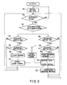
- Fig. 3 shows a flowchart illustrating the teaching and playback control.
- the flowchart shows basic procedures for carrying out a teaching and playback method for a work machine according to the present invention.
- Step S1 initial setting is performed.
- a determination is made, in Step S2, as to whether or not the current mode is an automatic mode. If the current mode is an automatic mode, it is determined, in Step S3, whether it is the teaching mode or the playback mode.
- Step S4 If the current mode is the teaching mode, it is determined, in Step S4, whether or not the teaching switch is turned on, and, in Step S5, whether or not the playback switch is turned off. If affirmative answers are obtained in both of Steps S4 and S5, the memory of the electronic controller is cleared in Step S6. When a signal indicative of the operation Of the work machine lever 1 has been input, the lever signal is stored (Step S7). The teaching mode is terminated when the teaching switch is turned off.
- Step S8 determinations are made as to whether or not the playback switch is turned on (Step S8) and whether or not the teaching switch is turned off (Step S9). If affirmative answers were obtained in both of Steps S8 and S9, the data stored in a memory of the electronic controller is read (Step S10). In Step S11, on the basis of the memory data, a driving signal is output to the electronic hydraulic valve 11. In this step, if an additional signal indicative of the operation of the work machine lever 1 has been added, this signal is also output to the valve 11. When the reading of the memory data has been completed, the playback operation is completed (Step S12).
- the teaching and playback method according to the present invention is applicable to construction equipment.
- the method can be particularly advantageously applied to the hydraulic drive apparatus of a hydraulic excavator.
- the method is applicable to a work machine of any type which has an hydraulic drive apparatus and which is required to perform repeated operations.
Landscapes
- Engineering & Computer Science (AREA)
- Mechanical Engineering (AREA)
- Mining & Mineral Resources (AREA)
- Civil Engineering (AREA)
- General Engineering & Computer Science (AREA)
- Structural Engineering (AREA)
- Operation Control Of Excavators (AREA)
- Fluid-Pressure Circuits (AREA)
- Control Of Position Or Direction (AREA)
Abstract
Description
- The present invention relates to a teaching and playback method for a work machine and, more particularly, to such a method capable of assuring that construction equipment such as a hydraulic excavator performs a playback operation exactly as has been taught, even when a variation has occurred in the load on the machine. The method thus enables the machine to operate with improved accuracy even in such an event.
- Recently, it has often been the case with construction machines that they are required to perform work by repeating a certain operation. This particularly applies to a hydraulic excavator which is required, by the nature of its work, to perform repeated operations during, for example, earth excavation or loading. On the other hand, automatization of construction machines has been propelled by recent development in electronics, as shown in, e.g., Japanese Patent Application No. 149647/1988 (an application previously filed by the same applicant). A conventional teaching and playback method intended to automatize a construction machine of the above-described type has the following arrangement. During teaching, a locus of the work machine is taught by converting, into an electrical signal, the amount by which a work machine operation lever (hereinafter abbreviated to "work machine lever") is operated to move the machine along the locus, and storing the signal in a memory. During reproduction driving, the stored data is read from memory so that the machine performs a playback operation, which is an operation exactly the same as the taught operation.
- With the conventional method, however, the following problem may be encountered in the event that, during a playback operation, the load on the machine should vary from the level upon which the teachings have been formulated. When the load on the machine has varied, particularly when it has increased from the above-mentioned level, there is the risk that the engine output may fall short. The engine rotational speed drops, causing a corresponding drop in the pump discharge. The insufficient pump discharge causes the work machine to move along a locus different from what has been taught. Thus, the machine operates with degraded accuracy. If a load variation occurs during multiple-actuator operation in which a plurality of work machine actuators are operated, there is a risk that the amount of flow supplyed to the actuators may change, also resulting in movement of the machine along a locus different from the taught locus, hence, in degraded accuracy of operation.
- The present invention has been accomplished with a view to overcoming the above-described problem. It is an object of the present invention to provide a teaching and playback method for a work machine that is capable of assuring that a playback operation is performed exactly as specified during teaching, even when, during the playback operation, the machine has encountered a variation in the load from the level applied during the teaching.
- In order to achieve the above-stated object, a teaching and playback method for a work machine according to the present invention comprises the steps of: effecting a teaching mode during teaching where an operation signal indicative of the operator's operation of a plurality of work machine actuators is stored, the mode being effected in such a manner as to store the pump discharge amount and the amounts of flow supplied to the actuator that are present during the teaching; effecting a playback mode in which the actuators are operated in accordance with the data stored during the teaching mode so that the actuators perform the same operation as that by the operator; and effecting a control mode in which, when a variation in the load has been detected during the playback mode, the output of the engine linked with the pump is controlled and the flows supplied to the individual actuators are adjusted in such a manner that the actual pump discharge and the actual flows supplied to the actuators become equal to the stored pump discharge amount and the stored actuator flow supply amounts, respectively.
- The method according to the invention is such that, even when, during playback, the load changes to become different from the level applied during the teaching, pump discharge compensation through the engine output control, as well as compensation for the flows supplied to the actuators, enables a playback operation to be performed exactly as specified by teachings. The method thus overcomes the above-described problem. For this purpose, the engine output during teaching is reduced to a level of the order of 80 % of the rated output, thereby providing a certain margin. When, during playback, the load has increased, the variation in the load causes a drop in the engine output and a corresponding drop in the pump discharge. According to the present invention, when the pump discharge has dropped, the engine output is automatically increased to maintain the pump discharge at the amount that was present during the teaching, thereby assuring that the same operation as specified by the teachings will be performed. If a variation in the load has occurred during multiple-actuator operation, the method uses a pressure compensated flow control valve disposed in an inflow circuit through which the actuators are supplied with flow. The valve is operated to adjust, i.e., increase or decrease, the flows supplied to the actuators in such a manner that the actual flows will become equal to the amounts that were present during the teaching, thereby assuring that exactly the same operation as the taught operation will be performed.
- Therefore, the method according to the present invention is capable of, in addition to various advantages inherent in a teaching and playback method, overcoming the problem conventionally encountered, i.e., a variation in the load causing a deviation in the playback movement, more specifically, a discrepancy in the locus of the work machine from that taught during teaching. The method overcomes the problem by maintaining, through engine output control, the pump discharge at a certain amount and by maintaining, through flow adjustment, the flows supplied to the actuators at certain amounts. Consequently, the operation during playback can be performed with improved accuracy. This is a great improvement in the automatization of work machines.
-
- Fig. 1 is a circuit diagram of a circuit for the teaching and playback control of a work machine to which an embodiment of the present invention is applied;
- Fig. 2 is a circuit diagram of a control circuit having electronic poppet valves substituting an electronic hydraulic valve of the circuit shown in Fig. 1; and
- Fig. 3 is a flowchart showing control performed in the embodiment shown in Fig. 1.
- Certain embodiments of the present invention will now be described with reference to the drawings.
- Fig. 1 shows a circuit for the teaching and playback control of a work machine (not shown), such as a hydraulic excavator, to which an embodiment of the present invention is applied. The control circuit includes a
work machine lever 1, a device 2 for converting the operation amount of the work machine lever 1 into an electrical signal, anautomatization controller 3, an electronic controller 4, adevice 5 for controlling the amount of fuel injected into anengine 6, and a variable-displacement pump 8 connected to theengine 6. Thepump 8 has aregulator 7. Anactuator 10, an electronichydraulic valve 11 and a pressure compensatedflow control valve 12 are connected to aninflow circuit 9 which is in turn connected to thepump 8. - Although not shown, the hydraulic excavator has a plurality of work machine pump levers, and a plurality of actuators corresponding thereto. Since the levers or the actuators have the same construction, only one of the levers and the corresponding actuator are illustrated and will be described so as to avoid reader's confusion.
- The automatization controller 3 (hereinafter abbreviated to "AC") comprises an
input interface 13, acircuit 14 for performing calculation and control on the basis of the signal input through theinterface 13, acircuit 15 for storing processing procedures, constants, etc., and anoutput interface 16 for outputting the values obtained by the calculation and control. During teaching, theAC 3 converts the work machine lever operation amount into an electric signal, stores the signal, and performs the necessary calculation. During playback, the AC 3 transmits the stored data to the electronic controller 4 by generating an output signal. - The AC 3 is connected with
switches switch 17 is a mode changeover switch for changing from one of the manual mode (designated by "OFF" in Fig. 1), the automatic teaching mode ("T"), and the automatic playback mode (P).to another of these three modes. Theswitches - The electronic controller 4 (hereinafter abbreviated to "EC") is connected, via
signal circuits hydraulic valve 11. During playback, the EC 4 operates thevalve 11 on the basis of the signal input from theAC 3 so as to control, through theactuator 10, a playback operation of the work machine. During playback, in order to cope with a variation in the load, the EC 4 receives feedback input signals and sends, on the basis of these input signals, command signals for the control of various members. For this purpose, the EC 4 is connected with the engine fuelinjection control device 5 via input/output signal circuits regulator 7 of the variable-displacement pump 8 via input/output signal circuits flow control valve 12 via input/output signal circuits flow control valve 12 is controlled in a similar manner in proportion to a variation value, so that the flow supplied to theactuator 10 will be maintained at the flow supply amount that was present during the teaching. - Specifically, the EC 4 stores signals output from the
pump 8 and theflow control valve 12 during the teaching. When a change in the discharge of thepump 8, caused by a variation in the load on the actuator, has been detected, the EC 4 operates to output an engine rotational speed adjusting signal to the fuelinjection control device 5 of theengine 6 which is directly connected to thepump 8, thereby performing control in such a manner that the discharge of thepump 8 will become equal to the discharge amount that was present during the teaching. On the other hand, there are a plurality ofactuators 10, each associated with aflow control valve 12 and an electronichydraulic valve 11, whichactuators 10 may be driven in a suitable combination thereof during a multiple-actuator operation. If such an operation is performed during playback, the actual flows which are present during the playback operation are compared with the flow amounts which were present during the teaching. The EC 4 performs control, with or without a variation in the load, in such a manner that the actual flows will become equal to the flow amounts during the teaching. - The EC 4 has a construction similar to that of the above-described
AC 3, and comprises an input interface 28, acontrol circuit 29 for performing calculation and control on the basis of the signal input through the interface 28, acircuit 30 for storing processing procedures, constants, etc., and anoutput interface 31 for outputting the values obtained by the calculation and control. - The electronic
hydraulic valve 11 is, as described above, used to control the operation of theactuator 10. A voltage indicative of the operation amount of thework machine lever 1 is input to thevalve 11, and command currents are applied to twosolenoids valve 11, with the relationship of the command currents being calculated and controlled. The electronichydraulic valve 11 may be substituted byelectronic poppet valves 34a to 34d, as shown in Fig 2. With this substitution, when signals expressing the command currents from the EC 4 are input to twosolenoids poppet valve 34a and a meter-outpoppet valve 34b open in response to and in accordance with the signals, whereby a command flow in accordance with the command currents is supplied to theactuator 10. - Next, description will be given of the manner and procedure of operations performed by the teaching and playback control circuit.
- The teaching mode (T) is selected by switching the position of the
mode changeover switch 17. Subsequently, theteaching switch 18 is turned on to start a teaching operation. When thework machine lever 1 is moved to the desired direction, the amount by which the lever is operated is input, as an electrical signal, to theAC 3, and is then stored therein. The electrical signal indicative of the lever operation amount is also input, through the EC 4, to thesolenoids hydraulic valve 11. Through the control of thevalve 11, theactuator 10 is operated in such a manner that the work machine moves along a predetermined locus, the machine thus being taught. The teaching mode is terminated by turning off theswitch 18. - Prior to the start of a playback operation, the posture of the work machine is set. Thereafter, the
mode changeover switch 17 is operated to select the playback mode (P). Then, theplayback switch 19 is turned on, thereby starting a playback operation. - The playback operation is repeated until the
playback switch 19 is turned off. When, during the playback, the load has varied from the level applied during the teaching, no special operation from the operator is required. Instead, the engine output is automatically controlled in such a manner as to maintain the pump discharge at the amount that was present during the teaching. When a load variation has occurred during a multiple-actuator operation, the pressure compensatedflow control valve 12 is adopted to adjust the flows in such a manner that they are maintained at the amounts that were present during the teaching. Thus, the playback can be performed exactly as specified by the teaching. - When, during the playback, the operator operates the
work machine lever 1, an additional signal is added to theAC 3 so that the electronichydraulic valve 11 and theactuator 10 are operated in accordance with the additional signal as well. - Fig. 3 shows a flowchart illustrating the teaching and playback control. The flowchart shows basic procedures for carrying out a teaching and playback method for a work machine according to the present invention. In Step S1, initial setting is performed. A determination is made, in Step S2, as to whether or not the current mode is an automatic mode. If the current mode is an automatic mode, it is determined, in Step S3, whether it is the teaching mode or the playback mode.
- If the current mode is the teaching mode, it is determined, in Step S4, whether or not the teaching switch is turned on, and, in Step S5, whether or not the playback switch is turned off. If affirmative answers are obtained in both of Steps S4 and S5, the memory of the electronic controller is cleared in Step S6. When a signal indicative of the operation Of the
work machine lever 1 has been input, the lever signal is stored (Step S7). The teaching mode is terminated when the teaching switch is turned off. - On the other hand, if the current mode is the playback mode, determinations are made as to whether or not the playback switch is turned on (Step S8) and whether or not the teaching switch is turned off (Step S9). If affirmative answers were obtained in both of Steps S8 and S9, the data stored in a memory of the electronic controller is read (Step S10). In Step S11, on the basis of the memory data, a driving signal is output to the electronic
hydraulic valve 11. In this step, if an additional signal indicative of the operation of thework machine lever 1 has been added, this signal is also output to thevalve 11. When the reading of the memory data has been completed, the playback operation is completed (Step S12). - The teaching and playback method according to the present invention is applicable to construction equipment. The method can be particularly advantageously applied to the hydraulic drive apparatus of a hydraulic excavator. The method is applicable to a work machine of any type which has an hydraulic drive apparatus and which is required to perform repeated operations.
Claims (3)
- A teaching and playback method for a work machine comprising the steps of:
effecting a teaching mode during teaching where an operation signal indicative of the operator's operation of a plurality of work machine actuators is stored, the mode being effected in such a manner as to store the pump discharge amount and the amounts of flow supplied to said actuator that are present during the teaching;
effecting a playback mode in which said actuators are operated in accordance with the data stored during the teaching mode so that said actuators perform the same operation as that by the operator; and
effecting a control mode in which, when a variation in the load has been detected during the playback mode, the output of the engine linked with the pump is controlled and the flows supplied to the individual actuators are adjusted in such a manner that the actual pump discharge and the actual flows supplied to said actuators become equal to the stored pump discharge amount and the stored actuator flow supply amounts, respectively. - A teaching and a playback method for a work machine according to claim 1, wherein, in said teaching mode, the engine output is reduced to a value smaller than the rated output of the engine, which value is then stored as the engine output to be used during said playback mode, and wherein, in said control mode entered upon the detection of a variation in the load during said playback mode, the actual engine output is controlled.
- A teaching and a playback method for a work machine according to claim 1, wherein, in said control mode entered upon the detection of a variation in the load during said playback mode, the actual flows supplied to said actuators are adjusted by a pressure compensated flow control valve disposed in an inflow circuit connected to said actuators.
Applications Claiming Priority (3)
| Application Number | Priority Date | Filing Date | Title |
|---|---|---|---|
| JP321785/88 | 1988-12-19 | ||
| JP63321785A JP2525233B2 (en) | 1988-12-19 | 1988-12-19 | Work equipment teaching / playback method |
| PCT/JP1989/001270 WO1990007032A1 (en) | 1988-12-19 | 1989-12-18 | Teaching/playback method of working machine |
Publications (3)
| Publication Number | Publication Date |
|---|---|
| EP0448716A1 true EP0448716A1 (en) | 1991-10-02 |
| EP0448716A4 EP0448716A4 (en) | 1992-08-26 |
| EP0448716B1 EP0448716B1 (en) | 1995-10-18 |
Family
ID=18136395
Family Applications (1)
| Application Number | Title | Priority Date | Filing Date |
|---|---|---|---|
| EP90900989A Expired - Lifetime EP0448716B1 (en) | 1988-12-19 | 1989-12-18 | Teaching/playback method of working machine |
Country Status (5)
| Country | Link |
|---|---|
| US (1) | US5274557A (en) |
| EP (1) | EP0448716B1 (en) |
| JP (1) | JP2525233B2 (en) |
| DE (1) | DE68924596T2 (en) |
| WO (1) | WO1990007032A1 (en) |
Cited By (9)
| Publication number | Priority date | Publication date | Assignee | Title |
|---|---|---|---|---|
| GB2252642A (en) * | 1990-12-31 | 1992-08-12 | Samsung Heavy Ind | System for automatically controlling operation of construction vehicle |
| EP0446353A4 (en) * | 1989-09-26 | 1993-03-10 | Kabushiki Kaisha Komatsu Seisakusho | Operation automating apparatus of hydraulic driving machine |
| FR2683238A1 (en) * | 1991-11-06 | 1993-05-07 | Faucheux Ind Sa | Device for manipulating loads, particularly for an agricultural vehicle |
| EP0598936A1 (en) * | 1992-11-25 | 1994-06-01 | Samsung Heavy Industries Co., Ltd | Method of controlling multitasking excavator system |
| EP1044591A3 (en) * | 1999-04-14 | 2002-04-17 | Deere & Company | Function management system for vehicles |
| EP0934562A4 (en) * | 1997-07-07 | 2003-03-26 | Case Corp | Sequential command repeater system for off-road vehicles |
| EP1316868A1 (en) * | 2001-12-03 | 2003-06-04 | Cnh U.K. Limited | Headland routine for agricultural vehicle |
| EP1153342B1 (en) * | 1999-01-21 | 2015-07-15 | Case Corporation | Apparatus and method for preventing an automatic operation sequence in a work vehicle |
| CN107055361A (en) * | 2017-05-16 | 2017-08-18 | 北京航天发射技术研究所 | A kind of steady control method of the hydraulic hoisting machine speed of service and control system |
Families Citing this family (25)
| Publication number | Priority date | Publication date | Assignee | Title |
|---|---|---|---|---|
| JP2682891B2 (en) * | 1990-07-25 | 1997-11-26 | 新キャタピラー三菱株式会社 | Excavator control equipment for power shovel |
| KR950001446A (en) * | 1993-06-30 | 1995-01-03 | 경주현 | How to control automatic repetitive work of excavator |
| JPH07127607A (en) * | 1993-09-07 | 1995-05-16 | Yutani Heavy Ind Ltd | Hydraulic device of work machine |
| US5493798A (en) * | 1994-06-15 | 1996-02-27 | Caterpillar Inc. | Teaching automatic excavation control system and method |
| US5553407A (en) | 1995-06-19 | 1996-09-10 | Vermeer Manufacturing Company | Excavator data acquisition and control system and method of use |
| US5908458A (en) * | 1997-02-06 | 1999-06-01 | Carnegie Mellon Technical Transfer | Automated system and method for control of movement using parameterized scripts |
| US6064933A (en) * | 1997-05-16 | 2000-05-16 | Caterpillar Inc. | Automatic bucket loading using teaching and playback modes triggered by pile contact |
| US6061617A (en) * | 1997-10-21 | 2000-05-09 | Case Corporation | Adaptable controller for work vehicle attachments |
| US6278955B1 (en) | 1998-12-10 | 2001-08-21 | Caterpillar Inc. | Method for automatically positioning the blade of a motor grader to a memory position |
| US6286606B1 (en) | 1998-12-18 | 2001-09-11 | Caterpillar Inc. | Method and apparatus for controlling a work implement |
| US6615114B1 (en) * | 1999-12-15 | 2003-09-02 | Caterpillar Inc | Calibration system and method for work machines using electro hydraulic controls |
| WO2002033443A2 (en) | 2000-06-14 | 2002-04-25 | Vermeer Manufacturing Company | Utility mapping and data distribution system and method |
| DE112004000751B4 (en) * | 2003-05-07 | 2012-11-15 | Komatsu Ltd. | Work machine with engine control device |
| CN101730773B (en) * | 2007-07-13 | 2012-05-23 | 沃尔沃建筑设备公司 | A method for providing an operator of a work machine with operation instructions and a computer program for implementing the method |
| US8185290B2 (en) * | 2008-03-07 | 2012-05-22 | Caterpillar Inc. | Data acquisition system indexed by cycle segmentation |
| US8024095B2 (en) | 2008-03-07 | 2011-09-20 | Caterpillar Inc. | Adaptive work cycle control system |
| US8156048B2 (en) * | 2008-03-07 | 2012-04-10 | Caterpillar Inc. | Adaptive payload monitoring system |
| US8989971B2 (en) * | 2008-05-27 | 2015-03-24 | Eaton Corporation | Method and apparatus for detecting and compensating for pressure transducer errors |
| CN104335065B (en) | 2012-03-12 | 2017-08-25 | 弗米尔公司 | Deviation frequency homodyne GPR |
| GB2521550B (en) | 2012-09-25 | 2016-11-02 | Volvo Constr Equip Ab | Automatic grading system for construction machine and method for controlling the same |
| CN104995386B (en) * | 2013-03-06 | 2017-09-26 | 日立建机株式会社 | construction machinery |
| US9739133B2 (en) | 2013-03-15 | 2017-08-22 | Vermeer Corporation | Imaging underground objects using spatial sampling customization |
| US20140305012A1 (en) * | 2013-04-10 | 2014-10-16 | Caterpillar Inc. | Single boom system having dual arm linkage |
| CN105605035B (en) * | 2016-03-17 | 2017-08-25 | 四川川润液压润滑设备有限公司 | A kind of constant pressure hydraulic thrust control system and control method for sludge plunger pump |
| JP7677825B2 (en) * | 2021-04-30 | 2025-05-15 | 株式会社小松製作所 | Control device and control method for loading machine |
Family Cites Families (9)
| Publication number | Priority date | Publication date | Assignee | Title |
|---|---|---|---|---|
| US4288196A (en) * | 1979-06-14 | 1981-09-08 | Sutton Ii James O | Computer controlled backhoe |
| JPS59220534A (en) * | 1983-05-31 | 1984-12-12 | Komatsu Ltd | Automatic excavator of power shovel |
| JPS60172712A (en) * | 1984-02-17 | 1985-09-06 | Hitachi Constr Mach Co Ltd | Motion regenerating device for working device |
| JPS6288804A (en) * | 1985-10-15 | 1987-04-23 | Hitachi Constr Mach Co Ltd | Hydraulic driving device |
| JP2726997B2 (en) * | 1988-06-17 | 1998-03-11 | 株式会社 小松製作所 | Work automation equipment for construction machinery |
| GB2225127B (en) * | 1988-11-18 | 1993-03-31 | Kubota Ltd | Pivotal movement control device for boom-equipped working machine |
| US5170342A (en) * | 1988-11-22 | 1992-12-08 | Kabushiki Kaisha Komatsu Seisakusho | Method and apparatus for automating a routine operation of electronically controlled hydraulic-powered machine |
| US5065326A (en) * | 1989-08-17 | 1991-11-12 | Caterpillar, Inc. | Automatic excavation control system and method |
| JP3053311B2 (en) * | 1993-04-05 | 2000-06-19 | 株式会社日立製作所 | Air flow meter |
-
1988
- 1988-12-19 JP JP63321785A patent/JP2525233B2/en not_active Expired - Lifetime
-
1989
- 1989-12-18 DE DE68924596T patent/DE68924596T2/en not_active Expired - Fee Related
- 1989-12-18 US US07/720,502 patent/US5274557A/en not_active Expired - Fee Related
- 1989-12-18 WO PCT/JP1989/001270 patent/WO1990007032A1/en not_active Ceased
- 1989-12-18 EP EP90900989A patent/EP0448716B1/en not_active Expired - Lifetime
Non-Patent Citations (1)
| Title |
|---|
| See references of WO9007032A1 * |
Cited By (14)
| Publication number | Priority date | Publication date | Assignee | Title |
|---|---|---|---|---|
| EP0446353A4 (en) * | 1989-09-26 | 1993-03-10 | Kabushiki Kaisha Komatsu Seisakusho | Operation automating apparatus of hydraulic driving machine |
| GB2252642A (en) * | 1990-12-31 | 1992-08-12 | Samsung Heavy Ind | System for automatically controlling operation of construction vehicle |
| GB2252642B (en) * | 1990-12-31 | 1995-05-24 | Samsung Heavy Ind | System for automatically controlling operation of construction vehicle |
| FR2683238A1 (en) * | 1991-11-06 | 1993-05-07 | Faucheux Ind Sa | Device for manipulating loads, particularly for an agricultural vehicle |
| EP0598936A1 (en) * | 1992-11-25 | 1994-06-01 | Samsung Heavy Industries Co., Ltd | Method of controlling multitasking excavator system |
| EP0934562A4 (en) * | 1997-07-07 | 2003-03-26 | Case Corp | Sequential command repeater system for off-road vehicles |
| EP0934562B2 (en) † | 1997-07-07 | 2015-08-05 | CNH Industrial Belgium nv | Sequential command repeater system for off-road vehicles |
| EP1153342B1 (en) * | 1999-01-21 | 2015-07-15 | Case Corporation | Apparatus and method for preventing an automatic operation sequence in a work vehicle |
| EP1044591A3 (en) * | 1999-04-14 | 2002-04-17 | Deere & Company | Function management system for vehicles |
| EP1915893A1 (en) * | 1999-04-14 | 2008-04-30 | Deere & Company | Function management system for vehicles |
| EP1316868A1 (en) * | 2001-12-03 | 2003-06-04 | Cnh U.K. Limited | Headland routine for agricultural vehicle |
| US6980895B2 (en) * | 2001-12-03 | 2005-12-27 | Cnh America Llc | Electronic control system for agricultural vehicle |
| EP1873602A1 (en) * | 2001-12-03 | 2008-01-02 | Cnh U.K. Limited | Headland routine for agricultural vehicle |
| CN107055361A (en) * | 2017-05-16 | 2017-08-18 | 北京航天发射技术研究所 | A kind of steady control method of the hydraulic hoisting machine speed of service and control system |
Also Published As
| Publication number | Publication date |
|---|---|
| US5274557A (en) | 1993-12-28 |
| EP0448716A4 (en) | 1992-08-26 |
| EP0448716B1 (en) | 1995-10-18 |
| DE68924596D1 (en) | 1995-11-23 |
| WO1990007032A1 (en) | 1990-06-28 |
| JP2525233B2 (en) | 1996-08-14 |
| JPH02164940A (en) | 1990-06-25 |
| DE68924596T2 (en) | 1996-04-04 |
Similar Documents
| Publication | Publication Date | Title |
|---|---|---|
| EP0448716B1 (en) | Teaching/playback method of working machine | |
| US5359517A (en) | Method and device for automating operation of construction machine | |
| US6438953B1 (en) | Control device for hydraulic drive machine | |
| JP3805383B2 (en) | Control device for integrating work attachments into fluid systems | |
| EP0781888B1 (en) | Hydraulic circuit for hydraulic shovel | |
| US4759183A (en) | Control arrangement for at least two hydraulic loads fed by at least one pump | |
| CA2180871C (en) | Device and method for controlling attachment of construction machine | |
| EP0783057A1 (en) | Hydraulic drive system for construction machines | |
| US6170262B1 (en) | Control device for hydraulically driven equipment | |
| EP0362402B1 (en) | Method and apparatus for driving hydraulic machine | |
| JP4136041B2 (en) | Hydraulic drive device for hydraulic working machine | |
| EP0193947B1 (en) | Power transmission | |
| KR950009324B1 (en) | Actuator automatic speed regulating device and its control method | |
| US5317871A (en) | Circuit capable of varying pump discharge volume in closed center-load sensing system | |
| JPH0610906A (en) | Fluid pressure controller | |
| WO1994005917A1 (en) | Controller of hydraulic driving machine | |
| JPH03208103A (en) | Automatic control device for controlling process of movement of at least one working device to be controlle by operation element | |
| JPH09296482A (en) | Operational system selection device of hydraulic construction machine and method therefor | |
| EP0526639B1 (en) | Device for controlling height of blade of tracked vehicle | |
| JP3018788B2 (en) | Hydraulic pump control circuit | |
| JPH04285301A (en) | Hydraulic circuit for improving work accuracy in load sensing system | |
| JP2644307B2 (en) | Hydraulic circuit for industrial vehicles | |
| JPH07107281B2 (en) | Construction machine work automation method and device | |
| KR100256775B1 (en) | A controlling apparatus and method of hydraulic type construction mechanics | |
| JP3565871B2 (en) | Control method of engine for driving hydraulic pump |
Legal Events
| Date | Code | Title | Description |
|---|---|---|---|
| PUAI | Public reference made under article 153(3) epc to a published international application that has entered the european phase |
Free format text: ORIGINAL CODE: 0009012 |
|
| 17P | Request for examination filed |
Effective date: 19910607 |
|
| AK | Designated contracting states |
Kind code of ref document: A1 Designated state(s): DE FR GB |
|
| A4 | Supplementary search report drawn up and despatched |
Effective date: 19920707 |
|
| AK | Designated contracting states |
Kind code of ref document: A4 Designated state(s): DE FR GB |
|
| 17Q | First examination report despatched |
Effective date: 19930903 |
|
| GRAA | (expected) grant |
Free format text: ORIGINAL CODE: 0009210 |
|
| AK | Designated contracting states |
Kind code of ref document: B1 Designated state(s): DE FR GB |
|
| PG25 | Lapsed in a contracting state [announced via postgrant information from national office to epo] |
Ref country code: FR Effective date: 19951018 |
|
| REF | Corresponds to: |
Ref document number: 68924596 Country of ref document: DE Date of ref document: 19951123 |
|
| PGFP | Annual fee paid to national office [announced via postgrant information from national office to epo] |
Ref country code: FR Payment date: 19951212 Year of fee payment: 7 |
|
| EN | Fr: translation not filed | ||
| PLBE | No opposition filed within time limit |
Free format text: ORIGINAL CODE: 0009261 |
|
| STAA | Information on the status of an ep patent application or granted ep patent |
Free format text: STATUS: NO OPPOSITION FILED WITHIN TIME LIMIT |
|
| 26N | No opposition filed | ||
| PGFP | Annual fee paid to national office [announced via postgrant information from national office to epo] |
Ref country code: GB Payment date: 19971209 Year of fee payment: 9 |
|
| PG25 | Lapsed in a contracting state [announced via postgrant information from national office to epo] |
Ref country code: GB Free format text: LAPSE BECAUSE OF NON-PAYMENT OF DUE FEES Effective date: 19981218 |
|
| PGFP | Annual fee paid to national office [announced via postgrant information from national office to epo] |
Ref country code: DE Payment date: 19981229 Year of fee payment: 10 |
|
| GBPC | Gb: european patent ceased through non-payment of renewal fee |
Effective date: 19981218 |
|
| PG25 | Lapsed in a contracting state [announced via postgrant information from national office to epo] |
Ref country code: DE Free format text: LAPSE BECAUSE OF NON-PAYMENT OF DUE FEES Effective date: 20001003 |