EP0447886A1 - Axial flow gas turbine - Google Patents
Axial flow gas turbine Download PDFInfo
- Publication number
- EP0447886A1 EP0447886A1 EP91103525A EP91103525A EP0447886A1 EP 0447886 A1 EP0447886 A1 EP 0447886A1 EP 91103525 A EP91103525 A EP 91103525A EP 91103525 A EP91103525 A EP 91103525A EP 0447886 A1 EP0447886 A1 EP 0447886A1
- Authority
- EP
- European Patent Office
- Prior art keywords
- turbine
- compressor
- rotor
- drum
- cooling air
- Prior art date
- Legal status (The legal status is an assumption and is not a legal conclusion. Google has not performed a legal analysis and makes no representation as to the accuracy of the status listed.)
- Granted
Links
Images

Classifications
-
- F—MECHANICAL ENGINEERING; LIGHTING; HEATING; WEAPONS; BLASTING
- F01—MACHINES OR ENGINES IN GENERAL; ENGINE PLANTS IN GENERAL; STEAM ENGINES
- F01D—NON-POSITIVE DISPLACEMENT MACHINES OR ENGINES, e.g. STEAM TURBINES
- F01D3/00—Machines or engines with axial-thrust balancing effected by working-fluid
- F01D3/04—Machines or engines with axial-thrust balancing effected by working-fluid axial thrust being compensated by thrust-balancing dummy piston or the like
-
- F—MECHANICAL ENGINEERING; LIGHTING; HEATING; WEAPONS; BLASTING
- F01—MACHINES OR ENGINES IN GENERAL; ENGINE PLANTS IN GENERAL; STEAM ENGINES
- F01D—NON-POSITIVE DISPLACEMENT MACHINES OR ENGINES, e.g. STEAM TURBINES
- F01D5/00—Blades; Blade-carrying members; Heating, heat-insulating, cooling or antivibration means on the blades or the members
- F01D5/02—Blade-carrying members, e.g. rotors
- F01D5/08—Heating, heat-insulating or cooling means
- F01D5/081—Cooling fluid being directed on the side of the rotor disc or at the roots of the blades
- F01D5/084—Cooling fluid being directed on the side of the rotor disc or at the roots of the blades the fluid circulating at the periphery of a multistage rotor, e.g. of drum type
Landscapes
- Engineering & Computer Science (AREA)
- Mechanical Engineering (AREA)
- General Engineering & Computer Science (AREA)
- Turbine Rotor Nozzle Sealing (AREA)
- Structures Of Non-Positive Displacement Pumps (AREA)
Abstract
Description
Die Erfindung betrifft eine axialdurchströmte Gasturbine, im wesentlichen bestehend aus einer mehrstufigen Turbine, welche unter anderm einen auf einer gemeinsamen Welle angeordneten Verdichter antreibt,
- bei welcher der zwischen Turbine und Verdichter liegende Wellenteil eine Trommel ist, die von einer Trommelabdeckung umgeben ist, und bei welcher der zwischen Trommel und Trommelabdeckung gebildete Ringkanal die Führung der aus dem Verdichter entnommenen Kühlluft zur Stirnseite des Turbinenrotors und daran anschliessend zu deren rotorseitigen Kühlkanälen übernimmt,
- und wozu zur Dichtung zwischen den Druckniveaus am Austritt des Verdichters und am Eintritt der Kühlluft in die Turbine auf der Trommel eine gegen die Trommelabdeckung dichtende Labyrinthdichtung angeordnet ist,
- wobei die gesamte rotorseitige Kühlluft für die Turbine dem Verdichter im Bereich des Verdichteraustritts entnommen wird.
- in which the shaft part lying between the turbine and the compressor is a drum, which is surrounded by a drum cover, and in which the ring channel formed between the drum and the drum cover takes over the routing of the cooling air removed from the compressor to the front side of the turbine rotor and then to the rotor-side cooling channels thereof ,
- and for what purpose a labyrinth seal sealing against the drum cover is arranged on the drum between the pressure levels at the outlet of the compressor and at the inlet of the cooling air into the turbine,
- the entire rotor-side cooling air for the turbine is taken from the compressor in the region of the compressor outlet.
Derartige Gasturbinen sind bekannt. Die gesamte rotorseitige Kühlluft wird aus dem Sammelraum zwischen Verdichter und Turbine entnommen; der überwiegende Teil davon strömt direkt über ein Beschleunigungsgitter in die Rotorkühlkanäle ein. Hierbei befindet sich das Beschleunigungsgitter in der Regel auf dem gleichen Radius wie die Rotorkühlkanäle an der Stirnseite des Turbinenrotors. Der kleinere Anteil Kühlluft, d.h. die zur Kühlung der letzten Verdichterscheibe sowie der Trommel und der ersten Turbinenscheibe notwendige Luft muss zur Wahrnehmung der Kühlfunktion in einem Kühler rückgekühlt werden, bevor er drallfrei in den Ringkanal eingeleitet wird. Diese Lösung hat eine Reihe von Unzulänglichkeiten zur Folge.
- Zum einen hat die Kühlluft, da aus dem Sammelraum entnommen, nicht die höchstmögliche und erwünschte Reinheit, wie es insbesondere die feinen Schaufelkühlkanäle verlangen.
- Zum andern wird ein separater, kostspieliger Apparat für die Rückkühlung benötigt.
- Ferner wird dieser kleinere, rückgekühlte Luftanteil infolge der konvektiven Aufheizung auf seinem Weg bis zum Eintritt in den Ringkanal wiederum stark aufgeheizt, wodurch die Kühlwirkung reduziert wird.
- Zudem bewirkt die drallfreie Einführung der Luft eine zusätzliche Erhöhung der adiabaten Wandtemperatur in den betroffenen Bereichen.
- Schliesslich bewirkt die drallfreie Einführung der Kühlluft in den Ringkanal ausserdem eine hohe Wärmeübergangszahl α im ganzen beaufschlagten Rotorbereich, was zusammen mit der erwähnten erhöhten Kühllufttemperatur hohe transiente Spannungen verursachen kann.
- Ueberdies ergeben sich im Bereich des Trommellabyrinthes extrem hohe α-Zahlen mit den bekannten Nachteilen.
- Bei diesen bekannten Gasturbinen wird bewusst eine Rückströmung, d.h. eine Einströmung von ruckgekühlter Luft aus dem Ringkanal in den Hauptkanal des Verdichters hinter dessen letzte Laufreihe in Kauf genommen. Es versteht sich, dass durch diese Massnahme eine nicht unbeträchtliche Störung des Hauptströmung erfolgt.
- Dadurch, dass die Einströmung in die Rotorkühlkanäle zwangsläufig mit geringen Drall erfolgt, muss der Rotor Pumparbeit leisten, was die Kühllufttemperatur weiterhin anhebt.
- On the one hand, the cooling air, since it is removed from the collecting space, does not have the highest possible and desired purity, as required in particular by the fine blade cooling channels.
- Secondly, a separate, costly apparatus for recooling is required.
- Furthermore, this smaller, recooled portion of air is again heated up strongly as a result of the convective heating on its way to the entry into the ring channel, as a result of which the cooling effect is reduced.
- In addition, the swirl-free introduction of air causes an additional increase in the adiabatic wall temperature in the affected areas.
- Finally, the swirl-free introduction of the cooling air into the ring channel also results in a high heat transfer coefficient α in the entire rotor area, which, together with the increased cooling air temperature mentioned, can cause high transient voltages.
- In addition, extremely high α numbers result in the area of the drum labyrinth with the known disadvantages.
- In these known gas turbines, a backflow, that is to say an inflow of recooled air from the annular duct into the main duct of the compressor behind its last running row, is accepted. It goes without saying that this measure causes a not inconsiderable disturbance of the main flow.
- Because the inflow into the rotor cooling channels inevitably takes place with little swirl, the rotor has to do pumping work, which further increases the cooling air temperature.
Die Erfindung versucht all diese Nachteile zu vermeiden. Desweiteren liegt ihr noch die zusätzliche Aufgabe zugrunde, bei axial durchströmten Gasturbinen der eingangs genannten Art, welche turbinenseitig grossdimensionierte Rotorstirnflächen aufweisen, den Axialschub zu verringern.The invention tries to avoid all these disadvantages. Furthermore, it is based on the additional task of reducing the axial thrust in the case of axially flowing gas turbines of the type mentioned at the outset, which have large rotor end faces on the turbine side.
Erfindungsgemäss wird dies dadurch erreicht, dass die rotorseitige Kühlluft für die Turbine nach der letzten Laufreihe des Verdichters an dessen Nabe entnommen und mit dem ihr anhaftenden Drall unmittelbar in den Ringkanal geleitet wird, und dass diese Kühlluft innerhalb des Ringkanals in einem Drallgitter umgelenkt und auf höchstmögliche Tangentialgeschwindigkeit beschleunigt wird.According to the invention, this is achieved in that the rotor-side cooling air for the turbine is removed from the compressor after the last run row of the compressor at its hub and is passed directly into the ring duct with the swirl adhering to it, and in that this cooling air is deflected within the ring duct in a swirl grille and to the highest possible Tangential speed is accelerated.
Die Vorteile der Erfindung sind unter anderem im Wegfall des bisher üblichen aufwendigen Kühlers einerseits und der geringen transienten Spannungen im umspülten Wellenbereich andererseits zu sehen.The advantages of the invention can be seen, inter alia, in the elimination of the previously required complex cooler, on the one hand, and the low transient voltages in the washed-around wave range, on the other.
Es ist besonders zweckmässig, wenn die rotorseitige Kühlluft nach der letzten Laufreihe des Verdichters an dessen Nabe entnommen wird und mit dem ihr anhaftenden Drall in den Ringkanal geleitet wird. Hierdurch wird zum einen gewährleistet, dass die Aufheizung des Rotors über die Kühlluft und somit das Niveau der transienten Spannungen kleinstmöglich ist. Darüberhinaus wird durch die nabenseitige Entnahme reinstmögliche, nahezu staubfreie Luft in den Ringkanal eingeleitet.It is particularly expedient if the cooling air on the rotor side is removed from the compressor after the last running row of the compressor and is passed into the ring channel with the swirl adhering to it. This ensures, on the one hand, that the heating of the rotor via the cooling air and thus the level of the transient voltages is as small as possible. In addition, the purest possible, almost dust-free air is introduced into the ring channel through the hub-side removal.
Ferner ist es vorteilhaft, wenn das Drallgitter im Ringkanal auf einem kleinstmöglichen Radius und möglichst in unmittelbarer Nähe des Radseitenraumes angeordnet ist. Hierbei orientiert sich der kleinstmögliche Radius an der an dieser örtlichen Stelle vorliegenden Schallgeschwindigkeit. Man hat somit ein Mittel in der Hand, den Axialschub zu reduzieren.It is also advantageous if the swirl grille is arranged in the ring channel on the smallest possible radius and as close as possible to the wheel side space. The smallest possible radius is based on the speed of sound at this local point. You thus have a means to reduce the axial thrust.
Schliesslich wird mit Vorteil die gegen die Trommelabdeckung dichtende Labyrinthdichtung zur Senkung der Wärmeübergangszahl α rotorseitig in Segmente unterteilt. Dadurch wird die Wirkung der in Labyrinthen üblicherweise extrem hohen α-Werte unterbunden.Finally, the labyrinth seal that seals against the drum cover is advantageously divided into segments on the rotor side to reduce the heat transfer coefficient α. This prevents the effects of the α values, which are usually extremely high in labyrinths.
In der Zeichnung ist ein Ausführungsbeispiel der Erfindung anhand einer einwelligen axialdurchströmten Gasturbine dargestellt.
Es zeigen:
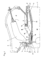
- Fig.1
- einen Teillängsschnitt der Gasturbine;
- Fig.2
- die teilweise Abwicklung eines Zylinderschnittes auf mittlerem Durchmesser des durchströmten Ringkanals;
- Fig.3
- einen Teilquerschnitt durch die Trommel in der Ebene des Labyrinthes.
Show it:
- Fig. 1
- a partial longitudinal section of the gas turbine;
- Fig. 2
- the partial settlement of a cylindrical section on the medium diameter of the flow through the annular channel;
- Fig. 3
- a partial cross section through the drum in the plane of the labyrinth.
Es sind nur die für das Verständnis der Erfindung wesentlichen Elemente gezeigt. Nicht dargestellt sind von der Anlage beispielsweise das Abgasgehäuse der Gasturbine mit Abgasrohr und Kamin sowie die Eintrittspartien des Verdichterteils. Die Strömungsrichtung der Arbeitsmittel ist mit Pfeilen bezeichnet.Only the elements essential for understanding the invention are shown. The system does not show, for example, the exhaust gas casing of the gas turbine with the exhaust pipe and chimney, and the inlet parts of the compressor part. The direction of flow of the work equipment is indicated by arrows.
Die Turbine 1, von der in Fig.1 lediglich die erste axialdurchströmte Stufe 2 in Form einer Leit- und einer Laufreihe dargestellt ist, besteht im wesentlichen aus dem beschaufelten Rotor 3 und dem mit Leitschaufeln bestückten Schaufelträger 4. Der Schaufelträger ist im Turbinengehäuse 5 eingehängt. Im dargestellten Fall umfasst das Turbinengehäuse 5 ebenfalls den Sammelraum 6 für die verdichtete Brennluft. Aus diesem Sammelraum gelangt die Brennluft in die Ringbrennkammer 7, welche ihrerseits in den Turbineneinlass, d.h. stromaufwärts der ersten Leitreihe mündet. In den Sammelraum gelangt die verdichtete Luft aus dem Diffusor 8 des Verdichters 9. Von letzterem ist lediglich die letzte Stufe 10 dargestellt, wobei die Leitbeschaufelung dieser letzten Stufe aus der eigentlichen Leitreihe und der Nachleitreihe besteht. Die Laufbeschaufelung des Verdichters und der Turbine sitzen auf einer gemeinsamen Welle 11, wobei der zwischen Turbine und Verdichter befindliche Teil als Trommel 12 ausgebildet ist.
Diese Trommel ist in ihrer ganzen axialen Erstreckung von einer Trommelabdeckung 13 umgeben, welche über Rippen 14 mit dem Diffusoraussengehäuse 15 des Verdichters befestigt ist. Diese Trommelabdeckung bildet verdichterseitig das Deckband für die Schaufeln der beiden letzten Verdichterleitreihen. Turbinenseitig begrenzt die Trommelabdeckung zusammen mit der Stirnseite 16 des Turbinenrotors einen radial verlaufenden Radseitenraum 17.The turbine 1, of which only the first axially flowed
This drum is surrounded in its entire axial extent by a
Dieser Raum 17 bildet das austrittsseitige Ende eines Ringkanals 18, welcher, ausgehend von der Nabe hinter der letzten Verdichterlaufreihe, zwischen Trommelabdeckung und Trommel verläuft. In diesen Ringkanal wird die gesamte rotorseitige Kühlluft eingeleitet. Bei der Dimensionierung des Ringkanals 18 ist wegen der darin herrschenden drallbehafteten Strömung folgendes zu beachten: Damit die Drallströmung entlang der Trommel nicht instabil wird, müssen Normal- und Tangentialgeschwindigkeit der Kühlluft sowie mittlerer Kanalradius und Kanalhöhe in einer gewissen Relation zueinander stehen, wie es aus der Theorie der Drallströmung bekannt ist.This
Am turbinenseitigen Ende ist auf der Trommel ein gegen die Trommelabdeckung dichtendes Labyrinth 19 angeordnet. Das Labyrinth dichtet indes nur mittelbar gegen die Trommelabdeckung. Sein nichtrotierender Teil ist in einem Labyrinthkörper 24 auf geeignet Art befestigt. Zur Senkung der Wärmeübergangszahl α ist das Labyrinth rotorseitig in eine Anzahl an der Trommeloberfläche angeordneter Segmente unterteilt. In Fig.3 ist die Segmentierung des Labyrinthes 19 dargestellt. Im gezeigten Beispiel handelt es sich um axialgerichtete Hammerkopfnuten 21, welche in einen Bund 22 der Trommel 12 hineingearbeitet sind. In diese Nuten sind sogenannte Wärmestausegmente 20 mit entsprechend konfigurierten Füssen 23 eingehängt. Gegen die in den Ringkanal ragenden Aussenflächen der Wärmestausegmente wirken in Fig.3 nicht dargestellte metallische Dichtstreifen, welche beispielsweise im Labyrinthkörper 24 eingestemmt oder auf sonstige Art befestigt sein können.At the end on the turbine side, a
Gemäss der Erfindung soll nunmehr innerhalb des Ringkanals 18 die Kühlluft in einem Drallgitter umgelenkt und auf höchstmögliche Tangentialgeschwindigkeit beschleunigt werden. Dieses Drallgitter 25 ist im Ringkanal in Form von Dralldüsen unmittelbar gegenüber der Stirnseite 16 des Turbinenrotors vorgesehen, d.h. es mündet direkt in den Radseitenraum 17. Aus später zu erläuternden Gründen ist es zweckmässig, das Drallgitter auf dem kleinstmöglich Radius anzuordnen.According to the invention, the cooling air is now to be deflected in a swirl grille within the
Um den Labyrinthkörper 24 in seiner Lage zu halten, ist er über mehrere am Umfang verteilte strömungsorientierte Tragrippen 26 mit der Trommelabdeckung 13 verbunden.In order to hold the
Der Zylinderschnitt in Fig. 2 zeigt in vergrössertem Masstab den Schaufelplan über dem Labyrinthkörper 24. Hierin bedeuten c die Absolutgeschwindigkeit der Kühlluft und u die Umfangsgeschwindigkeit des Rotors. Zwecks Angabe der Grössenordnung bei einem ausgeführten Beispiel beträgt das Verhältnis Teilung zu Sehne bei den Tragrippen 26 beispielsweise 1,2 und bei den Dralldüsen 25 ca. 0.85. Bei den Tragrippen 26 handelt es sich lediglich um Strömungsrippen mit symmetrischen Profil, in denen der Strömung weder eine Aenderung der Geschwindigkeit noch der Richtung aufgezwungen wird. Die Strömung verlässt die Tragrippen mit der Geschwindigkeit c und einem Winkel von ca. 20° gegen die Umfangsrichtung.The cylinder section in FIG. 2 shows the blade plan over the
Bei den Dralldüsen handelt es sich um ein Beschleunigungsgitter mit geringer Krümmung der Skelettlinie, welches die Strömung von nunmehr ca. 25° auf ca. 10° umlenkt und die Geschwindigkeit von ca. 120 auf ca. 420 m/sec steigert.The swirl nozzles are an acceleration grille with a slight curvature of the skeleton line, which redirects the flow from now approx. 25 ° to approx. 10 ° and increases the speed from approx. 120 to approx. 420 m / sec.
Die Wirkungsweise der Erfindung wird nachstehend anhand eines Zahlenbeispieles erläutert: Es versteht sich, dass auf die Bekanntgabe von allen den Berechnungen und Versuchen zugrundeliegenden Absolutwerten verzichtet wird, da diese wegen ihrer Abhängigkeit von allzu zahlreichen Parametern ohnehin ungenügende Aussagekraft besitzen würden.The mode of operation of the invention is explained below with the aid of a numerical example: It goes without saying that the disclosure of all absolute values on which the calculations and tests are based is dispensed with, since these would in any case have insufficient informative value because of their dependence on too many parameters.
Die gesamte für die Rotorkühlung erforderliche Kühlluft d.h. ca. 8% der verdichteten Luft wird hinter der letzten Laufreihe im Bereich der Nabe entnommen. Durch den Ringkanal 18 strömt die drallbehaftete Kühlluft bis vor das Trommellabyrinth 19. Durch den vom Verdichter her vorgegebenen Drall wird sichergestellt, dass infolge der kleinen Relativgeschwindigkeit zwischen Rotoroberfläche und Kühlluft minimale Wärmeübergangszahlen und tiefstmögliche adiabate Wandtemperaturen erreicht werden. Dies wiederum hat niedrige transiente Spannungen und tiefstmögliche stationäre Temperaturen im betrachteten Bereich zur Folge.The total cooling air required for rotor cooling i.e. Approx. 8% of the compressed air is taken from behind the last row in the area of the hub. The swirling cooling air flows through the
Durch das Labyrinth 19 strömt lediglich die unvermeidliche Leckmenge. Es ist nicht zu umgehen, dass im Labyrinth die Tangentialgeschwindigkeit auf ca. 50% der dortigen Umfangsgeschwindigkeit abgebaut wird. Damit geht bereits ein Teil der obengenannten positiven Drallwirkung verloren. Durch die spezifische Strömungsform im Labyrinth wird zudem der α-Wert erhöht. Abhilfe wird hier geschaffen durch die Segmentierung des rotorseitigen Labyrinthteiles, welche den Wärmefluss in die Trommel stark vermindert. Durch die Tatsache der Drallreduktion innerhalb des Labyrinthes ist es wichtig, dass der auf das Labyrinth folgende Teil des Ausströmkanals 27 so kurz wie möglich bemessen wird, d.h. das Labyrinth ist möglichst nahe an die erste Turbinenscheibe zu verlegen.Only the inevitable amount of leakage flows through the
Der Hauptteil der Rotorkühlluft wird über die strömungsorientierten Tragrippen 26 des Labyrinthkörpers 24 in die Dralldüsen 25 geführt. In diesen erfolgt eine Beschleunigung der Kühlluft bis nahe an die Schallgeschwindigkeit bei gleichzeitiger leichter Umlenkung in Rotordrehrichtung. Die Abströmung aus dem Drallgitter erfolgt dabei nahezu tangential, d.h. ca. 10° zur Umfangsrichtung.The main part of the rotor cooling air is guided into the
Zum einen wirkt sich dieser hoher Drall wiederum positiv auf den Wärmeübergang aus, wie bereits oben beschrieben. Vorteilhafte Werte können erzielt werden, wenn am Eintritt der Kühlluft in den Rotor das Verhältnis Tangentialgeschwindigkeit zu Umfangsgeschwindigkeit um ca. 1 beträgt. Dies bedeutet, dass beim Einströmen in den Rotorkühlkanal kein Arbeitsaustausch erfolgt, d.h. dass dem Rotor weder Arbeit entzogen noch hinzugefügt wird. Insbesondere wird auch die Temperatur der Kühlluft durch Pumparbeit nicht erhöht.On the one hand, this high swirl has a positive effect on the heat transfer, as already described above. Advantageous values can be achieved if the ratio of tangential speed to peripheral speed is around 1 at the entry of the cooling air into the rotor. This means that there is no work exchange when flowing into the rotor cooling duct, i.e. that no work is removed or added to the rotor. In particular, the temperature of the cooling air is not increased by pumping.
Darüberhinaus wird durch das hohe Geschwindigkeitsniveau der statische Druck am Austritt aus dem Drallgitter stark herabgesetzt. Im Radseitenraum herrscht somit ein niedrigerer mittlerer Druck, wodurch der Axialschub des Rotors erniedrigt wird.In addition, the static pressure at the outlet from the swirl grille is greatly reduced by the high speed level. There is therefore a lower mean pressure in the wheel side space, as a result of which the axial thrust of the rotor is reduced.
Selbstverständlich ist die Erfindung nicht auf das gezeigte und beschriebene Ausführungsbeispiel beschränkt. In Abweichung von der Lösung der getrennten Tragrippen und Dralldüsen ist durchaus eine Ausbildung denkbar, bei welcher diese beiden Elemente in einem einzigen Gitter vereinigt werden.Of course, the invention is not limited to the exemplary embodiment shown and described. In a departure from the solution of the separate support ribs and swirl nozzles, an embodiment is quite conceivable in which these two elements are combined in a single grid.
Claims (4)
dadurch gekennzeichnet,
characterized,
Applications Claiming Priority (2)
| Application Number | Priority Date | Filing Date | Title |
|---|---|---|---|
| CH96390 | 1990-03-23 | ||
| CH963/90 | 1990-03-23 |
Publications (2)
| Publication Number | Publication Date |
|---|---|
| EP0447886A1 true EP0447886A1 (en) | 1991-09-25 |
| EP0447886B1 EP0447886B1 (en) | 1994-07-13 |
Family
ID=4199266
Family Applications (1)
| Application Number | Title | Priority Date | Filing Date |
|---|---|---|---|
| EP91103525A Expired - Lifetime EP0447886B1 (en) | 1990-03-23 | 1991-03-07 | Axial flow gas turbine |
Country Status (4)
| Country | Link |
|---|---|
| US (1) | US5189874A (en) |
| EP (1) | EP0447886B1 (en) |
| JP (1) | JP3105277B2 (en) |
| DE (1) | DE59102139D1 (en) |
Cited By (27)
| Publication number | Priority date | Publication date | Assignee | Title |
|---|---|---|---|---|
| FR2707698A1 (en) * | 1993-07-15 | 1995-01-20 | Snecma | Turbomachine provided with means for blowing air on a rotor element. |
| EP0702129A2 (en) | 1994-09-19 | 1996-03-20 | ABB Management AG | Cooling the rotor of an axial gasturbine |
| EP1736635A2 (en) * | 2005-05-31 | 2006-12-27 | Rolls-Royce Deutschland Ltd & Co KG | Air transfer system between compressor and turbine of a gas turbine engine |
| US7334412B2 (en) | 2002-11-11 | 2008-02-26 | Siemens Aktiengesellschaft | Cooling air and injected liquid system for gas turbine blades |
| EP2011963A1 (en) | 2007-07-04 | 2009-01-07 | ALSTOM Technology Ltd | Gas turbine with axial thrust balance |
| DE102013220844A1 (en) | 2013-10-15 | 2015-04-16 | MTU Aero Engines AG | Compressor and gas turbine with such a compressor |
| US10100739B2 (en) | 2015-05-18 | 2018-10-16 | United Technologies Corporation | Cooled cooling air system for a gas turbine engine |
| US10221862B2 (en) | 2015-04-24 | 2019-03-05 | United Technologies Corporation | Intercooled cooling air tapped from plural locations |
| US10371055B2 (en) | 2015-02-12 | 2019-08-06 | United Technologies Corporation | Intercooled cooling air using cooling compressor as starter |
| US10443508B2 (en) | 2015-12-14 | 2019-10-15 | United Technologies Corporation | Intercooled cooling air with auxiliary compressor control |
| US10480419B2 (en) | 2015-04-24 | 2019-11-19 | United Technologies Corporation | Intercooled cooling air with plural heat exchangers |
| US10550768B2 (en) | 2016-11-08 | 2020-02-04 | United Technologies Corporation | Intercooled cooled cooling integrated air cycle machine |
| US10577964B2 (en) | 2017-03-31 | 2020-03-03 | United Technologies Corporation | Cooled cooling air for blade air seal through outer chamber |
| US10669940B2 (en) | 2016-09-19 | 2020-06-02 | Raytheon Technologies Corporation | Gas turbine engine with intercooled cooling air and turbine drive |
| US10711640B2 (en) | 2017-04-11 | 2020-07-14 | Raytheon Technologies Corporation | Cooled cooling air to blade outer air seal passing through a static vane |
| US10718233B2 (en) | 2018-06-19 | 2020-07-21 | Raytheon Technologies Corporation | Intercooled cooling air with low temperature bearing compartment air |
| US10731560B2 (en) | 2015-02-12 | 2020-08-04 | Raytheon Technologies Corporation | Intercooled cooling air |
| US10738703B2 (en) | 2018-03-22 | 2020-08-11 | Raytheon Technologies Corporation | Intercooled cooling air with combined features |
| US10794290B2 (en) | 2016-11-08 | 2020-10-06 | Raytheon Technologies Corporation | Intercooled cooled cooling integrated air cycle machine |
| US10794288B2 (en) | 2015-07-07 | 2020-10-06 | Raytheon Technologies Corporation | Cooled cooling air system for a turbofan engine |
| US10808619B2 (en) | 2018-04-19 | 2020-10-20 | Raytheon Technologies Corporation | Intercooled cooling air with advanced cooling system |
| US10830145B2 (en) | 2018-04-19 | 2020-11-10 | Raytheon Technologies Corporation | Intercooled cooling air fleet management system |
| US10830148B2 (en) | 2015-04-24 | 2020-11-10 | Raytheon Technologies Corporation | Intercooled cooling air with dual pass heat exchanger |
| US10961911B2 (en) | 2017-01-17 | 2021-03-30 | Raytheon Technologies Corporation | Injection cooled cooling air system for a gas turbine engine |
| US10995673B2 (en) | 2017-01-19 | 2021-05-04 | Raytheon Technologies Corporation | Gas turbine engine with intercooled cooling air and dual towershaft accessory gearbox |
| US11255268B2 (en) | 2018-07-31 | 2022-02-22 | Raytheon Technologies Corporation | Intercooled cooling air with selective pressure dump |
| US11808210B2 (en) | 2015-02-12 | 2023-11-07 | Rtx Corporation | Intercooled cooling air with heat exchanger packaging |
Families Citing this family (6)
| Publication number | Priority date | Publication date | Assignee | Title |
|---|---|---|---|---|
| US5555721A (en) * | 1994-09-28 | 1996-09-17 | General Electric Company | Gas turbine engine cooling supply circuit |
| JP4088368B2 (en) * | 1998-06-04 | 2008-05-21 | 三菱重工業株式会社 | Gland deformation prevention structure of low-pressure steam turbine |
| US6234746B1 (en) * | 1999-08-04 | 2001-05-22 | General Electric Co. | Apparatus and methods for cooling rotary components in a turbine |
| CN1329662C (en) * | 2001-12-17 | 2007-08-01 | 乐金电子(天津)电器有限公司 | Vortex compressor |
| AU2009216831B2 (en) * | 2008-02-20 | 2014-11-20 | General Electric Technology Gmbh | Gas turbine |
| US8935926B2 (en) | 2010-10-28 | 2015-01-20 | United Technologies Corporation | Centrifugal compressor with bleed flow splitter for a gas turbine engine |
Citations (8)
| Publication number | Priority date | Publication date | Assignee | Title |
|---|---|---|---|---|
| DE2003947A1 (en) * | 1969-01-29 | 1970-07-30 | Gen Electric | Gas turbine |
| US3826084A (en) * | 1970-04-28 | 1974-07-30 | United Aircraft Corp | Turbine coolant flow system |
| US4236869A (en) * | 1977-12-27 | 1980-12-02 | United Technologies Corporation | Gas turbine engine having bleed apparatus with dynamic pressure recovery |
| GB2100360A (en) * | 1981-06-11 | 1982-12-22 | Gen Electric | Cooling air injector for turbine blades |
| DE3424139A1 (en) * | 1984-06-30 | 1986-01-09 | BBC Aktiengesellschaft Brown, Boveri & Cie., Baden, Aargau | ROTOR, IN THE ESSENTIAL COMPOSITION OF A DRUM AND A DISC TO BE COOLED |
| EP0188910A1 (en) * | 1984-12-21 | 1986-07-30 | AlliedSignal Inc. | Turbine blade cooling |
| GB2189845A (en) * | 1986-04-30 | 1987-11-04 | Gen Electric | Gas turbine cooling air transferring apparatus |
| EP0313826A1 (en) * | 1987-10-30 | 1989-05-03 | BBC Brown Boveri AG | Axial gas turbine |
Family Cites Families (7)
| Publication number | Priority date | Publication date | Assignee | Title |
|---|---|---|---|---|
| US2647684A (en) * | 1947-03-13 | 1953-08-04 | Rolls Royce | Gas turbine engine |
| US2951337A (en) * | 1957-05-28 | 1960-09-06 | Gen Motors Corp | Turbine air system |
| US3989410A (en) * | 1974-11-27 | 1976-11-02 | General Electric Company | Labyrinth seal system |
| US4332133A (en) * | 1979-11-14 | 1982-06-01 | United Technologies Corporation | Compressor bleed system for cooling and clearance control |
| GB2108202B (en) * | 1980-10-10 | 1984-05-10 | Rolls Royce | Air cooling systems for gas turbine engines |
| US4462204A (en) * | 1982-07-23 | 1984-07-31 | General Electric Company | Gas turbine engine cooling airflow modulator |
| US4650395A (en) * | 1984-12-21 | 1987-03-17 | United Technologies Corporation | Coolable seal segment for a rotary machine |
-
1991
- 1991-03-07 DE DE59102139T patent/DE59102139D1/en not_active Expired - Lifetime
- 1991-03-07 EP EP91103525A patent/EP0447886B1/en not_active Expired - Lifetime
- 1991-03-22 JP JP03058711A patent/JP3105277B2/en not_active Expired - Lifetime
- 1991-04-02 US US07/679,274 patent/US5189874A/en not_active Expired - Lifetime
Patent Citations (8)
| Publication number | Priority date | Publication date | Assignee | Title |
|---|---|---|---|---|
| DE2003947A1 (en) * | 1969-01-29 | 1970-07-30 | Gen Electric | Gas turbine |
| US3826084A (en) * | 1970-04-28 | 1974-07-30 | United Aircraft Corp | Turbine coolant flow system |
| US4236869A (en) * | 1977-12-27 | 1980-12-02 | United Technologies Corporation | Gas turbine engine having bleed apparatus with dynamic pressure recovery |
| GB2100360A (en) * | 1981-06-11 | 1982-12-22 | Gen Electric | Cooling air injector for turbine blades |
| DE3424139A1 (en) * | 1984-06-30 | 1986-01-09 | BBC Aktiengesellschaft Brown, Boveri & Cie., Baden, Aargau | ROTOR, IN THE ESSENTIAL COMPOSITION OF A DRUM AND A DISC TO BE COOLED |
| EP0188910A1 (en) * | 1984-12-21 | 1986-07-30 | AlliedSignal Inc. | Turbine blade cooling |
| GB2189845A (en) * | 1986-04-30 | 1987-11-04 | Gen Electric | Gas turbine cooling air transferring apparatus |
| EP0313826A1 (en) * | 1987-10-30 | 1989-05-03 | BBC Brown Boveri AG | Axial gas turbine |
Cited By (43)
| Publication number | Priority date | Publication date | Assignee | Title |
|---|---|---|---|---|
| FR2707698A1 (en) * | 1993-07-15 | 1995-01-20 | Snecma | Turbomachine provided with means for blowing air on a rotor element. |
| EP0636765A1 (en) * | 1993-07-15 | 1995-02-01 | Societe Nationale D'etude Et De Construction De Moteurs D'aviation "Snecma" | Cooling of turbine rotor disk |
| US5440874A (en) * | 1993-07-15 | 1995-08-15 | Societe Nationale D'etude Et De Construction De Moteurs D'aviation "Snecma" | Turbo-engine provided with a device for blowing air onto a rotor element |
| EP0702129A2 (en) | 1994-09-19 | 1996-03-20 | ABB Management AG | Cooling the rotor of an axial gasturbine |
| US5575617A (en) * | 1994-09-19 | 1996-11-19 | Abb Management Ag | Apparatus for cooling an axial-flow gas turbine |
| EP0702129A3 (en) * | 1994-09-19 | 1998-11-11 | Asea Brown Boveri Ag | Cooling the rotor of an axial gasturbine |
| CN1056909C (en) * | 1994-09-19 | 2000-09-27 | 亚瑞亚.勃朗勃威力有限公司 | Axial-flow gas turbine |
| US7334412B2 (en) | 2002-11-11 | 2008-02-26 | Siemens Aktiengesellschaft | Cooling air and injected liquid system for gas turbine blades |
| EP1736635A3 (en) * | 2005-05-31 | 2009-10-14 | Rolls-Royce Deutschland Ltd & Co KG | Air transfer system between compressor and turbine of a gas turbine engine |
| EP1736635A2 (en) * | 2005-05-31 | 2006-12-27 | Rolls-Royce Deutschland Ltd & Co KG | Air transfer system between compressor and turbine of a gas turbine engine |
| EP2011963A1 (en) | 2007-07-04 | 2009-01-07 | ALSTOM Technology Ltd | Gas turbine with axial thrust balance |
| US8092150B2 (en) | 2007-07-04 | 2012-01-10 | Alstom Technology Ltd. | Gas turbine with axial thrust balance |
| DE102013220844A1 (en) | 2013-10-15 | 2015-04-16 | MTU Aero Engines AG | Compressor and gas turbine with such a compressor |
| DE102013220844B4 (en) | 2013-10-15 | 2019-03-21 | MTU Aero Engines AG | Compressor and gas turbine with such a compressor |
| US10731560B2 (en) | 2015-02-12 | 2020-08-04 | Raytheon Technologies Corporation | Intercooled cooling air |
| US11808210B2 (en) | 2015-02-12 | 2023-11-07 | Rtx Corporation | Intercooled cooling air with heat exchanger packaging |
| US10830149B2 (en) | 2015-02-12 | 2020-11-10 | Raytheon Technologies Corporation | Intercooled cooling air using cooling compressor as starter |
| US10371055B2 (en) | 2015-02-12 | 2019-08-06 | United Technologies Corporation | Intercooled cooling air using cooling compressor as starter |
| US10830148B2 (en) | 2015-04-24 | 2020-11-10 | Raytheon Technologies Corporation | Intercooled cooling air with dual pass heat exchanger |
| US11215197B2 (en) | 2015-04-24 | 2022-01-04 | Raytheon Technologies Corporation | Intercooled cooling air tapped from plural locations |
| US10480419B2 (en) | 2015-04-24 | 2019-11-19 | United Technologies Corporation | Intercooled cooling air with plural heat exchangers |
| US10221862B2 (en) | 2015-04-24 | 2019-03-05 | United Technologies Corporation | Intercooled cooling air tapped from plural locations |
| US10100739B2 (en) | 2015-05-18 | 2018-10-16 | United Technologies Corporation | Cooled cooling air system for a gas turbine engine |
| US10914235B2 (en) | 2015-05-18 | 2021-02-09 | Raytheon Technologies Corporation | Cooled cooling air system for a gas turbine engine |
| US10794288B2 (en) | 2015-07-07 | 2020-10-06 | Raytheon Technologies Corporation | Cooled cooling air system for a turbofan engine |
| US10443508B2 (en) | 2015-12-14 | 2019-10-15 | United Technologies Corporation | Intercooled cooling air with auxiliary compressor control |
| US11512651B2 (en) | 2015-12-14 | 2022-11-29 | Raytheon Technologies Corporation | Intercooled cooling air with auxiliary compressor control |
| US11002195B2 (en) | 2015-12-14 | 2021-05-11 | Raytheon Technologies Corporation | Intercooled cooling air with auxiliary compressor control |
| US11236675B2 (en) | 2016-09-19 | 2022-02-01 | Raytheon Technologies Corporation | Gas turbine engine with intercooled cooling air and turbine drive |
| US10669940B2 (en) | 2016-09-19 | 2020-06-02 | Raytheon Technologies Corporation | Gas turbine engine with intercooled cooling air and turbine drive |
| US10794290B2 (en) | 2016-11-08 | 2020-10-06 | Raytheon Technologies Corporation | Intercooled cooled cooling integrated air cycle machine |
| US10550768B2 (en) | 2016-11-08 | 2020-02-04 | United Technologies Corporation | Intercooled cooled cooling integrated air cycle machine |
| US10961911B2 (en) | 2017-01-17 | 2021-03-30 | Raytheon Technologies Corporation | Injection cooled cooling air system for a gas turbine engine |
| US10995673B2 (en) | 2017-01-19 | 2021-05-04 | Raytheon Technologies Corporation | Gas turbine engine with intercooled cooling air and dual towershaft accessory gearbox |
| US11773742B2 (en) | 2017-03-31 | 2023-10-03 | Rtx Corporation | Cooled cooling air for blade air seal through outer chamber |
| US10577964B2 (en) | 2017-03-31 | 2020-03-03 | United Technologies Corporation | Cooled cooling air for blade air seal through outer chamber |
| US10711640B2 (en) | 2017-04-11 | 2020-07-14 | Raytheon Technologies Corporation | Cooled cooling air to blade outer air seal passing through a static vane |
| US10738703B2 (en) | 2018-03-22 | 2020-08-11 | Raytheon Technologies Corporation | Intercooled cooling air with combined features |
| US10808619B2 (en) | 2018-04-19 | 2020-10-20 | Raytheon Technologies Corporation | Intercooled cooling air with advanced cooling system |
| US10830145B2 (en) | 2018-04-19 | 2020-11-10 | Raytheon Technologies Corporation | Intercooled cooling air fleet management system |
| US10718233B2 (en) | 2018-06-19 | 2020-07-21 | Raytheon Technologies Corporation | Intercooled cooling air with low temperature bearing compartment air |
| US11773780B2 (en) | 2018-07-31 | 2023-10-03 | Rtx Corporation | Intercooled cooling air with selective pressure dump |
| US11255268B2 (en) | 2018-07-31 | 2022-02-22 | Raytheon Technologies Corporation | Intercooled cooling air with selective pressure dump |
Also Published As
| Publication number | Publication date |
|---|---|
| EP0447886B1 (en) | 1994-07-13 |
| JP3105277B2 (en) | 2000-10-30 |
| DE59102139D1 (en) | 1994-08-18 |
| JPH04224234A (en) | 1992-08-13 |
| US5189874A (en) | 1993-03-02 |
Similar Documents
| Publication | Publication Date | Title |
|---|---|---|
| EP0447886B1 (en) | Axial flow gas turbine | |
| EP0313826B1 (en) | Axial gas turbine | |
| EP0581978B1 (en) | Multi-zone diffuser for turbomachine | |
| EP0536575B1 (en) | Shroud band for axial flow turbine | |
| DE60318792T2 (en) | Bleed air housing for a compressor | |
| EP1111189B1 (en) | Cooling air path for the rotor of a gas turbine engine | |
| DE4422700A1 (en) | Diffuser for turbomachinery | |
| EP0417433B1 (en) | Axial turbine | |
| EP0591565B1 (en) | Stator blade fastening for axial through-flow turbomachines | |
| DE2507182A1 (en) | AXIAL GAS TURBINE SYSTEM | |
| EP0799973A1 (en) | Wall contour for an axial turbomachine | |
| DE3825744A1 (en) | FLUID SEALING AND GAS TURBINE ARRANGEMENT AND METHOD FOR PREVENTING THE LEAKAGE OF WORKING FLUID FROM A TURBO MACHINE | |
| DE2624312A1 (en) | TURBINE, IN PARTICULAR FOR A TURBOCHARGER | |
| DE2319743A1 (en) | ROTOR BLADE FOR FLOW MACHINERY | |
| DE2943464A1 (en) | GASKET DEVICE FOR A GAS TURBINE ENGINE | |
| DE2633291B2 (en) | Gas turbine system with cooling by two independent cooling air flows | |
| DE102005025244A1 (en) | Air guiding system between compressor and turbine for gas-turbine engine operated at high pressure ratio has compressor and air chamber whereby first turbine cooling air is flowed through air chamber | |
| DE2907748A1 (en) | DEVICE FOR MINIMIZING AND MAINTAINING THE SHOVEL TIP GAMES EXISTING WITH AXIAL TURBINES, IN PARTICULAR FOR GAS TURBINE ENGINES | |
| EP0702129B1 (en) | Cooling the rotor of an axial gasturbine | |
| EP0491966B1 (en) | Support device of a thermal turbomachine | |
| WO1998013584A1 (en) | Method of compensating pressure loss in a cooling air guide system in a gas turbine plant | |
| DE3406071A1 (en) | Device for cooling the rotors of steam turbines | |
| DE3248439A1 (en) | GAS TURBINE ENGINE WITH COOLED SHOVEL TIPS | |
| DE1942346A1 (en) | Device for sealing the rotor with respect to the stator in a turbine belonging to a gas turbine engine | |
| DE3424141A1 (en) | AIR STORAGE GAS TURBINE |
Legal Events
| Date | Code | Title | Description |
|---|---|---|---|
| PUAI | Public reference made under article 153(3) epc to a published international application that has entered the european phase |
Free format text: ORIGINAL CODE: 0009012 |
|
| AK | Designated contracting states |
Kind code of ref document: A1 Designated state(s): CH DE FR GB IT LI |
|
| 17P | Request for examination filed |
Effective date: 19920306 |
|
| 17Q | First examination report despatched |
Effective date: 19930315 |
|
| GRAA | (expected) grant |
Free format text: ORIGINAL CODE: 0009210 |
|
| AK | Designated contracting states |
Kind code of ref document: B1 Designated state(s): CH DE FR GB IT LI |
|
| REF | Corresponds to: |
Ref document number: 59102139 Country of ref document: DE Date of ref document: 19940818 |
|
| ITF | It: translation for a ep patent filed |
Owner name: DE DOMINICIS & MAYER S.R.L. |
|
| GBT | Gb: translation of ep patent filed (gb section 77(6)(a)/1977) |
Effective date: 19940916 |
|
| ET | Fr: translation filed | ||
| PLBE | No opposition filed within time limit |
Free format text: ORIGINAL CODE: 0009261 |
|
| STAA | Information on the status of an ep patent application or granted ep patent |
Free format text: STATUS: NO OPPOSITION FILED WITHIN TIME LIMIT |
|
| 26N | No opposition filed | ||
| REG | Reference to a national code |
Ref country code: GB Ref legal event code: IF02 |
|
| REG | Reference to a national code |
Ref country code: CH Ref legal event code: PUE Owner name: ASEA BROWN BOVERI AG TRANSFER- ALSTOM Ref country code: CH Ref legal event code: NV Representative=s name: GIACOMO BOLIS C/O ALSTOM (SWITZERLAND) LTD CHSP IN |
|
| REG | Reference to a national code |
Ref country code: GB Ref legal event code: 732E |
|
| REG | Reference to a national code |
Ref country code: FR Ref legal event code: CA Ref country code: FR Ref legal event code: CD |
|
| REG | Reference to a national code |
Ref country code: FR Ref legal event code: TP |
|
| PGFP | Annual fee paid to national office [announced via postgrant information from national office to epo] |
Ref country code: CH Payment date: 20100218 Year of fee payment: 20 |
|
| PGFP | Annual fee paid to national office [announced via postgrant information from national office to epo] |
Ref country code: FR Payment date: 20100318 Year of fee payment: 20 Ref country code: IT Payment date: 20100317 Year of fee payment: 20 |
|
| PGFP | Annual fee paid to national office [announced via postgrant information from national office to epo] |
Ref country code: GB Payment date: 20100208 Year of fee payment: 20 |
|
| PGFP | Annual fee paid to national office [announced via postgrant information from national office to epo] |
Ref country code: DE Payment date: 20100331 Year of fee payment: 20 |
|
| REG | Reference to a national code |
Ref country code: DE Ref legal event code: R071 Ref document number: 59102139 Country of ref document: DE |
|
| REG | Reference to a national code |
Ref country code: CH Ref legal event code: PL |
|
| REG | Reference to a national code |
Ref country code: GB Ref legal event code: PE20 Expiry date: 20110306 |
|
| PG25 | Lapsed in a contracting state [announced via postgrant information from national office to epo] |
Ref country code: GB Free format text: LAPSE BECAUSE OF EXPIRATION OF PROTECTION Effective date: 20110306 |
|
| PG25 | Lapsed in a contracting state [announced via postgrant information from national office to epo] |
Ref country code: DE Free format text: LAPSE BECAUSE OF EXPIRATION OF PROTECTION Effective date: 20110307 |