EP0447721B1 - Überwachung der Funktion eines zu einer Wassermenge zugesetzten Behandlungsmittels und Analysiervorrichtung dafür - Google Patents
Überwachung der Funktion eines zu einer Wassermenge zugesetzten Behandlungsmittels und Analysiervorrichtung dafür Download PDFInfo
- Publication number
- EP0447721B1 EP0447721B1 EP90313932A EP90313932A EP0447721B1 EP 0447721 B1 EP0447721 B1 EP 0447721B1 EP 90313932 A EP90313932 A EP 90313932A EP 90313932 A EP90313932 A EP 90313932A EP 0447721 B1 EP0447721 B1 EP 0447721B1
- Authority
- EP
- European Patent Office
- Prior art keywords
- absorbance
- water
- treating agent
- concentration
- dye
- Prior art date
- Legal status (The legal status is an assumption and is not a legal conclusion. Google has not performed a legal analysis and makes no representation as to the accuracy of the status listed.)
- Expired - Lifetime
Links
- XLYOFNOQVPJJNP-UHFFFAOYSA-N water Substances O XLYOFNOQVPJJNP-UHFFFAOYSA-N 0.000 title claims abstract description 68
- 239000003795 chemical substances by application Substances 0.000 title claims abstract description 54
- 238000012544 monitoring process Methods 0.000 title description 7
- 238000002835 absorbance Methods 0.000 claims abstract description 84
- 239000000700 radioactive tracer Substances 0.000 claims abstract description 43
- 239000003153 chemical reaction reagent Substances 0.000 claims abstract description 26
- 229910052751 metal Inorganic materials 0.000 claims abstract description 25
- 239000002184 metal Substances 0.000 claims abstract description 25
- 150000002739 metals Chemical class 0.000 claims abstract description 17
- 229910052723 transition metal Inorganic materials 0.000 claims abstract description 15
- 150000003624 transition metals Chemical class 0.000 claims abstract description 14
- LSGOVYNHVSXFFJ-UHFFFAOYSA-N vanadate(3-) Chemical compound [O-][V]([O-])([O-])=O LSGOVYNHVSXFFJ-UHFFFAOYSA-N 0.000 claims description 24
- 239000000126 substance Substances 0.000 claims description 18
- 239000012153 distilled water Substances 0.000 claims description 11
- 238000000034 method Methods 0.000 claims description 9
- -1 vanadate compound Chemical class 0.000 claims description 6
- 230000004044 response Effects 0.000 claims description 2
- 238000011144 upstream manufacturing Methods 0.000 claims 2
- 230000005540 biological transmission Effects 0.000 claims 1
- 230000003287 optical effect Effects 0.000 claims 1
- 238000004451 qualitative analysis Methods 0.000 claims 1
- 238000009877 rendering Methods 0.000 claims 1
- XEEYBQQBJWHFJM-UHFFFAOYSA-N iron Substances [Fe] XEEYBQQBJWHFJM-UHFFFAOYSA-N 0.000 description 9
- 238000004458 analytical method Methods 0.000 description 7
- OKKJLVBELUTLKV-UHFFFAOYSA-N Methanol Chemical compound OC OKKJLVBELUTLKV-UHFFFAOYSA-N 0.000 description 6
- 238000012937 correction Methods 0.000 description 5
- 229910052742 iron Inorganic materials 0.000 description 5
- 239000000047 product Substances 0.000 description 5
- PXHVJJICTQNCMI-UHFFFAOYSA-N Nickel Chemical compound [Ni] PXHVJJICTQNCMI-UHFFFAOYSA-N 0.000 description 4
- 230000008859 change Effects 0.000 description 4
- 238000001816 cooling Methods 0.000 description 4
- 239000007788 liquid Substances 0.000 description 4
- KDYFGRWQOYBRFD-UHFFFAOYSA-N succinic acid Chemical compound OC(=O)CCC(O)=O KDYFGRWQOYBRFD-UHFFFAOYSA-N 0.000 description 4
- ZLHNYIHIHQEHJQ-UHFFFAOYSA-N N,N'-Diacetylhydrazine Chemical compound CC(=O)NNC(C)=O ZLHNYIHIHQEHJQ-UHFFFAOYSA-N 0.000 description 3
- HEMHJVSKTPXQMS-UHFFFAOYSA-M Sodium hydroxide Chemical compound [OH-].[Na+] HEMHJVSKTPXQMS-UHFFFAOYSA-M 0.000 description 3
- 238000006243 chemical reaction Methods 0.000 description 3
- 238000005260 corrosion Methods 0.000 description 3
- 238000010586 diagram Methods 0.000 description 3
- 238000001704 evaporation Methods 0.000 description 3
- 230000008020 evaporation Effects 0.000 description 3
- 230000008569 process Effects 0.000 description 3
- 239000007787 solid Substances 0.000 description 3
- RYGMFSIKBFXOCR-UHFFFAOYSA-N Copper Chemical compound [Cu] RYGMFSIKBFXOCR-UHFFFAOYSA-N 0.000 description 2
- MHAJPDPJQMAIIY-UHFFFAOYSA-N Hydrogen peroxide Chemical compound OO MHAJPDPJQMAIIY-UHFFFAOYSA-N 0.000 description 2
- HCHKCACWOHOZIP-UHFFFAOYSA-N Zinc Chemical compound [Zn] HCHKCACWOHOZIP-UHFFFAOYSA-N 0.000 description 2
- 238000011109 contamination Methods 0.000 description 2
- 239000000498 cooling water Substances 0.000 description 2
- 229910052802 copper Inorganic materials 0.000 description 2
- 239000010949 copper Substances 0.000 description 2
- 230000007797 corrosion Effects 0.000 description 2
- 229910052736 halogen Inorganic materials 0.000 description 2
- 239000012535 impurity Substances 0.000 description 2
- 238000005259 measurement Methods 0.000 description 2
- 229910021645 metal ion Inorganic materials 0.000 description 2
- 229910052759 nickel Inorganic materials 0.000 description 2
- 230000037361 pathway Effects 0.000 description 2
- 239000001384 succinic acid Substances 0.000 description 2
- 239000002699 waste material Substances 0.000 description 2
- 229910052725 zinc Inorganic materials 0.000 description 2
- 239000011701 zinc Substances 0.000 description 2
- FRYGVTRBZGMAFF-UHFFFAOYSA-N 2-[(2,6-dihydroxyphenyl)diazenyl]-4-pyridin-2-ylbenzene-1,3-diol Chemical group N1=C(C=CC=C1)C1=C(C(=C(O)C=C1)N=NC1=C(O)C=CC=C1O)O FRYGVTRBZGMAFF-UHFFFAOYSA-N 0.000 description 1
- QGZKDVFQNNGYKY-UHFFFAOYSA-O Ammonium Chemical class [NH4+] QGZKDVFQNNGYKY-UHFFFAOYSA-O 0.000 description 1
- OYPRJOBELJOOCE-UHFFFAOYSA-N Calcium Chemical compound [Ca] OYPRJOBELJOOCE-UHFFFAOYSA-N 0.000 description 1
- ZAMOUSCENKQFHK-UHFFFAOYSA-N Chlorine atom Chemical compound [Cl] ZAMOUSCENKQFHK-UHFFFAOYSA-N 0.000 description 1
- KCXVZYZYPLLWCC-UHFFFAOYSA-N EDTA Chemical compound OC(=O)CN(CC(O)=O)CCN(CC(O)=O)CC(O)=O KCXVZYZYPLLWCC-UHFFFAOYSA-N 0.000 description 1
- DGAQECJNVWCQMB-PUAWFVPOSA-M Ilexoside XXIX Chemical class C[C@@H]1CC[C@@]2(CC[C@@]3(C(=CC[C@H]4[C@]3(CC[C@@H]5[C@@]4(CC[C@@H](C5(C)C)OS(=O)(=O)[O-])C)C)[C@@H]2[C@]1(C)O)C)C(=O)O[C@H]6[C@@H]([C@H]([C@@H]([C@H](O6)CO)O)O)O.[Na+] DGAQECJNVWCQMB-PUAWFVPOSA-M 0.000 description 1
- ZLMJMSJWJFRBEC-UHFFFAOYSA-N Potassium Chemical class [K] ZLMJMSJWJFRBEC-UHFFFAOYSA-N 0.000 description 1
- 239000000654 additive Substances 0.000 description 1
- 150000001450 anions Chemical class 0.000 description 1
- 238000012550 audit Methods 0.000 description 1
- 230000003115 biocidal effect Effects 0.000 description 1
- 239000003139 biocide Substances 0.000 description 1
- 239000000872 buffer Substances 0.000 description 1
- 239000011575 calcium Substances 0.000 description 1
- 229910052791 calcium Inorganic materials 0.000 description 1
- 239000007795 chemical reaction product Substances 0.000 description 1
- 239000000460 chlorine Substances 0.000 description 1
- 229910052801 chlorine Inorganic materials 0.000 description 1
- 238000005352 clarification Methods 0.000 description 1
- 238000004737 colorimetric analysis Methods 0.000 description 1
- 230000000295 complement effect Effects 0.000 description 1
- 150000001875 compounds Chemical class 0.000 description 1
- 239000006184 cosolvent Substances 0.000 description 1
- 230000008021 deposition Effects 0.000 description 1
- 238000011161 development Methods 0.000 description 1
- 230000000694 effects Effects 0.000 description 1
- 230000005484 gravity Effects 0.000 description 1
- 239000011261 inert gas Substances 0.000 description 1
- 230000005764 inhibitory process Effects 0.000 description 1
- 150000002500 ions Chemical class 0.000 description 1
- 230000000873 masking effect Effects 0.000 description 1
- ALTWGIIQPLQAAM-UHFFFAOYSA-N metavanadate Chemical compound [O-][V](=O)=O ALTWGIIQPLQAAM-UHFFFAOYSA-N 0.000 description 1
- 230000003472 neutralizing effect Effects 0.000 description 1
- 238000011017 operating method Methods 0.000 description 1
- 230000003647 oxidation Effects 0.000 description 1
- 238000007254 oxidation reaction Methods 0.000 description 1
- 150000002978 peroxides Chemical class 0.000 description 1
- 239000011591 potassium Chemical class 0.000 description 1
- 229910052700 potassium Inorganic materials 0.000 description 1
- 238000012545 processing Methods 0.000 description 1
- 239000010453 quartz Substances 0.000 description 1
- 230000035484 reaction time Effects 0.000 description 1
- 230000003134 recirculating effect Effects 0.000 description 1
- 150000003839 salts Chemical class 0.000 description 1
- 230000035945 sensitivity Effects 0.000 description 1
- VYPSYNLAJGMNEJ-UHFFFAOYSA-N silicon dioxide Inorganic materials O=[Si]=O VYPSYNLAJGMNEJ-UHFFFAOYSA-N 0.000 description 1
- 239000011734 sodium Substances 0.000 description 1
- 229910052708 sodium Inorganic materials 0.000 description 1
- 230000003068 static effect Effects 0.000 description 1
- 230000001360 synchronised effect Effects 0.000 description 1
- 229910052720 vanadium Inorganic materials 0.000 description 1
- GPPXJZIENCGNKB-UHFFFAOYSA-N vanadium Chemical compound [V]#[V] GPPXJZIENCGNKB-UHFFFAOYSA-N 0.000 description 1
Images
Classifications
-
- G—PHYSICS
- G01—MEASURING; TESTING
- G01N—INVESTIGATING OR ANALYSING MATERIALS BY DETERMINING THEIR CHEMICAL OR PHYSICAL PROPERTIES
- G01N33/00—Investigating or analysing materials by specific methods not covered by groups G01N1/00 - G01N31/00
- G01N33/18—Water
- G01N33/1893—Water using flow cells
-
- G—PHYSICS
- G01—MEASURING; TESTING
- G01N—INVESTIGATING OR ANALYSING MATERIALS BY DETERMINING THEIR CHEMICAL OR PHYSICAL PROPERTIES
- G01N33/00—Investigating or analysing materials by specific methods not covered by groups G01N1/00 - G01N31/00
- G01N33/18—Water
- G01N33/1813—Specific cations in water, e.g. heavy metals
-
- Y—GENERAL TAGGING OF NEW TECHNOLOGICAL DEVELOPMENTS; GENERAL TAGGING OF CROSS-SECTIONAL TECHNOLOGIES SPANNING OVER SEVERAL SECTIONS OF THE IPC; TECHNICAL SUBJECTS COVERED BY FORMER USPC CROSS-REFERENCE ART COLLECTIONS [XRACs] AND DIGESTS
- Y10—TECHNICAL SUBJECTS COVERED BY FORMER USPC
- Y10T—TECHNICAL SUBJECTS COVERED BY FORMER US CLASSIFICATION
- Y10T436/00—Chemistry: analytical and immunological testing
- Y10T436/13—Tracers or tags
Definitions
- This invention relates to on-stream monitoring of the level of a treating agent added to a moving body of water.
- the treating agent is added to improve the quality of the water such as by reducing the scaling tendency, hardness, corrosion influence, suspended solids, and so on.
- the typical water system is a water cooling tower where water is used in a heat exchange role. Because the expensive equipment may be exposed to impure water, and because the heat exchange surfaces need to be clean, the water is treated with an anti-corrosion, anti-scaling agent. To optimize use of the treating agents, it is therefore advantageous to determine if the consumption of treating agent is in accordance with recommended use levels specific to the environment. If there is an undertreatment, deposition of scaling salts and corrosion may rapidly occur; if there is an overtreatment, chemicals will be wasted.
- a non-consumable or system-inert tracer can be proportioned to the treating agent in terms of initial concentration added to the system. This is the "standard". If the treating agent is added at a rate equal to or greater than the recommended rate, as it should be, the concentration of tracer:treating agent will increase proportionally. This increase, monitored, can be compared to the recommended or theoretical standard to determine if there is indeed par performance, that is, whether the sample: standard color intensity comparison shows the treating agent is present at the expected concentration. If not, there are several predominant possibilities: there is an undertreatment to the detriment of the equipment, there is an overtreatment which is a waste, or water in the system is being unexpectedly lost along with the treatment chemical. The first two possibilities involve a correction in the dosage of treating agent.
- the third possibility calls for a system audit which in a water cooling tower system would amount to a check as to whether there is an unexpected source of "blowdown” water which removes substances from the system, an unexpected source of "make-up” water, and so on. Blowdown is periodically undertaken to remove water with a high concentration of impurities; make-up water of higher purity is added to maintain the system balance, due to evaporation, for example.
- the tracer concentration can be taken as a measure of chemical treatment and can provide an indication of when parts of the system are not operating properly.
- concentration ratio is a measure of changes in the level of dissolved or suspended matter
- blowdown removal (B) and make-up additives (M) are adjusted, especially as may be needed because of evaporation, (E).
- E evaporation
- Blowdown can occur in a variety of (sometimes unknown or unreported) ways, and is seldom predictable or is not well defined because of the drasticity of cooling water systems. Evaporation rate may undergo a sudden change.
- the feed rate (dosage) of chemical treatment is commonly an estimate (theoretical) which in turn depends upon several complex and variable factors.
- the dosage will also change, and hence the need for accurate, precise monitoring of the tracer.
- the system may respond at different rates to the dosage change, until equilibrium is reached.
- the tracer must be unreactive in the system water for predictable results.
- the present invention is concerned with a unique tracer and analytical instrumentation mated to the nature of the tracer.
- tracers heretofore employed are now deemed environmentally objectionable, can be difficult to distinguish from stress metals (e.g. iron ions which affects treatment performance) and may not be susceptible to accurate analysis at low concentrations.
- stress metals e.g. iron ions which affects treatment performance
- a low concentration is desirable in order to assure the tracer is widely dispersed, effectively isolated from disturbances, as compared to high concentrations where the chances of losing linear detector response versus trace level are increased.
- One object of the present invention is to circumvent these limitations by employing a tracer, selected from the class of transition metals, to determine treating agent performance, and which, at the same time, permits us to determine quantitatively other uncompensated chemical stresses, such as contamination by iron ions, both measurements being achieved by reagents which in effect allow an absorbance (color intensity) subtraction mode of measurement by an absorbance sensor.
- a transition metal tracer preferably vanadate
- a complementary dye reacts with stress metals present in the water (iron for example) and reacts with the transition metal tracer at the same time to produce a "sample” with a distinct color or color intensity having an absorbance value (II); because the transition metal tracer is unreactive (vanadate for example), in a specimen termed the "blank", a different color or color intensity is obtained with an absorbance value, I.
- II-I the prevailing concentration of the transition metal tracer is obtained which is equated to the concentration of the treating agent present in the system.
- “sample” minus “blank” equals tracer value.
- the stress metals (contamination) to which we refer may include iron, nickel, copper and zinc. This stress, when present, regardless of quality, may call for an increase in the dosage of treating agent, or that the treating agent level be modified to compensate for changes in the operating conditions.
- transition metals including vanadate
- transition metals may be used as tracers based on choice of selective analysis method or additionally, blanking procedure which distinguishes tracer level from chemical and operating condition stresses.
- vanadate is prefered because the reagent to neutralize it (H 2 0 2 ) is inexpensive and easy to handle. The reagent reacts with the vanadate tracer (V) to produce an ionic form that is unreactive with the dye.
- the vanadate tracer may be derived from various compounds, typically vanadate salts of sodium, potassium and ammonium.
- the dye we prefer to employ for colorimetry is pyridylazo resorcinol, PAR. It will react with a vanadate to produce a color complex (V-PAR) having a particular absorbance value when illuminated at a particular wavelength. This dye will also react with stress metal ions (e.g. Fe) to produce a color complex Fe-PAR having a different color or color intensity, and therefore different absorbance.
- V-PAR color complex
- This dye will also react with stress metal ions (e.g. Fe) to produce a color complex Fe-PAR having a different color or color intensity, and therefore different absorbance.
- the vanadate ion in the system water may be added as V0 4 O 3 > or V0 3 (- 1).
- Inhibition is achieved by withdrawing a portion of the system water containing the vanadate tracer and treating it with H 2 0 2 at about pH 5 where the vanadate value at equilibrium becomes V0 2 + in the Blank:
- the resulting d iperoxyvanadate anion does not react with PAR to form a color complex.
- the Blank is passed through the instrument to measure absorbance (I).
- a second portion withdrawn from the system water (the Sample) is not reacted with peroxide and hence its absorbance is biased by the absorbance value of V-PAR.
- the Sample is passed through the instrument to measure absorbance (II).
- the absorbance values are converted to a voltage analog which may be digitized so that there can be a digital readout equivalent to the concentration of the vanadate tracer, that is, the equivalent of the concentration of the treating agent.
- the instrumentation is calibrated so that the prevailing treating agent concentration may be compared to the theoretical range.
- the range limits may be denoted by high and low set points at a comparator preceding the controller for the pump. If the voltage is outside the set points a signal will be generated by the comparator to start or stop the pump which adds the treating agent dosage.
- the treatment concentration may very well be within the set or theoretical range, not requiring any change in dosage administered by the pump, there may be, even on a hourly basis, unexpected stressing by unneutralized ions of iron, nickel, copper, and zinc as noted above.
- Their measure may be taken by what may be termed a second subtraction, which, in the instrumentation, involves the step of preserving (storing) the absorbance value or voltage equivalent of the Blank and biasing it with the absorbance value of the dye, PAR, alone.
- the bias is a second subtraction process.
- the tracer will have been added to the system water (e.g. tower water) in a proportioned amount with the treating agent.
- the amount of tracer (vanadate) in the treating agent is typically 0.5% by weight, or 0.5 ppm in the tower at a treating agent level of 100 ppm.
- the system sample to be monitored is passed through an on-line analyzer 10, Fig. 2, which performs an analysis automatically, displays the vanadate concentration in ppm, produces a corresponding control voltage to the pump which supplies the treating agent if its concentration is out of the range and imposes a further control on the pump if metal stressing is detected.
- the analyzer 10 has an inlet 12 to a filter 14 for the solution to be analyzed, being drawn into and passed through the analyzer by a microgear pump 16 at the rate of 5 ml/min.
- the pathway (plastic tubing) includes two three-way solenoid valves SV1 and SV2 separated by an H 2 0 2 mixer 18.
- the H 2 0 2 reagent is admitted from container 21 to valve SV1 by a needle valve 20; the PAR reagent is admitted from container 23 to valve SV2 by a needle valve 22. Both reagents are under a slight pressure head supplied by an inert gas source 24.
- valve SV2 Downstream of valve SV2 is a second mixer 26 where the PAR reagent is mixed. From the mixer 26 the pathway leads to a chamber 30 which includes a flow cell 32 (1 cm pathlength), illuminated by a tungsten-halogen lamp 34.
- the liquid being analyzed flows through cell 32.
- the cell is made of quartz, transparent to visible light emitted by lamp 34 and the absorbance of the liquid in cell 32 is registered by a detector 36 having a 570 nm light filter 38.
- the absorbance value 40 is transmitted to the instrumentation analog circuitry, Fig. 3, and the liquid flowing out of cell 32 is returned to waste at 42.
- the preferred arrangement for determining absorbance is that of Fig. 2, but other arrangements may be employed.
- the reagents may be syringe-pumped, gravity-fed, or introduced under pressure.
- the liquid entrance 12 and its forced flow to the cell 32 may likewise be altered.
- the solenoid valves are programmed automatically to open and close to admit the required reagent once the main control switch of the analyzer is closed, and of course the solenoid valves are synchronized thereto and to one another so that known amounts of H 2 0 2 and PAR are added to the system water as required for analysis of the Blank (I), the Sample (II) and the DI Blank (III). Also, the timing is such that the flow cell holds a static load for sufficient time (about 60 sec.) to enable the absorbance readng to reach the steady state, true value.
- the H 2 0 2 reagent (contained at H 2 0 2 , Fig. 2) is a commercial grade (3% H 2 0 2 ) to be added through the needle valve 20 in the volumetric ratio of 1:80, that is, one volume of 3% H 2 0 2 to 80 volumes of the on-stream system water. As noted this reagent prevents a color reaction between the dye and the vanadate.
- the PAR dye reagent contained at PAR, Fig. 2, is in solution (wt %) as follows:
- the PAR reagent solution is added in the volumetric ratio (v/v) of 5 parts of on-stream tower water to 1 of PAR reagent. After the time lapse noted, the absorbance of the Blank is taken (I A ) and transmittd to the signal processing circuitry, Fig.3.
- the analytical process is the same as explained under heading 3a above, except the hydrogen peroxide, which reacts with the vanadate, is not used, only the PAR reagent; hence the absorbance reading is a sum of all metal ions, including vanadium in the Sample.
- the Sample absorbance value (II A ) is converted to a voltage analog in the process circuitry, Fig. 3, where it is ratioed or otherwise resolved with the absorbance value I B of the Blank; an output voltage then becomes proportional to the vanadate tracer concentration.
- the specimen to be measured for absorbance will be distilled water (DI) injected only with the PAR reagent. No system water is present.
- the distilled water may be admitted via inlet 44, Fig. 2, upon appropriately setting a third 3-way solenoid valve SV3.
- the volumetric proportions are the same, DI:PAR being 5:1.
- the absorbance reading will be that for PAR only, IIIA or PARA.
- the absorbance value is a constant, enabling the absorbance of the chemical stress to be quantified, or at least considered empirically, namely,
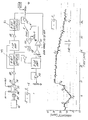
- the instrumentation for deriving voltage equivalents of the absorbance values is shown in Fig. 3 where a portion of Fig. 2 is repeated.
- the lamp 34 is a tungsten-halogen lamp focused on the flow cell 32; the power source for the lamp is identified at 46.
- the detector 36 and its filter 38 transform the absorbance to voltage passed through a voltage follower 48.
- V 1 The voltage of the Blank (V 1 ) is delivered to an 8-bit ADC/DAC Latch (1) (49) and stored there until needed.
- the voltage value of the Sample (V 2 ) is shunted around the latch (49) and is received by a log ratio amplifier 1-LR AMP where it is ratioed with the voltage value of the Blank released from storage in the cycle in which the ratio is to be made.
- the significant voltage output of 1-LR AMP is proportional to transmitted to a second 8-bit storage latch ADC/DAC Latch (2) (51) via a voltage follower 50.
- the output voltage (the log ratio voltage Blank:Sample) is transformed to a digital readout displayed at a monitoring panel DPM and is also sent through a voltage follower 52 producing voltage output A' which is delivered to a comparator 54 where signal A' is compared to the standard or theoretical voltage representing par performance.
- the comparator passes a voltage signal to the controller C of the pump P which doses the system with the proportioned amount of treating agent:tracer.
- Voltage output A' may be abbreviated standing for a signal to the comparator proportioned to the vanadate absorbance reading, equivalent to the concentration of the treating agent to be compared to the standard.
- determination of the vanadate concentration tells if the treating agent is being consumed within the range deemed theoretically sufficient to improve the quality of the system water by neutralizing the impurities.
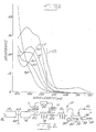
- Fig. 4 is an actual print-out of the performance of the vanadate tracer, deemed to exhibit normal performance of the treating agent at about 0.4 to 0.5 ppm.
- the system equilibrated (t i ) at about 0.45 ppm.
- the pump was turned off, whereupon the vanadate gradually declined in concentration to about 0.25 ppm at t 2 .
- the pump was restarted to re-establish the norm or par value, t 3 , enduring about 1 hour.
- monitoring of the level (consumption) of the treating agent may show substantially more or less than the expected rate, or substantial remnant metal stress, either circumstance placing a demand on the pump controller as a result of voltage comparisons.
- the demands on the pump controller can also be explained and expanded in terms of empirical stress equations.
- the desired product (treating agent) dosage can be represented by the equation,
Landscapes
- Health & Medical Sciences (AREA)
- Life Sciences & Earth Sciences (AREA)
- Chemical & Material Sciences (AREA)
- Biochemistry (AREA)
- General Physics & Mathematics (AREA)
- Medicinal Chemistry (AREA)
- Physics & Mathematics (AREA)
- Analytical Chemistry (AREA)
- Engineering & Computer Science (AREA)
- General Health & Medical Sciences (AREA)
- Food Science & Technology (AREA)
- Immunology (AREA)
- Pathology (AREA)
- Investigating Or Analyzing Non-Biological Materials By The Use Of Chemical Means (AREA)
- Investigating Or Analysing Materials By The Use Of Chemical Reactions (AREA)
- Investigating Or Analysing Materials By Optical Means (AREA)
- Water Treatment By Sorption (AREA)
- Separation Of Suspended Particles By Flocculating Agents (AREA)
Claims (9)
Applications Claiming Priority (2)
| Application Number | Priority Date | Filing Date | Title |
|---|---|---|---|
| US07/497,681 US5006311A (en) | 1990-03-23 | 1990-03-23 | Monitoring performance of a treating agent added to a body of water |
| US497681 | 1990-03-23 |
Publications (3)
| Publication Number | Publication Date |
|---|---|
| EP0447721A2 EP0447721A2 (de) | 1991-09-25 |
| EP0447721A3 EP0447721A3 (en) | 1992-04-22 |
| EP0447721B1 true EP0447721B1 (de) | 1995-08-23 |
Family
ID=23977875
Family Applications (1)
| Application Number | Title | Priority Date | Filing Date |
|---|---|---|---|
| EP90313932A Expired - Lifetime EP0447721B1 (de) | 1990-03-23 | 1990-12-19 | Überwachung der Funktion eines zu einer Wassermenge zugesetzten Behandlungsmittels und Analysiervorrichtung dafür |
Country Status (7)
| Country | Link |
|---|---|
| US (1) | US5006311A (de) |
| EP (1) | EP0447721B1 (de) |
| AT (1) | ATE126889T1 (de) |
| AU (1) | AU643498B2 (de) |
| CA (1) | CA2021892C (de) |
| DE (1) | DE69021860T2 (de) |
| ES (1) | ES2078323T3 (de) |
Families Citing this family (32)
| Publication number | Priority date | Publication date | Assignee | Title |
|---|---|---|---|---|
| US5242602A (en) * | 1992-03-04 | 1993-09-07 | W. R. Grace & Co.-Conn. | Spectrophotometric monitoring of multiple water treatment performance indicators using chemometrics |
| US5282379A (en) * | 1992-04-03 | 1994-02-01 | Nalco Chemical Company | Volatile tracers for diagnostic use in steam generating systems |
| US5266493A (en) * | 1993-01-22 | 1993-11-30 | Nalco Chemical Company | Monitoring boric acid in fluid systems |
| NZ250956A (en) * | 1993-03-03 | 1995-04-27 | Grace W R & Co | Monitoring concentrations of water treatment compositions using absorbance or emission spectra |
| US5320967A (en) * | 1993-04-20 | 1994-06-14 | Nalco Chemical Company | Boiler system leak detection |
| EP0640747B1 (de) * | 1993-08-20 | 1997-03-19 | Nalco Chemical Company | System zur Regelung eines Kessels nach einem PH/phosphat-Programm |
| US5411889A (en) * | 1994-02-14 | 1995-05-02 | Nalco Chemical Company | Regulating water treatment agent dosage based on operational system stresses |
| US5435969A (en) * | 1994-03-29 | 1995-07-25 | Nalco Chemical Company | Monitoring water treatment agent in-system concentration and regulating dosage |
| CN1069162C (zh) * | 1994-05-02 | 2001-08-08 | 诺尔科化学公司 | 用作改进的抗微生物剂的荧光杀生物剂组合物 |
| US5646338A (en) * | 1994-07-20 | 1997-07-08 | Betzdearborn Inc. | Deposition sensing method and apparatus |
| US5663489A (en) * | 1994-11-14 | 1997-09-02 | Betzdearborn Inc. | Methods and apparatus for monitoring water process equipment |
| US5565619A (en) * | 1994-11-14 | 1996-10-15 | Betz Laboratories, Inc. | Methods and apparatus for monitoring water process equipment |
| US5919707A (en) * | 1994-12-22 | 1999-07-06 | Nalco Chemical Company | Monitoring of rolling oil emulsions |
| DE69606378T2 (de) | 1995-11-09 | 2000-07-06 | Nalco Chemical Co., Naperville | Überwachung der mikrobiologischen Aktivität in einem Flüssigkeitssystem |
| US5658798A (en) * | 1996-02-08 | 1997-08-19 | Nalco Chemical Company | Detection of process components in food process streams by fluorescence |
| US5736405A (en) * | 1996-03-21 | 1998-04-07 | Nalco Chemical Company | Monitoring boiler internal treatment with fluorescent-tagged polymers |
| US5902749A (en) * | 1997-09-18 | 1999-05-11 | The United States Of America As Represented By The Secretary Of The Interior | Automated chemical metering system and method |
| US6068012A (en) | 1998-12-29 | 2000-05-30 | Ashland, Inc. | Performance-based control system |
| US6358746B1 (en) | 1999-11-08 | 2002-03-19 | Nalco Chemical Company | Fluorescent compounds for use in industrial water systems |
| US6472219B1 (en) | 2000-08-31 | 2002-10-29 | Ondeo Nalco Company | Use of tracers to monitor application of treatment products to cut flowers |
| US6662636B2 (en) | 2001-12-13 | 2003-12-16 | Ondeo Nalco Company | Method of reducing fouling in filters for industrial water system analytical devices |
| US6790666B2 (en) * | 2001-12-28 | 2004-09-14 | Nalco Company | Method to ascertain whether soluble hardness is calcium or magnesium based |
| US6790664B2 (en) * | 2001-12-28 | 2004-09-14 | Nalco Company | Fluorometric monitoring and control of soluble hardness of water used in industrial water systems |
| US7220382B2 (en) * | 2003-07-31 | 2007-05-22 | Nalco Company | Use of disulfonated anthracenes as inert fluorescent tracers |
| US20050025660A1 (en) * | 2003-07-31 | 2005-02-03 | Hoots John E. | Method of tracing corrosive materials |
| US9017649B2 (en) * | 2006-03-27 | 2015-04-28 | Nalco Company | Method of stabilizing silica-containing anionic microparticles in hard water |
| US8621911B2 (en) * | 2010-05-14 | 2014-01-07 | William J. McFaul | Method and system for determining levels of gases |
| US9134238B2 (en) * | 2010-12-01 | 2015-09-15 | Nalco Company | Method for determination of system parameters for reducing crude unit corrosion |
| US9266797B2 (en) | 2013-02-12 | 2016-02-23 | Ecolab Usa Inc. | Online monitoring of polymerization inhibitors for control of undesirable polymerization |
| US9399622B2 (en) | 2013-12-03 | 2016-07-26 | Ecolab Usa Inc. | Nitroxide hydroxylamine and phenylenediamine combinations as polymerization inhibitors for ethylenically unsaturated monomer processes |
| FI128387B (fi) * | 2018-05-11 | 2020-04-15 | Varo Teollisuuspalvelut Oy | Soodakattilavuodon toteaminen |
| CN118150780B (zh) * | 2024-05-11 | 2024-08-09 | 南京顺水达环保科技有限公司 | 一种多元胺炉水节能处理剂的综合性能检测方法 |
Family Cites Families (12)
| Publication number | Priority date | Publication date | Assignee | Title |
|---|---|---|---|---|
| GB320086A (en) * | 1928-07-03 | 1929-10-03 | Siemens Brothers & Co Ltd | Improvements relating to telephone instruments |
| GB1053184A (de) * | 1964-02-03 | |||
| CH522222A (de) * | 1967-03-10 | 1972-06-15 | Merck Patent Gmbh | Verfahren zur Bestimmung von Wasserstoffperoxid und Mittel zur Durchführung des Verfahrens |
| US3605775A (en) * | 1969-11-18 | 1971-09-20 | Gen Am Transport | Method to control dosage of additive into treatment process and automatic device therefor |
| DE2219552A1 (de) * | 1972-04-21 | 1973-11-08 | Bodenseewerk Perkin Elmer Co | Photometrisches analysenverfahren |
| US4217544A (en) * | 1978-10-16 | 1980-08-12 | Shell Oil Company | Method and apparatus for improved temperature compensation in a corrosion measurement system |
| US4478941A (en) * | 1982-11-26 | 1984-10-23 | The Dow Chemical Company | Method for determining component ratios employed to prepare polymers |
| US4659676A (en) * | 1985-04-17 | 1987-04-21 | Rhyne Jr Richard H | Fluorescent tracers for hydrophobic fluids |
| US4820647A (en) * | 1986-12-03 | 1989-04-11 | Biotrack, Inc. | Method for detecting a metal ion in an aqueous environment |
| US4783314A (en) * | 1987-02-26 | 1988-11-08 | Nalco Chemical Company | Fluorescent tracers - chemical treatment monitors |
| US4992380A (en) * | 1988-10-14 | 1991-02-12 | Nalco Chemical Company | Continuous on-stream monitoring of cooling tower water |
| US4966711A (en) * | 1989-02-27 | 1990-10-30 | Nalco Chemical Company | Transition metals as treatment chemical tracers |
-
1990
- 1990-03-23 US US07/497,681 patent/US5006311A/en not_active Expired - Fee Related
- 1990-07-24 CA CA002021892A patent/CA2021892C/en not_active Expired - Fee Related
- 1990-12-19 DE DE69021860T patent/DE69021860T2/de not_active Expired - Fee Related
- 1990-12-19 AT AT90313932T patent/ATE126889T1/de not_active IP Right Cessation
- 1990-12-19 EP EP90313932A patent/EP0447721B1/de not_active Expired - Lifetime
- 1990-12-19 ES ES90313932T patent/ES2078323T3/es not_active Expired - Lifetime
-
1991
- 1991-02-06 AU AU70815/91A patent/AU643498B2/en not_active Ceased
Also Published As
| Publication number | Publication date |
|---|---|
| CA2021892A1 (en) | 1991-09-24 |
| ES2078323T3 (es) | 1995-12-16 |
| ATE126889T1 (de) | 1995-09-15 |
| EP0447721A3 (en) | 1992-04-22 |
| CA2021892C (en) | 2001-04-03 |
| DE69021860T2 (de) | 1996-03-21 |
| US5006311A (en) | 1991-04-09 |
| AU7081591A (en) | 1991-10-03 |
| AU643498B2 (en) | 1993-11-18 |
| DE69021860D1 (de) | 1995-09-28 |
| EP0447721A2 (de) | 1991-09-25 |
Similar Documents
| Publication | Publication Date | Title |
|---|---|---|
| EP0447721B1 (de) | Überwachung der Funktion eines zu einer Wassermenge zugesetzten Behandlungsmittels und Analysiervorrichtung dafür | |
| US5132096A (en) | Monitoring performance of a water treating agent by measuring and resolving optical voltage analogs | |
| CA1334772C (en) | Continuous on-stream monitoring of cooling tower water | |
| Anderson et al. | Determination of bicarbonate and total volatile acid concentration in anaerobic digesters using a simple titration | |
| US8065906B2 (en) | Detection of free chlorine in water | |
| Hare | [1] Subnanomole-range amino acid analysis | |
| US6620315B2 (en) | System for optimized control of multiple oxidizer feedstreams | |
| US5236845A (en) | On-line iron (II) concentration monitoring to continuously determine corrosion in boiler systems | |
| US4379848A (en) | Method of analyzing an aqueous liquid for hexacyanoferrates | |
| Chiou et al. | Modified indigo method for gaseous and aqueous ozone analyses | |
| Granstrom et al. | Generation and use of chlorine dioxide in water treatment | |
| EP0486156A2 (de) | Einspritzströmungsanalyse von gesamt-anorganischem Phosphat | |
| US5300442A (en) | Method and device for measuring chlorine concentrations with enhanced sensitivity | |
| AU635144B2 (en) | On-line iron (ii) concentration monitoring to continuously determine corrosion in boiler systems | |
| EP0830598B1 (de) | Verfahren zum bestimmen des chemischen sauerstoffbedarfs, bei dem mangan iii verwendet wird | |
| Matuszewski et al. | Selective flow-injection determination of residual chlorine at low levels by amperometric detection with two polarized platinum electrodes | |
| Miller et al. | Automated iodometric method for determination of trace chlorate ion using flow injection analysis | |
| Dolinšek et al. | Application of the carbon cup atomisation technique in water analysis by atomic-absorption spectroscopy | |
| US6146896A (en) | Method and apparatus for measuring the nitrification effectiveness of activated sludge | |
| Gordon et al. | —Review Paper—Current State-Of-The-Art Measurements Of Ozone In The Gas Phase And In Solution | |
| JPH07294509A (ja) | 混合酸の分析方法および酸洗液の管理方法 | |
| GB1569026A (en) | Method and instrument for amperometric measurement of the free chlorine content in a solution | |
| US3433670A (en) | Pickling bath control apparatus and method | |
| US4278507A (en) | Method for amperometric measurement of the free-chlorine content in a solution | |
| US3656908A (en) | Method of determining the chromium content of aqueous mediums |
Legal Events
| Date | Code | Title | Description |
|---|---|---|---|
| PUAI | Public reference made under article 153(3) epc to a published international application that has entered the european phase |
Free format text: ORIGINAL CODE: 0009012 |
|
| 17P | Request for examination filed |
Effective date: 19901228 |
|
| AK | Designated contracting states |
Kind code of ref document: A2 Designated state(s): AT BE CH DE DK ES FR GB GR IT LI LU NL SE |
|
| PUAL | Search report despatched |
Free format text: ORIGINAL CODE: 0009013 |
|
| AK | Designated contracting states |
Kind code of ref document: A3 Designated state(s): AT BE CH DE DK ES FR GB GR IT LI LU NL SE |
|
| 17Q | First examination report despatched |
Effective date: 19931209 |
|
| GRAA | (expected) grant |
Free format text: ORIGINAL CODE: 0009210 |
|
| AK | Designated contracting states |
Kind code of ref document: B1 Designated state(s): AT BE CH DE DK ES FR GB GR IT LI LU NL SE |
|
| PG25 | Lapsed in a contracting state [announced via postgrant information from national office to epo] |
Ref country code: NL Free format text: LAPSE BECAUSE OF NON-PAYMENT OF DUE FEES Effective date: 19950823 Ref country code: GR Free format text: LAPSE BECAUSE OF FAILURE TO SUBMIT A TRANSLATION OF THE DESCRIPTION OR TO PAY THE FEE WITHIN THE PRESCRIBED TIME-LIMIT Effective date: 19950823 Ref country code: DK Effective date: 19950823 Ref country code: BE Effective date: 19950823 Ref country code: AT Effective date: 19950823 |
|
| REF | Corresponds to: |
Ref document number: 126889 Country of ref document: AT Date of ref document: 19950915 Kind code of ref document: T |
|
| REF | Corresponds to: |
Ref document number: 69021860 Country of ref document: DE Date of ref document: 19950928 |
|
| ITF | It: translation for a ep patent filed | ||
| REG | Reference to a national code |
Ref country code: CH Ref legal event code: PL |
|
| PG25 | Lapsed in a contracting state [announced via postgrant information from national office to epo] |
Ref country code: SE Effective date: 19951123 |
|
| REG | Reference to a national code |
Ref country code: ES Ref legal event code: FG2A Ref document number: 2078323 Country of ref document: ES Kind code of ref document: T3 |
|
| ET | Fr: translation filed | ||
| PGFP | Annual fee paid to national office [announced via postgrant information from national office to epo] |
Ref country code: CH Payment date: 19951231 Year of fee payment: 6 |
|
| NLV1 | Nl: lapsed or annulled due to failure to fulfill the requirements of art. 29p and 29m of the patents act | ||
| PLBE | No opposition filed within time limit |
Free format text: ORIGINAL CODE: 0009261 |
|
| STAA | Information on the status of an ep patent application or granted ep patent |
Free format text: STATUS: NO OPPOSITION FILED WITHIN TIME LIMIT |
|
| 26N | No opposition filed | ||
| PGFP | Annual fee paid to national office [announced via postgrant information from national office to epo] |
Ref country code: LU Payment date: 19961101 Year of fee payment: 7 |
|
| PG25 | Lapsed in a contracting state [announced via postgrant information from national office to epo] |
Ref country code: LI Free format text: LAPSE BECAUSE OF FAILURE TO SUBMIT A TRANSLATION OF THE DESCRIPTION OR TO PAY THE FEE WITHIN THE PRESCRIBED TIME-LIMIT Effective date: 19961231 Ref country code: CH Free format text: LAPSE BECAUSE OF FAILURE TO SUBMIT A TRANSLATION OF THE DESCRIPTION OR TO PAY THE FEE WITHIN THE PRESCRIBED TIME-LIMIT Effective date: 19961231 |
|
| PG25 | Lapsed in a contracting state [announced via postgrant information from national office to epo] |
Ref country code: LU Free format text: LAPSE BECAUSE OF NON-PAYMENT OF DUE FEES Effective date: 19971219 |
|
| PGFP | Annual fee paid to national office [announced via postgrant information from national office to epo] |
Ref country code: FR Payment date: 20011130 Year of fee payment: 12 |
|
| PGFP | Annual fee paid to national office [announced via postgrant information from national office to epo] |
Ref country code: GB Payment date: 20011204 Year of fee payment: 12 Ref country code: DE Payment date: 20011204 Year of fee payment: 12 |
|
| REG | Reference to a national code |
Ref country code: GB Ref legal event code: IF02 |
|
| PGFP | Annual fee paid to national office [announced via postgrant information from national office to epo] |
Ref country code: ES Payment date: 20020109 Year of fee payment: 12 |
|
| PG25 | Lapsed in a contracting state [announced via postgrant information from national office to epo] |
Ref country code: GB Free format text: LAPSE BECAUSE OF NON-PAYMENT OF DUE FEES Effective date: 20021219 |
|
| PG25 | Lapsed in a contracting state [announced via postgrant information from national office to epo] |
Ref country code: ES Free format text: LAPSE BECAUSE OF NON-PAYMENT OF DUE FEES Effective date: 20021220 |
|
| PG25 | Lapsed in a contracting state [announced via postgrant information from national office to epo] |
Ref country code: DE Free format text: LAPSE BECAUSE OF NON-PAYMENT OF DUE FEES Effective date: 20030701 |
|
| GBPC | Gb: european patent ceased through non-payment of renewal fee |
Effective date: 20021219 |
|
| PG25 | Lapsed in a contracting state [announced via postgrant information from national office to epo] |
Ref country code: FR Free format text: LAPSE BECAUSE OF NON-PAYMENT OF DUE FEES Effective date: 20030901 |
|
| REG | Reference to a national code |
Ref country code: FR Ref legal event code: ST |
|
| REG | Reference to a national code |
Ref country code: ES Ref legal event code: FD2A Effective date: 20021220 |
|
| PG25 | Lapsed in a contracting state [announced via postgrant information from national office to epo] |
Ref country code: IT Free format text: LAPSE BECAUSE OF NON-PAYMENT OF DUE FEES Effective date: 20051219 |