EP0447573B1 - Buse pour canal chaud - Google Patents
Buse pour canal chaud Download PDFInfo
- Publication number
- EP0447573B1 EP0447573B1 EP90105053A EP90105053A EP0447573B1 EP 0447573 B1 EP0447573 B1 EP 0447573B1 EP 90105053 A EP90105053 A EP 90105053A EP 90105053 A EP90105053 A EP 90105053A EP 0447573 B1 EP0447573 B1 EP 0447573B1
- Authority
- EP
- European Patent Office
- Prior art keywords
- hot runner
- nozzle body
- conducting
- mount
- runner nozzle
- Prior art date
- Legal status (The legal status is an assumption and is not a legal conclusion. Google has not performed a legal analysis and makes no representation as to the accuracy of the status listed.)
- Expired - Lifetime
Links
- 238000001746 injection moulding Methods 0.000 claims description 2
- 238000002347 injection Methods 0.000 abstract description 6
- 239000007924 injection Substances 0.000 abstract description 6
- 238000009434 installation Methods 0.000 abstract description 2
- 239000002826 coolant Substances 0.000 abstract 1
- 239000000463 material Substances 0.000 description 6
- 238000012423 maintenance Methods 0.000 description 3
- 238000005507 spraying Methods 0.000 description 3
- 238000010438 heat treatment Methods 0.000 description 2
- 239000000155 melt Substances 0.000 description 2
- 230000008439 repair process Effects 0.000 description 2
- 238000007789 sealing Methods 0.000 description 2
- 125000006850 spacer group Chemical group 0.000 description 2
- 230000009286 beneficial effect Effects 0.000 description 1
- 230000015572 biosynthetic process Effects 0.000 description 1
- 238000010276 construction Methods 0.000 description 1
- 230000007547 defect Effects 0.000 description 1
- 238000005485 electric heating Methods 0.000 description 1
- 238000010304 firing Methods 0.000 description 1
- 230000009969 flowable effect Effects 0.000 description 1
- 239000012530 fluid Substances 0.000 description 1
- 230000008014 freezing Effects 0.000 description 1
- 238000007710 freezing Methods 0.000 description 1
- 238000009413 insulation Methods 0.000 description 1
- 238000004519 manufacturing process Methods 0.000 description 1
- 238000000034 method Methods 0.000 description 1
- 239000000203 mixture Substances 0.000 description 1
- 238000007639 printing Methods 0.000 description 1
- 230000000284 resting effect Effects 0.000 description 1
Images
Classifications
-
- B—PERFORMING OPERATIONS; TRANSPORTING
- B29—WORKING OF PLASTICS; WORKING OF SUBSTANCES IN A PLASTIC STATE IN GENERAL
- B29C—SHAPING OR JOINING OF PLASTICS; SHAPING OF MATERIAL IN A PLASTIC STATE, NOT OTHERWISE PROVIDED FOR; AFTER-TREATMENT OF THE SHAPED PRODUCTS, e.g. REPAIRING
- B29C45/00—Injection moulding, i.e. forcing the required volume of moulding material through a nozzle into a closed mould; Apparatus therefor
- B29C45/17—Component parts, details or accessories; Auxiliary operations
- B29C45/26—Moulds
- B29C45/27—Sprue channels ; Runner channels or runner nozzles
- B29C45/28—Closure devices therefor
- B29C45/2806—Closure devices therefor consisting of needle valve systems
-
- B—PERFORMING OPERATIONS; TRANSPORTING
- B29—WORKING OF PLASTICS; WORKING OF SUBSTANCES IN A PLASTIC STATE IN GENERAL
- B29C—SHAPING OR JOINING OF PLASTICS; SHAPING OF MATERIAL IN A PLASTIC STATE, NOT OTHERWISE PROVIDED FOR; AFTER-TREATMENT OF THE SHAPED PRODUCTS, e.g. REPAIRING
- B29C45/00—Injection moulding, i.e. forcing the required volume of moulding material through a nozzle into a closed mould; Apparatus therefor
- B29C45/17—Component parts, details or accessories; Auxiliary operations
- B29C45/26—Moulds
- B29C45/27—Sprue channels ; Runner channels or runner nozzles
- B29C45/2735—Sprue channels ; Runner channels or runner nozzles for non-coaxial gates, e.g. for edge gates
-
- B—PERFORMING OPERATIONS; TRANSPORTING
- B29—WORKING OF PLASTICS; WORKING OF SUBSTANCES IN A PLASTIC STATE IN GENERAL
- B29C—SHAPING OR JOINING OF PLASTICS; SHAPING OF MATERIAL IN A PLASTIC STATE, NOT OTHERWISE PROVIDED FOR; AFTER-TREATMENT OF THE SHAPED PRODUCTS, e.g. REPAIRING
- B29C45/00—Injection moulding, i.e. forcing the required volume of moulding material through a nozzle into a closed mould; Apparatus therefor
- B29C45/17—Component parts, details or accessories; Auxiliary operations
- B29C45/26—Moulds
- B29C45/27—Sprue channels ; Runner channels or runner nozzles
- B29C45/30—Flow control means disposed within the sprue channel, e.g. "torpedo" construction
Definitions
- the present invention relates to a hot runner nozzle according to the preamble of claim 1.
- DE-A-3 417 220 discloses hot runner arrangements with a plurality of radial ducts on tongue-shaped nozzle tips in order to introduce a melt into a mold cavity or into a number of mold nests simultaneously via a plurality of injection openings.
- the disadvantage here is large heat losses, which are caused by the hot tips resting on or in the cooled mold plate.
- Narrow temperature ranges are generally necessary for injection molding, otherwise thread formation or freezing of the sprue occurs. If the melt temperature is too low, the sprue is too long and cold. Then you have problems such as printing an expiry date, e.g. B. on a cup bottom, or there are bumps, so that for example a cup can no longer be placed well. The sprue area on the product is extremely prone to breakage and is a frequent reason for complaints.
- EP-A-0 186 413 provides a hot runner system of the type mentioned at the outset, the nozzle body having obliquely downwardly directed tips at the bottom which are directly heated in a heat-conducting manner by an electric heating element arranged in the interior of the nozzle body. Melt, which each flow through an outer and an inner channel in parallel, are to be kept fluid until they mix at the outlet, namely at the lateral injection openings of the mold cavity. In an undercut shaped sleeve which surrounds the nozzle body at a radial distance, the substantially cylindrical guide tips are attached to its lower end in such a way that a desired radial projection can be set through a small hole from below.
- this can only be done by a toolmaker and only during installation; after material has been injected, removal and maintenance are almost impossible.
- the aim of the invention is to overcome the disadvantages of the prior art with simple means and to further develop a device of the type mentioned in such a way that multiple gating can be carried out economically, even at larger gates, with good mounting options and regardless of the type of one hot runner system to be used later.
- the invention provides according to claim 1 that the holder is provided with a locking ring for the guide tips, which can be fixed and detached is attached to a carrier via a spacer ring or basket with poorly heat-conducting webs.
- the clamping ring can be fixed by means of at least one pressure screw, the setting is carried out quickly and precisely, especially since suitable locking means can be arranged on the clamping ring and / or on the guide tips.
- a recess can be provided on the holder as a centering means, into which an associated guide tip collar projects.
- the guide tips sitting in the holder can be fixed in position by inserting the nozzle body, in particular by form-fitting the attachment with a rear stop of the guide tips.
- these can be essentially cylindrical and have a conical end, the opening angle of which is smaller than that of a dome-shaped inlet cone, in which the extended guide tip extends right up to the mold cavity. In this way, accurate and reliable centering is achieved.
- the cavity plate according to claim 7 for receiving the carrier has a hole which can be locked at the bottom by a floor, so that easy access can be opened and closed.
- the holder in the cavity plate from a hole in particular optionally from one or from the other direction (up or down) can be installed or removed. It is advantageous if, according to claim 8, the connection head comes to rest on a shoulder of the bore, thereby ensuring exact positioning.
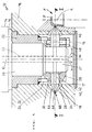
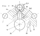
- FIGS. 1 and 2 The embodiment of a hot runner nozzle according to the invention shown in FIGS. 1 and 2 is generally designated 10. It has a connection head 14, which is inserted into a bore 17 of a cavity plate 18 and comes to rest with a shoulder 16 thereon, furthermore a nozzle body 26, which is essentially rotationally symmetrical about an axis 12 and held in a carrier 32 designed here as a bushing is. A central main channel 22 extends through the nozzle body 26 to the lower end of an extension 27.
- a bracket 30 surrounds the neck 27 concentrically. It is fastened to the carrier 32 by means of a poorly heat-conducting spacer ring or basket 34 which has webs 36 arranged at circumferential intervals.
- guide tips 28 are held by a clamping ring 38 which, for. B. can be fixed by means of at least one pressure screw 48 on the holder 30 and thereby clamps the guide tips 28 in the set radial position.
- a recess 40 in the holding elements 30, 38 can cooperate with a collar 42 on the guide tips 28 as a stop.
- the latter extend right up to the sprue end of the inlet cone 44, to which the mold cavity F connects.
- the bore 17 of the cavity plate 18 is closed at the bottom by a bottom 19.
- the material to be processed flows out of the main channel 22 in the direction of arrow M; it is deflected from the bottom 19 to the inlet cones 44, where the guide tips 28 bring about additional heating.
- the readily flowable material therefore passes through an annular gap 68 into the mold cavity F, which contains a suitable mold core K.
- side channels 24 branch off from the main channel 22 in the projection 27 of the nozzle body 26, as indicated by dotted lines in FIG. 1. They extend to the ends of the guide tips 28, which each form a cone 66. If it is withdrawn, material to be processed can exit through the annular gap 68. During the spraying process, it flows through the side channels 24 into the inlet cone 44 and thus into the mold cavity F.
- the arrangement is suitable for both single spraying and multiple spraying, in particular also for articles which have a greater thickness on the wall side in the mold cavity. Since the guide tips 28 can have a selectable inclination to the axis 12, any types of gating are possible.
- a nozzle body 26 which is penetrated by a heatable main channel 22 and which at its lower end 27 has good heat-conducting, displaceable and lockable guide tips with respect to the mold cavity F. 28 has. These can be removed from a heat-conducting holder 30 or arranged to be retractable into its interior, which can be attached to a cylindrical extension 27 of the nozzle body 26 or before it is installed on the mold cavity plate 18.
- the leading tips 28, which terminate with a cone 66, are transverse or inclined to the axis 12 of the nozzle body 26. When the position is withdrawn in the main channel 22 and / or in the side channels 24, they release an injection annular gap 68, which can be partially or completely moved by advancing the cone 66 in question is lockable.
Landscapes
- Engineering & Computer Science (AREA)
- Manufacturing & Machinery (AREA)
- Mechanical Engineering (AREA)
- Moulds For Moulding Plastics Or The Like (AREA)
- Percussion Or Vibration Massage (AREA)
- Injection Moulding Of Plastics Or The Like (AREA)
Claims (8)
- Buse pour canal chaud (10) pour dispositifs d'injection, avec une tête de raccordement (14) qui est fixable à une plaque d'empreinte du moule (18) et sur laquelle est situé un corps de buse (26) traversé par un canal principal (22) chauffable pour la masse de matière plastique à injecter, ce corps de buse étant pourvu, selon les besoins, d'aiguilles d'obturation dans le canal principal et / ou dans des canaux latéraux conduisant à la plaque d'empreinte du moule (18), le corps de buse (26) possédant à ou près de son extrêmité inférieure (27) des pointes de conduite (28) conduisant bien la chaleur, situées sur une fixation (30) conduisant également bien la chaleur, et coulissables et blocables par rapport à l'empreinte du moule (F), CARACTERISEE EN CE QUE la fixation (30) est pourvue d'un anneau de blocage (38) serrable et desserrable pour les pointes de conduite (28), lequel est fixé à un support (32) moyennant une bague ou panier d'écartement (34) avec des traverses mauvaises conductrices de la chaleur.
- Buse pour canal chaud selon la revendication 1, CARACTERISEE EN CE QUE le corps de buse (26) a substantiellement une forme à symétrie de révolution par rapport à un axe (12), et que la fixation (30) encercle concentriquement une embase cylindrique (27) du corps de buse (26).
- Buse pour canal chaud selon la revendication 1 ou 2, CARACTERISEE EN CE QUE l'anneau de blocage (38) est fixable par au moins une vis de serrage (48).
- Buse pour canal chaud selon l'une des revendications de 1 à 3, CARACTERISEE EN CE QU'un évidement (40) se trouve sur la fixation (30), en tant qu'élément de centrage, dans lequel va un collet correspondant (42) de la pointe de conduite.
- Buse pour canal chaud selon l'une des revendications de 1 à 4, CARACTERISEE EN CE QUE les pointes de conduite (28) logées dans la fixation (30, 38) peuvent être fixées dans leur position en poussant le corps de buse (26), notamment grâce à la solidarité de forme de l'embase (27) avec une butée dorsale (42) des pointes de conduite (28).
- Buse pour canal chaud selon l'une des revendications 1 à 5, CARACTERISEE EN CE QUE chaque pointe de conduite (28) a une partie principale de forme cylindrique et une extrêmité conique, dont l'angle d'ouverture est plus petit que celui d'un cône d'entrée en forme de calotte (44), dans lequel la pointe de conduite avancée (28) atteint directement l'empreinte du moule (F).
- Buse pour canal chaud selon l'une des revendications 1 à 6, CARACTERISEE EN CE QUE la plaque d'empreinte du moule (18) a une perforation (17) pour recevoir le support (32), cette perforation étant refermable en bas par un fond (19).
- Buse pour canal chaud selon la revendication 7, CARACTERISEE EN CE QUE la tête de raccordement (14) vient se poser sur un épaulement (16) de la perforation (17).
Priority Applications (5)
| Application Number | Priority Date | Filing Date | Title |
|---|---|---|---|
| EP90105053A EP0447573B1 (fr) | 1990-03-17 | 1990-03-17 | Buse pour canal chaud |
| ES90105053T ES2077596T3 (es) | 1990-03-17 | 1990-03-17 | Tobera de canales calientes. |
| DE59009475T DE59009475D1 (de) | 1990-03-17 | 1990-03-17 | Heisskanaldüse. |
| DE9003574U DE9003574U1 (de) | 1990-03-17 | 1990-03-17 | Heißkanaldüse |
| AT90105053T ATE125746T1 (de) | 1990-03-17 | 1990-03-17 | Heisskanaldüse. |
Applications Claiming Priority (1)
| Application Number | Priority Date | Filing Date | Title |
|---|---|---|---|
| EP90105053A EP0447573B1 (fr) | 1990-03-17 | 1990-03-17 | Buse pour canal chaud |
Publications (2)
| Publication Number | Publication Date |
|---|---|
| EP0447573A1 EP0447573A1 (fr) | 1991-09-25 |
| EP0447573B1 true EP0447573B1 (fr) | 1995-08-02 |
Family
ID=8203763
Family Applications (1)
| Application Number | Title | Priority Date | Filing Date |
|---|---|---|---|
| EP90105053A Expired - Lifetime EP0447573B1 (fr) | 1990-03-17 | 1990-03-17 | Buse pour canal chaud |
Country Status (4)
| Country | Link |
|---|---|
| EP (1) | EP0447573B1 (fr) |
| AT (1) | ATE125746T1 (fr) |
| DE (1) | DE59009475D1 (fr) |
| ES (1) | ES2077596T3 (fr) |
Cited By (2)
| Publication number | Priority date | Publication date | Assignee | Title |
|---|---|---|---|---|
| US7658606B2 (en) | 2006-12-22 | 2010-02-09 | Mold-Masters (2007) Limited | Edge gated injection molding apparatus |
| US7658605B2 (en) | 2006-12-29 | 2010-02-09 | Mold-Masters (2007) Limited | Edge gated injection molding apparatus |
Families Citing this family (12)
| Publication number | Priority date | Publication date | Assignee | Title |
|---|---|---|---|---|
| DE10231093C1 (de) * | 2002-07-10 | 2003-10-30 | Otto Maenner Heiskanalsysteme | Spritzgießdüse für Kunststoff mit wenigstens zwei Austrittsöffnungen |
| DE10345578A1 (de) * | 2003-09-29 | 2005-05-12 | Hans Schreck | Vorrichtung zum Anspritzen von insbesondere Kunststoffformteilen |
| DE102005050360B4 (de) | 2004-10-20 | 2015-11-05 | Mold-Masters (2007) Limited | Spritzgiessvorrichtung mit Seitenanguss |
| US7396226B2 (en) | 2006-03-10 | 2008-07-08 | Mold-Masters (2007) Limited | Nozzle sealing assembly |
| US7803306B2 (en) | 2006-06-16 | 2010-09-28 | Mold-Masters (2007) Limited | Individual cavity shut-off valve for an injection molding apparatus |
| CA2591729A1 (fr) | 2006-06-16 | 2007-12-16 | Mold-Masters Limited | Robinet d'arret de cavite distincte pour moule a injection |
| DE102008028577B4 (de) | 2007-06-20 | 2016-11-10 | Mold-Masters (2007) Limited | Eckenangussspritzgießvorrichtung |
| DE202008005073U1 (de) | 2008-04-11 | 2008-07-03 | EWIKON Heißkanalsysteme GmbH & Co. KG | Heißkanaldüse zur Seitenanspritzung |
| US7794228B2 (en) * | 2008-04-29 | 2010-09-14 | Mold-Masters (2007) Limited | Injection molding apparatus having an edge-gated runnerless nozzle |
| EP2243613A1 (fr) * | 2009-04-21 | 2010-10-27 | Hans Schreck | Dispositif de buses et procédé d'injection de pièces de formage en matière synthétique |
| DE202009004786U1 (de) | 2009-05-06 | 2010-09-23 | EWIKON Heißkanalsysteme GmbH & Co. KG | Heißkanaldüse zur Seitenanspritzung |
| US9174372B2 (en) | 2013-03-15 | 2015-11-03 | Sabic Global Technologies B.V. | Shut off nozzle system and methods for making and using the same |
Family Cites Families (3)
| Publication number | Priority date | Publication date | Assignee | Title |
|---|---|---|---|---|
| US4304544A (en) * | 1974-10-21 | 1981-12-08 | Fast Heat Element Mfg. Co., Inc. | Electrically heated nozzles and nozzle systems |
| GB8432451D0 (en) * | 1984-12-21 | 1985-02-06 | Tanner Ag | Injection moulding of plastics |
| DE3545002A1 (de) * | 1985-12-19 | 1987-07-02 | Reiss Int Gmbh | Verfahren zum spritzen von kunststoffteilen aus duroplasten |
-
1990
- 1990-03-17 DE DE59009475T patent/DE59009475D1/de not_active Expired - Fee Related
- 1990-03-17 ES ES90105053T patent/ES2077596T3/es not_active Expired - Lifetime
- 1990-03-17 AT AT90105053T patent/ATE125746T1/de not_active IP Right Cessation
- 1990-03-17 EP EP90105053A patent/EP0447573B1/fr not_active Expired - Lifetime
Cited By (2)
| Publication number | Priority date | Publication date | Assignee | Title |
|---|---|---|---|---|
| US7658606B2 (en) | 2006-12-22 | 2010-02-09 | Mold-Masters (2007) Limited | Edge gated injection molding apparatus |
| US7658605B2 (en) | 2006-12-29 | 2010-02-09 | Mold-Masters (2007) Limited | Edge gated injection molding apparatus |
Also Published As
| Publication number | Publication date |
|---|---|
| EP0447573A1 (fr) | 1991-09-25 |
| ES2077596T3 (es) | 1995-12-01 |
| ATE125746T1 (de) | 1995-08-15 |
| DE59009475D1 (de) | 1995-09-07 |
Similar Documents
| Publication | Publication Date | Title |
|---|---|---|
| EP0447573B1 (fr) | Buse pour canal chaud | |
| DE3403301C2 (fr) | ||
| DE2709609C2 (de) | Ventilgesteuertes Einlaßteil für Spritzgußwerkzeuge | |
| DE69008894T2 (de) | Spritzgusseinrichtung mit Gasdurchfluss durch die Ventilöffnung. | |
| DE69914509T2 (de) | Verfahren zur Herstellung einer dreiteiligen Spritzgiessdüse und eines Spritzgiesshohlraumeinsatzes und zum Kühlen eines Formhohlraumes | |
| CH693171A5 (de) | Verfahren und Vorrichtung zum Kühlen von kunststoffgeformten Gegenständen nach der Formung. | |
| DE69603538T2 (de) | Spritzgiessvorrichtung mit seitlichem Anschnitt mit radial montierten Anschnitteinsätzen | |
| WO2005018906A1 (fr) | Filiere de moulage par injection | |
| EP0962296A2 (fr) | Buse à fermeture à aiguille | |
| DE10354456A1 (de) | Heißläuferdüse mit einer Spitze, einem die Spitze umgebenden Teil und einem Positionierteil | |
| DE102004017276A1 (de) | Frontseitig montierbare Düse mit einem seitlichen Anguss | |
| DE3912209A1 (de) | Spritzgiesseinrichtung mit duesenverschlusssystem | |
| EP0528316B1 (fr) | Dispositif de moulage par injection avec buse à canal chaud | |
| DE9003574U1 (de) | Heißkanaldüse | |
| EP1603729B1 (fr) | Buse de vanne pointeau | |
| EP3398749A1 (fr) | Insert pour une buse de moulage par injection et buse de moulage par injection comprenant un tel insert | |
| WO1998019847A1 (fr) | Filiere de moulage par injection | |
| DE69217794T2 (de) | Spritzgiessvorrichtung mit Torpedo mit winklig angeordneter Spitze | |
| DE112006000474B4 (de) | Spritzgießvorrichtung | |
| EP0284920B1 (fr) | Canal de chauffage pour machines à injecter les matières plastiques | |
| EP2209601A2 (fr) | Buse de moulage par injection | |
| DE4132986C2 (de) | Düsenanordnung zum Spritzgießen von großflächigen Kunststoffteilen mit eingeschlossenen Hohlräumen | |
| WO2006084669A1 (fr) | Dispositif de moulage par injection | |
| DE19618957A1 (de) | Spritzguß-Seitenangußdichtung mit heißer Spitze und Umfangsrippe | |
| EP0321678B1 (fr) | Buse d'injection et dispositif de moulage d'injection |
Legal Events
| Date | Code | Title | Description |
|---|---|---|---|
| PUAI | Public reference made under article 153(3) epc to a published international application that has entered the european phase |
Free format text: ORIGINAL CODE: 0009012 |
|
| 17P | Request for examination filed |
Effective date: 19901220 |
|
| AK | Designated contracting states |
Kind code of ref document: A1 Designated state(s): AT BE CH DE DK ES FR GB GR IT LI LU NL SE |
|
| RBV | Designated contracting states (corrected) |
Designated state(s): AT BE DE ES FR GB NL |
|
| RAP1 | Party data changed (applicant data changed or rights of an application transferred) |
Owner name: DIPL.-ING. HERBERT GUENTHER GESELLSCHAFT MBH |
|
| 17Q | First examination report despatched |
Effective date: 19930226 |
|
| GRAA | (expected) grant |
Free format text: ORIGINAL CODE: 0009210 |
|
| AK | Designated contracting states |
Kind code of ref document: B1 Designated state(s): AT BE DE ES FR GB NL |
|
| REF | Corresponds to: |
Ref document number: 125746 Country of ref document: AT Date of ref document: 19950815 Kind code of ref document: T |
|
| REF | Corresponds to: |
Ref document number: 59009475 Country of ref document: DE Date of ref document: 19950907 |
|
| ET | Fr: translation filed | ||
| GBT | Gb: translation of ep patent filed (gb section 77(6)(a)/1977) |
Effective date: 19950908 |
|
| REG | Reference to a national code |
Ref country code: ES Ref legal event code: FG2A Ref document number: 2077596 Country of ref document: ES Kind code of ref document: T3 |
|
| PG25 | Lapsed in a contracting state [announced via postgrant information from national office to epo] |
Ref country code: GB Effective date: 19960317 Ref country code: AT Effective date: 19960317 |
|
| PG25 | Lapsed in a contracting state [announced via postgrant information from national office to epo] |
Ref country code: ES Free format text: LAPSE BECAUSE OF NON-PAYMENT OF DUE FEES Effective date: 19960318 |
|
| PG25 | Lapsed in a contracting state [announced via postgrant information from national office to epo] |
Ref country code: BE Effective date: 19960331 |
|
| PLBE | No opposition filed within time limit |
Free format text: ORIGINAL CODE: 0009261 |
|
| STAA | Information on the status of an ep patent application or granted ep patent |
Free format text: STATUS: NO OPPOSITION FILED WITHIN TIME LIMIT |
|
| 26N | No opposition filed | ||
| BERE | Be: lapsed |
Owner name: HERBERT GUNTHER G.M.B.H. Effective date: 19960331 |
|
| PG25 | Lapsed in a contracting state [announced via postgrant information from national office to epo] |
Ref country code: NL Effective date: 19961001 |
|
| GBPC | Gb: european patent ceased through non-payment of renewal fee |
Effective date: 19960317 |
|
| PG25 | Lapsed in a contracting state [announced via postgrant information from national office to epo] |
Ref country code: FR Effective date: 19961129 |
|
| NLV4 | Nl: lapsed or anulled due to non-payment of the annual fee |
Effective date: 19961001 |
|
| REG | Reference to a national code |
Ref country code: FR Ref legal event code: ST |
|
| PG25 | Lapsed in a contracting state [announced via postgrant information from national office to epo] |
Ref country code: DE Effective date: 19970902 |
|
| REG | Reference to a national code |
Ref country code: ES Ref legal event code: FD2A Effective date: 19990201 |