EP0447548B1 - Method of manufacturing a plastic graded-index optical transmission element - Google Patents
Method of manufacturing a plastic graded-index optical transmission element Download PDFInfo
- Publication number
- EP0447548B1 EP0447548B1 EP89910942A EP89910942A EP0447548B1 EP 0447548 B1 EP0447548 B1 EP 0447548B1 EP 89910942 A EP89910942 A EP 89910942A EP 89910942 A EP89910942 A EP 89910942A EP 0447548 B1 EP0447548 B1 EP 0447548B1
- Authority
- EP
- European Patent Office
- Prior art keywords
- optical transmission
- transmission element
- refractive index
- index distribution
- uncured
- Prior art date
- Legal status (The legal status is an assumption and is not a legal conclusion. Google has not performed a legal analysis and makes no representation as to the accuracy of the status listed.)
- Expired - Lifetime
Links
Images


Classifications
-
- G—PHYSICS
- G02—OPTICS
- G02B—OPTICAL ELEMENTS, SYSTEMS OR APPARATUS
- G02B6/00—Light guides; Structural details of arrangements comprising light guides and other optical elements, e.g. couplings
-
- G—PHYSICS
- G02—OPTICS
- G02B—OPTICAL ELEMENTS, SYSTEMS OR APPARATUS
- G02B3/00—Simple or compound lenses
- G02B3/0087—Simple or compound lenses with index gradient
-
- G—PHYSICS
- G02—OPTICS
- G02B—OPTICAL ELEMENTS, SYSTEMS OR APPARATUS
- G02B3/00—Simple or compound lenses
-
- B—PERFORMING OPERATIONS; TRANSPORTING
- B29—WORKING OF PLASTICS; WORKING OF SUBSTANCES IN A PLASTIC STATE IN GENERAL
- B29C—SHAPING OR JOINING OF PLASTICS; SHAPING OF MATERIAL IN A PLASTIC STATE, NOT OTHERWISE PROVIDED FOR; AFTER-TREATMENT OF THE SHAPED PRODUCTS, e.g. REPAIRING
- B29C48/00—Extrusion moulding, i.e. expressing the moulding material through a die or nozzle which imparts the desired form; Apparatus therefor
- B29C48/03—Extrusion moulding, i.e. expressing the moulding material through a die or nozzle which imparts the desired form; Apparatus therefor characterised by the shape of the extruded material at extrusion
- B29C48/05—Filamentary, e.g. strands
-
- G—PHYSICS
- G02—OPTICS
- G02B—OPTICAL ELEMENTS, SYSTEMS OR APPARATUS
- G02B6/00—Light guides; Structural details of arrangements comprising light guides and other optical elements, e.g. couplings
- G02B6/02—Optical fibres with cladding with or without a coating
- G02B6/02033—Core or cladding made from organic material, e.g. polymeric material
- G02B6/02038—Core or cladding made from organic material, e.g. polymeric material with core or cladding having graded refractive index
Definitions
- the present invention relates to a method of manufacturing an optical transmission element which is useful for optical transmission lines such as near parabolic optical fibers, rod-like convergent lenses, and photosensors.
- Optical transmission elements each with refractive indexes gradually distributed from the center toward the periphery on a cross-section thereof are disclosed in Japanese Examined Patent Publication No. 47-816, Japanese Examined Patent Publication No. 47-28059, and European Patent Application Publication No. 0208159.
- the graded-index optical transmission element disclosed in Japanese Examined Patent Publication No. 47-816 is made of glass and fabricated by an ion exchange method. This method has a poor productivity and cannot produce elements having an identical shape (an identical length, in particular) and an identical performance. Even with an identical performance, the fabricated graded-index optical transmission elements have uneven lengths, and thus problems arise with handling thereof.
- the plastic graded-index optical transmission element disclosed in Japanese Examined Patent Publication No. 47-28059 is made by mixing two or more transparent polymers having different refractive indexes and different solubilities with respect to a particular solvent.
- the mixed polymers are shaped into a rod or a fiber, and immersed in the solvent to extract a part of the polymers from the surface thereof, thereby changing a mixing ratio of the polymers from the surface toward the center thereof. Since the plastic graded-index optical transmission element of this method is made of a mixture of two or more polymers having different refractive indexes, fluctuations in the refractive indexes of the element occur deteriorating the transparency, and causing light scattering, and therefore, the element cannot serve as the graded-index optical transmission element. Accordingly, little improvement can be expected in the application and development of this method.
- European Patent Publication No. 0208159 describes a method in which (A) at least one kind of thermoplastic polymer and (B) a monomer which is compatible with the polymer (A) when polymerized and forms a polymer having a refractive index different from that of the polymer (A), are mixed and formed into a rod-like shape. From the surface of the shaped body, the monomer (B) is volatilized to continuously distribute the monomer (B) from the surface toward the interior of the formed article, and thereafter, the non-polymerized monomer in the shaped body is polymerized to form a plastic graded-index optical transmission element.
- the graded index optical transmission element fabricated according to the above-mentioned method provides a refractive index distribution curve " b " of Fig. 2.
- the curve b is relatively close to the ideal curve expressed by the equation (1).
- the refractive index distribution is greatly deviated from the ideal curve.
- the article When a grid pattern is observed through these optical transmission elements, if the optical transmission element has a refractive index pattern which almost correctly follows the quadratic curve defined by the equation (1), the article will provide a normal grid image as shown in Fig. 3(a). If, however, the refractive index distribution of the optical transmission element deviates from the ideal refractive index distribution, as indicated by (b) of Fig. 2, the element will provide a distorted grid image as shown in Figs. 3(b) and 3(c), since the element cannot transmit a incorrect image. In this case, a modulation transfer factor (MTF) indicating the resolution of the element is also very low, i.e., less than 30% which is not acceptable for use as an optical transmission element of a facsimile.
- MTF modulation transfer factor
- the conventional graded-index optical transmission element with the refractive index distribution as shown by (b) of Fig. 2 must be cut or eluted by a solvent process to remove a portion outer than the position (d) of Fig. 2, thereby providing the optical transmission element with an optical path having a relatively ideal refractive index distribution. It is, however, difficult to provide an optical transmission element with a high resolution, and thus the productivity thereof is very low, and it is very difficult to constantly produce elements having a uniform quality.
- An object of the invention is to provide a method of manufacturing a plastic graded-index optical transmission element which can be applied to a facsimile and an image sensor employing a monochromatic light source and has a high resolution and a less chromatic aberration.
- the refractive index distribution curve of the optical transmission element manufactured according to the invention must substantially approximate the ideal refractive index distribution curve ((a) of Fig. 1) expressed with the equation (1), at least in the range of 0.25r0 to 0.70r0 , preferably 0.20r0 to 0.75r0, from the center axis of the element.
- the plastic graded-index optical transmission element manufactured according to the invention involving the above-mentioned range which agrees with the ideal refractive index distribution defined by the equation (1) provides a nearly correct image of a grid observed with the optical transmission element, even if the refractive index distribution of the optical transmission element relatively deviates from the refractive index distribution curve defined by the equation (1) in the region ranging from the center axis to 0.25r0 or in the region outside 0.70r0.
- the plastic graded-index optical transmission element manufactured according to the invention must have a value n0 of 1.4 ⁇ n0 ⁇ 1.6. If the value exceeds 1.6, the optical transmission plastic element is difficult to produce, and if the value n0 is smaller than 1.4, the difference of refractive indexes at the center axis and at the periphery of the element cannot be enlarged, to thus realize an optical transmission element having an excellent resolution and image transmitting characteristics.
- the plastic graded-index optical transmission element manufactured according to the invention is used for a facsimile, etc.
- a plurality of such elements instead of a single element thereof are usually arranged in a single row or a plurality of rows in a zigzag manner, to form an array of the optical transmission elements in which images provided by the elements partly overlap each other to form an image.
- the visibility of the overlapped images depends on the degree of overlapping, which is influenced by the diameter of each optical transmission element.
- the radius r0 of the optical transmission element must be in the range of 0.4 to 0.6 mm. If the element is thinner than this, the element may have an insufficient brightness and be difficult to produce with a uniform refractive index distribution. If the element is thicker than the above range, the images provided by the array of the optical transmission elements may unevenly overlap each other, and thus will not transmit clear images.
- the MTF of the array over 40%, the array can transmit clearer and brighter images.
- the MTF which indicates resolution of the plastic graded-index optical transmission element of the invention can be determined as follows. Namely, as shown in Fig. 4, a light source 42, a filter 43, a diffusion plate 44, a grid 45, and an array 47 composed of a plurality of plastic graded-index optical transmission elements 41 form a resolution measuring apparatus. A grid image having a spatial frequency of 4 (line-pairs/mm) is passed through the optical transmission elements 41 to form an image on a CCD line sensor 46. The formed grid image is read, and the maximum value (i max ) and the minimum value (i min ) of light quantities of the image are measured as shown in Fig. 5.
- the MTF of the plastic graded-index optical transmission element of the invention must be not less than 55%. If the MTF is smaller than 55%, the optical transmission element provides a low resolution and cannot form a clear image when applied to a copying machine such as a facsimile.
- the plastic graded-index optical transmission element of the invention may be fabricated in the following manner:
- N (N ⁇ 3) uncured liquid substances each having a viscosity of between 103 and 108 poises in an uncured state and refractive indexes n of n1 > n2 > n3 ... n N in a cured state are prepared, and these uncured liquid substances are concentrically laminated, one upon the other, in such a way that the refractive indexes are successively reduced from the center toward the periphery of the laminated substances, thereby forming an uncured strand fiber.
- the substances of the strand fiber are then mutually diffused between adjacent layers to provide a continuous refractive index distribution between the layers, during which or thereafter the uncured strand fiber is cured.
- N must be 3 or greater than 3, preferably 3 to 7, and more preferably 3 to 5.
- each of the uncured liquid substances must have a viscosity between 103 and 108 poises and be curable. If the viscosity is smaller than 103 poises, the strand will be easily broken and hardly form a strand-like shape. If the viscosity is greater than 108 poises, the substance will have a poor processability which will lead to a deterioration of the concentricity or forming of irregular diameters.
- liquid substances to be employed when carrying out the invention may be radical polymerizable vinyl monomers, or compositions comprising the monomers and polymers that are soluble with the monomers.
- the uncured liquid substances are preferably composed of vinyl-based monomers and soluble polymers.
- the polymers to be used must have a good compatibility with polymers produced from the radical polymerizable vinyl monomers.
- polymers having an identical refractive index for respective layers because an optical transmission plastic element having refractive indexes continuously distributed from the center toward the surface of the element can be formed.
- poly(methyl methacrylate) has an excellent transparency and a high refractive index, and therefore, is preferably used for producing the plastic graded-index optical transmission elements in accordance with the invention.
- thermosetting catalyst and/or photocatalyst to the uncured substances.
- the fiber strand containing the thermosetting catalyst and/or photocatalyst is heated or irradiated with light, preferably ultraviolet light.
- the thermosetting catalyst may be a peroxide-based catalyst
- the photopolymerization catalyst may be benzophenone, benzoinalkylether, 4'-isopropyl-2-hydroxy-2-methyl-propiophenone, 1-hydroxycyclohexylphenylketone, benzylmethylketal, 2,2-diethoxyacetophenone, chlorothioxanthone, thioxanthone-based compounds, benzophenone-based compounds, 4-dimethylaminobenzoic ethyl, 4-dimethylaminobenzoic isoamyl, N-methyldiethanolamine, triethylamine, etc.
- the light source used for the photopolymerization may be a carbon arc lamp, a high-pressure mercury lamp, an ultra-high-pressure mercury lamp, a low-pressure mercury lamp, a chemical lamp, a xenon lamp, or a laser beam, etc., emitting light having a wavelength of 150 to 600 nm.
- a strand fiber forming apparatus shown in Fig. 6, for example may be used.
- a concentric composite nozzle 61 extrudes an uncured strand fiber 62, which is passed through a mutual diffusion portion 63 for mutually diffusing monomers of respective layers of the strand fiber to impart a refractive index distribution, as well as through a curing portion 64 for curing the uncured substances.
- the strand fiber is then passed between pulling rollers 65, and wound, as a plastic graded-index optical transmission element 66, around a winding portion 67.
- an inert gas such as nitrogen gas is introduced from an inert gas introducing port 68, and discharged from a discharging port 69.
- the lens properties were measured with an evaluation apparatus shown in Fig. 7.
- Each optical transmission element prepared according to the Examples was cut to a length of about one fourth ( ⁇ /4) of a period ( ⁇ ) of a light beam.
- the period ( ⁇ ) was determined from the wave form of a He-Ne laser beam passing through the element.
- the element was then polished with a polisher to make both end faces of the sample parallel to each other and orthogonal to a longitudinal axis, and thus a sample to be evaluated was obtained.
- a sample table (76) was placed on an optical bench (71), and a sample (78) to be evaluated was placed on the sample table (76).
- a diaphragm (74) was adjusted so that light from a light source (72) passes through a condenser lens (73), the diaphragm (74), and a glass plate (75) and entirely irradiates an end face of the sample.
- the sample (78) and a Polaroid camera (77) were adjusted so that the light was focused on a film in the Polaroid (a trademark of the Polaroid company) camera. An image of a square grid was photographed, and the distortion of the grid was observed.
- the glass plate (75) was a chrome-plated photomasking glass, the chrome film on which was precisely processed to form a square grid pattern of 0.1 mm.
- MEK methylethylketone
- the forming apparatus of Fig. 6 was provided with a concentric three-layer composite spinning nozzle.
- the three kinds of the original liquids were simultaneously extruded to form a concentric strand fiber in a manner that the refractive indexes of the uncured substances decreased from the center toward the periphery of the strand fiber.
- the viscosity of the first layer components was 4.5 x 10⁴ poises
- that of the second layer components was 2.0 x 10⁴ poises
- that of the third layer components was 2.2 x 10⁴ poises.
- the temperature of the composite spinning nozzle was 55°C.
- the strand fiber was passed through the mutual diffusion portion of 90 cm in length and the center of a light irradiating portion composed of 12 fluorescent lamps of 120 cm long and output 40 W each equidistantly arranged in a ring shape.
- the optical transmission element of 0.50 mm in radius (r0) was pulled by nip rollers.
- the ratio of discharged quantities of the first, second, and third layers was 1:1:1.
- the optical transmission element thus produced had distributed refractive indexes of 1.512 at a central portion (n0) and 1.470 at a peripheral portion, and a refractive index distribution constant (g) of 0.52.
- a refractive index distribution of the element substantially approximated the equation (1) in the range of 0.25r0 to 0.75r0 extending from the center toward the external face of the article.
- Both end faces of the optical transmission element were polished to a lens length of 7.2 mm for which an MTF was measured with the grid of 4 line-pairs/mm, and the MTF was 57% at a conjugate length of 15.4 mm.
- An obtained grid image was clear with minor distortion.
- a plurality of the optical transmission elements were employed to form an optical transmission element array having a lens length of 7.1 mm as indicated by the numeral 47 in Fig. 4, the MTF thereof was measured with a grid of 4 line-pairs/mm, and it was found that the MTF was 49% at a conjugate length of 15.4 mm.
- This optical transmission element array, an LED light source, and a light receiving CCD element were assembled into an image scanner, which produced a high resolution and was able to transmit clear images.
- the original liquid for the first layer of the Example 1 was used as an original liquid for forming a first layer.
- the original liquid for the second layer of the Example 1 was used as an original liquid for forming a third layer.
- the viscosity of the original liquid for the first layer was 4.5 x 10⁴ poises
- that of the original liquid for the second layer was 4.0 x 10⁴ poises
- that of the original liquid for the third layer was 2.0 x 10⁴ poises
- that of the original liquid for the fourth layer was 7.2 x 10⁴ poises.
- the temperature of the composite nozzle was 60°C.
- the strand fiber was cured to form a plastic optical transmission element having a radius (r0) of 0.48 mm.
- the ratio of discharged quantities of the first, second, third, and fourth layers was 2:1:1:1.
- the optical transmission element thus produced had distributed refractive indexes measured with the Interfaco interference microscope of 1.513 at a central portion (n0) and 1.497 at a peripheral portion, and a refractive index distribution constant (g) of 0.53.
- the refractive index distribution of the element substantially approximated the equation (1), in the range of 0.2r0 to 0.8r0 extending from the center toward the external face of the element.
- a plurality of the optical transmission elements were employed to form an optical transmission element array in a manner similar to the Example 1.
- the MTF of the array was 53%. Similar to the image scanner of the Example 1, an image scanner employing this array achieved high resolution and could transmit clear images.
- the original liquid for forming the first layer of the Example 2 was used as an original liquid for forming a fourth layer.
- the original liquid for forming the third layer of the Example 1 was used as an original liquid for forming a fifth layer.
- the original liquids for the first to the fifth layers were simultaneously extruded from a concentric composite nozzle in a manner similar to the Example 1 into a strand fiber from which an optical transmission element of 0.48 mm in radius (r0) was obtained in a manner similar to the Example 1.
- the ratio of discharged quantities of the first, second, third, fourth, and fifth layers was 3:1:1:1:2.
- the optical transmission element thus produced had distributed refractive indexes measured with the Interfaco interference microscope of 1.514 at a central portion (n0) and 1.469 at a peripheral portion, and a refractive index distribution constant (g) of 0.57.
- the refractive index distribution of the element substantially approximated the equation (1) in the range of 0.15r0 to 0.85r0 extending from the center toward the external face of the element.
- the MTF of the element was 65% at a lens length of 8.0 mm and a conjugate length of 15.9 mm.
- the MTF of an array of the optical transmission elements similar to that of the Example 1 was 60% (measured with a grid of 4 line-pairs/mm). An image scanner employing this array produced a high resolution and was able to transmit clear images.
- a strand fiber obtained by the extrusion was heated to 80°C, and passed, for 13 minutes, through a volatilizing portion, through which a nitrogen gas was flowing at 10 liters/min, thereby volatilizing a part of the methylmethacrylate from the surface of the strand fiber. Thereafter, the strand fiber was passed through the central part of six very-high pressure mercury lamps of 500 W each equidistantly disposed in a circular shape, and irradiated with light for about 0.5 minutes. The strand fiber was then taken up by nip rollers.
- the optical transmission element thus obtained had a radius (r0) of 0.35 mm, distributed refractive indexes measured with the Interfaco interference microscope of 1.441 at a central portion (n0) and 1.427 at a peripheral portion, and a refractive index distribution constant (g) of 0.48.
- the refractive index distribution of the element approximated the equation (1) in the range of 0.35r0 to 0.5r0 extending from the center toward the peripheral face of the element.
- the MTF of the element measured with a grid of 4 line-pairs/mm was 23% at a lens length of 8.0 mm and a conjugate length of 15.9 mm. obtained image of the grid had a large distortion.
- a plurality of the optical transmission elements were assembled into an optical transmission element array in a manner similar the Example 1.
- the MTF of the array measured with a grid of 4 line-pairs/mm was 13%.
- An image scanner employing this array achieved very poor resolution and was inappropriate for transmitting images.
- the viscosity of the first layer components was 5.0 x 10⁴ poises
- that of the second layer components was 3.5 x 10⁴ poises
- that of the third layer components was 2.4 x 10⁴ poises.
- the temperature of the composite nozzle was 60°C.
- This optical transmission element had distributed refractive indexes measured with the Interfaco interference microscope of 1.495 at a central portion (n0) and 1.461 at a peripheral portion, and a refractive index distribution constant (g) of 0.41 mm ⁇ 1.
- the refractive index distribution of the element substantially approximated the equation (1) in the range of 0.18r0 to 0.75r0 extending from the center toward the external face of the product.
- the MTF of the element was 60% at a lens length of 9.1 mm and a conjugate length of 19.8 mm.
- An optical transmission element array prepared in a manner similar to the Example 1 had an MTF of 56% (measured with the grid of 4 line-pairs/mm). This array was assembled into an image scanner, which achieved high resolution and could transmit clear images.
- the three kinds of the original liquids used in the Example 4 were employed at a ratio of discharged quantities of first, second, and third layers of 2.2:1:0.8 to form a strand fiber in a manner similar to the Example 4.
- the strand fiber was cured into an optical transmission element of 0.60 mm in radius (r0).
- the optical transmission element had distributed refractive indexes measured with the Interfaco interference microscope of 1.494 at a central portion and 1.463 at a peripheral portion, and a refractive index distribution constant (g) of 0.34 mm ⁇ 1.
- the refractive index distribution of the element substantially approximated the equation (1), in the range of 0.19r0 to 0.76r0 extending from the center toward the external face of the article.
- the MTF of the element was 57% at a lens length of 11.3 mm and a conjugate length of 22.1 mm.
- the MTF of an optical transmission element array formed in a manner similar to the Example 1 was 50% (measured with a grid of 4 line-pairs/mm) at a lens length of 11.3 mm and a conjugate length of 22.1 mm. This array was assembled into an image scanner, which produced a high resolution and was able to transmit clear images.
- the three kinds of the original liquids prepared in the Example 4 were employed at a ratio of discharged quantities of first, second, and third layers of 4.0:1.0:3.0 to form a strand fiber in a manner similar to the Example 4.
- the strand fiber was cured into an optical transmission element of 0.50 mm in radius (r0).
- the optical transmission element had distributed refractive indexes measured by the Interfaco interference microscope of 1.498 at a central portion and 1.459 at a peripheral portion, and a refractive index distribution constant (g) of 0.46 mm ⁇ 1.
- the refractive index distribution of the element substantially approximated the equation (1) in the range of 0.30r0 to 0.65r0 extending from the center toward the external face of the element.
- the MTF of the element was 35% at a lens length of 8.4 mm and a conjugate length of 16.0 mm.
- the MTF of an optical transmission element array formed in a manner similar to the Example 1 was 30% at a lens length of 8.4 mm and a conjugate length of 16.0 mm. This array was assembled into an image scanner, which produced a poor resolution, distorted images, and blurred edges.
- the plastic graded-index optical transmission element of the invention substantially approximates the ideal distribution curve of the equation (1), at least in the range of 0.25r0 to 0.75r0 from the center of the element, and therefore, without cutting of the peripheral portion thereof, the elements manufactured according to the invention provide excellent lens characteristics.
- the optical transmission elements manufactured according to the invention therefore, may be effectively used for a facsimile and an image sensor which require a high resolution.
- the optical transmission element manufactured according to the invention can efficiently be manufactured by concentrically extruding at least three uncured substances into at least three laminated layers.
- a plurality of the optical transmission elements can be arranged in a single row or in a plurality of rows to form an optical transmission element array, which may effectively be used as an image transmitting member of a copying machine or of a facsimile.
- the optical transmission element array preferably has a lens length (Z n ) between 5 and 15 mm, preferably between 6 and 12 mm, and an image forming length (T c ) between 10 and 40 mm, preferably between 13 and 25 mm. With these values, the optical transmission element array may have uniform characteristics, a uniform length, and such a high resolution as an MTF measured with a grid of 4 line-pairs/mm of more than 30%, preferably more than 40%.
Abstract
Description
- The present invention relates to a method of manufacturing an optical transmission element which is useful for optical transmission lines such as near parabolic optical fibers, rod-like convergent lenses, and photosensors.
- Optical transmission elements each with refractive indexes gradually distributed from the center toward the periphery on a cross-section thereof are disclosed in Japanese Examined Patent Publication No. 47-816, Japanese Examined Patent Publication No. 47-28059, and European Patent Application Publication No. 0208159.
- The graded-index optical transmission element disclosed in Japanese Examined Patent Publication No. 47-816 is made of glass and fabricated by an ion exchange method. This method has a poor productivity and cannot produce elements having an identical shape (an identical length, in particular) and an identical performance. Even with an identical performance, the fabricated graded-index optical transmission elements have uneven lengths, and thus problems arise with handling thereof.
- The plastic graded-index optical transmission element disclosed in Japanese Examined Patent Publication No. 47-28059 is made by mixing two or more transparent polymers having different refractive indexes and different solubilities with respect to a particular solvent. The mixed polymers are shaped into a rod or a fiber, and immersed in the solvent to extract a part of the polymers from the surface thereof, thereby changing a mixing ratio of the polymers from the surface toward the center thereof. Since the plastic graded-index optical transmission element of this method is made of a mixture of two or more polymers having different refractive indexes, fluctuations in the refractive indexes of the element occur deteriorating the transparency, and causing light scattering, and therefore, the element cannot serve as the graded-index optical transmission element. Accordingly, little improvement can be expected in the application and development of this method.
- European Patent Publication No. 0208159 describes a method in which (A) at least one kind of thermoplastic polymer and (B) a monomer which is compatible with the polymer (A) when polymerized and forms a polymer having a refractive index different from that of the polymer (A), are mixed and formed into a rod-like shape. From the surface of the shaped body, the monomer (B) is volatilized to continuously distribute the monomer (B) from the surface toward the interior of the formed article, and thereafter, the non-polymerized monomer in the shaped body is polymerized to form a plastic graded-index optical transmission element.
- An ideal refractive index distribution curve of the graded-index optical transmission element is expressed as follows:

- This curve is considered to be the same as curve "a" of Fig. 2.
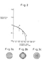
- According to studies and measurements made by the inventor, using an Interfaco interference microscope under conditions to be explained later, however, the graded index optical transmission element fabricated according to the above-mentioned method provides a refractive index distribution curve "b" of Fig. 2. In the range of 0.5r₀ to 0.75r₀ of radial distances from the center (i.e., in the range of c to d in the figure, with e being an outermost part), the curve b is relatively close to the ideal curve expressed by the equation (1). At the outer and inner sides of the above range, however, the refractive index distribution is greatly deviated from the ideal curve.
- When a grid pattern is observed through these optical transmission elements, if the optical transmission element has a refractive index pattern which almost correctly follows the quadratic curve defined by the equation (1), the article will provide a normal grid image as shown in Fig. 3(a). If, however, the refractive index distribution of the optical transmission element deviates from the ideal refractive index distribution, as indicated by (b) of Fig. 2, the element will provide a distorted grid image as shown in Figs. 3(b) and 3(c), since the element cannot transmit a incorrect image. In this case, a modulation transfer factor (MTF) indicating the resolution of the element is also very low, i.e., less than 30% which is not acceptable for use as an optical transmission element of a facsimile.
- Accordingly, the conventional graded-index optical transmission element with the refractive index distribution as shown by (b) of Fig. 2 must be cut or eluted by a solvent process to remove a portion outer than the position (d) of Fig. 2, thereby providing the optical transmission element with an optical path having a relatively ideal refractive index distribution. It is, however, difficult to provide an optical transmission element with a high resolution, and thus the productivity thereof is very low, and it is very difficult to constantly produce elements having a uniform quality.
- An object of the invention is to provide a method of manufacturing a plastic graded-index optical transmission element which can be applied to a facsimile and an image sensor employing a monochromatic light source and has a high resolution and a less chromatic aberration.
- The invention provides a method of manufacturing a plastic graded-index optical transmission element having a circular cross section of a radius r₀, the plastic graded-index optical transmission element formed having a refractive index distribution which substantially approximates a refractive index distribution curve defined by the following equation (1), at least in a limited range extending from the center axis toward the peripheral face of the optical transmission element:

- n₀ is the refractive index at the centre axis of the optical transmission element;
- n(r) is the refractive index at a position of a radius r away from the centre axis of the optical transmission element;
- g is the refractive index distribution constant (mm⁻¹) of the optical transmission element; and
- r is the distance (mm) from the centre axis toward the periphery of the optical transmission element wherein,
-
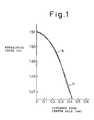
- Fig. 1 shows a refractive index distribution curve of an example of a graded-index type optical transmission element of the invention;
- Fig. 2 shows a refractive index distribution curve of a plastic graded-index optical transmission element formed according to a prior art method;
- Fig. 3 is a view of examples of grid images obtained by these optical transmission elements;
- Fig. 4 is a schematic view of an apparatus for measuring the resolution of an optical transmission element;
- Fig. 5 is a graph of the light quantity levels of a grid image measured with a CCD sensor;
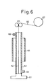
- Fig. 6 is a schematic view of an apparatus preferably used for forming the plastic graded-index optical transmission element of the invention; and
- Fig. 7 is a schematic view of a lens property measuring apparatus.
- As indicated by (b) of Fig. 1, the refractive index distribution curve of the optical transmission element manufactured according to the invention must substantially approximate the ideal refractive index distribution curve ((a) of Fig. 1) expressed with the equation (1), at least in the range of 0.25r₀ to 0.70r₀ , preferably 0.20r₀ to 0.75r₀, from the center axis of the element. The plastic graded-index optical transmission element manufactured according to the invention involving the above-mentioned range which agrees with the ideal refractive index distribution defined by the equation (1) provides a nearly correct image of a grid observed with the optical transmission element, even if the refractive index distribution of the optical transmission element relatively deviates from the refractive index distribution curve defined by the equation (1) in the region ranging from the center axis to 0.25r₀ or in the region outside 0.70r₀.
- The plastic graded-index optical transmission element manufactured according to the invention must have a value n₀ of 1.4 ≦ n₀ ≦ 1.6. If the value exceeds 1.6, the optical transmission plastic element is difficult to produce, and if the value n₀ is smaller than 1.4, the difference of refractive indexes at the center axis and at the periphery of the element cannot be enlarged, to thus realize an optical transmission element having an excellent resolution and image transmitting characteristics.
- A value g is defined by the following equation (3):

- When the plastic graded-index optical transmission element manufactured according to the invention is used for a facsimile, etc., a plurality of such elements instead of a single element thereof are usually arranged in a single row or a plurality of rows in a zigzag manner, to form an array of the optical transmission elements in which images provided by the elements partly overlap each other to form an image. The visibility of the overlapped images depends on the degree of overlapping, which is influenced by the diameter of each optical transmission element. To obtain a clear image, the radius r₀ of the optical transmission element must be in the range of 0.4 to 0.6 mm. If the element is thinner than this, the element may have an insufficient brightness and be difficult to produce with a uniform refractive index distribution. If the element is thicker than the above range, the images provided by the array of the optical transmission elements may unevenly overlap each other, and thus will not transmit clear images. By setting the MTF of the array over 40%, the array can transmit clearer and brighter images.
- The MTF which indicates resolution of the plastic graded-index optical transmission element of the invention can be determined as follows. Namely, as shown in Fig. 4, a
light source 42, afilter 43, adiffusion plate 44, agrid 45, and anarray 47 composed of a plurality of plastic graded-indexoptical transmission elements 41 form a resolution measuring apparatus. A grid image having a spatial frequency of 4 (line-pairs/mm) is passed through theoptical transmission elements 41 to form an image on aCCD line sensor 46. The formed grid image is read, and the maximum value (imax) and the minimum value (imin) of light quantities of the image are measured as shown in Fig. 5. According to the measured imax and imin , the MTF is calculated according to the imax and imin with the following equation (2):
grid 45 of Fig. 4. - The MTF of the plastic graded-index optical transmission element of the invention must be not less than 55%. If the MTF is smaller than 55%, the optical transmission element provides a low resolution and cannot form a clear image when applied to a copying machine such as a facsimile.
- The plastic graded-index optical transmission element of the invention may be fabricated in the following manner:
- N (N ≧ 3) uncured liquid substances each having a viscosity of between 10³ and 10⁸ poises in an uncured state and refractive indexes n of n₁ > n₂ > n₃ ... nN in a cured state are prepared, and these uncured liquid substances are concentrically laminated, one upon the other, in such a way that the refractive indexes are successively reduced from the center toward the periphery of the laminated substances, thereby forming an uncured strand fiber. The substances of the strand fiber are then mutually diffused between adjacent layers to provide a continuous refractive index distribution between the layers, during which or thereafter the uncured strand fiber is cured.
- If a difference of n₁ - nN between the central and outermost layers of the distributed refractive index type optical transmission article is enlarged with N being 2, it will be difficult to approximate the refractive index distribution of the element to the curve defined by the equation (1), in the range of 0.25r₀ to 0.75r₀ from the center of the element, and the optical transmission element manufactured according to the invention will hardly be obtained. Accordingly, N must be 3 or greater than 3, preferably 3 to 7, and more preferably 3 to 5.
- When carrying out the invention, each of the uncured liquid substances must have a viscosity between 10³ and 10⁸ poises and be curable. If the viscosity is smaller than 10³ poises, the strand will be easily broken and hardly form a strand-like shape. If the viscosity is greater than 10⁸ poises, the substance will have a poor processability which will lead to a deterioration of the concentricity or forming of irregular diameters.
- The liquid substances to be employed when carrying out the invention may be radical polymerizable vinyl monomers, or compositions comprising the monomers and polymers that are soluble with the monomers.
- The radical polymerizable vinyl monomers to be used are, for example, methyl methacrylate (n = 1.49), styrene (n = 1.59), chlorostyrene (n = 1.61), vinyl acetate (n = 1.47), fluorized alkyl(meta)acrylate (n = 1.37 to 1.44) such as 2,2,3,3-tetrafluoropropyl(meta)acrylate, 2,2,3,3,4,4,5,5-octafluoropropyl(meta)acrylate, 2,2,3,4,4,4-hexafluoropropyl(meta)acrylate, and 2,2,2-trifluoroethyl(meta)acrylate, and (meta)acrylates having a refractive index between 1.43 and 1.62 such as ethyl(meta)acrylate, phenyl(meta)acrylate, benzyl(meta)acrylate, hydroxylalkyl(meta)acrylate, alkyleneglycoldi(meta)acrylate, trimethylolpropane-di or -tri(meta)acrylate, pentaerythritol-di, -tri, or -tetra(meta)acrylate, diglycerintetra(meta)acrylate, dipentaerythritolhexa(meta)acrylate, as well as diethyleneglycolbisallyl-carbonate, fluorized alkyleneglycolpoly(meta)acrylate, etc. In order to adjust the viscosities of these uncured liquid substances and make the distribution of the refractive indexes of an obtained strand fiber from the center toward the outside of the strand fiber, the uncured liquid substances are preferably composed of vinyl-based monomers and soluble polymers. The polymers to be used must have a good compatibility with polymers produced from the radical polymerizable vinyl monomers. The polymers are, for example, poly(methyl methacrylate) (n = 1.49), poly(methylmethacrylate)-based copolymer (n = 1.47 to 1.50), poly-4-methylpenten-1 (n = 1.46), ethylene/vinyl acetate copolymer (n = 1.46 to 1.50), polycarbonate (n = 1.50 to 1.57), poly(vinylidene fluoride) (n = 1.42), vinylidene fluoride/tetrafluoroethylene copolymer (n = 1.42 to 1.46), vinylidene fluoride/tetrafluoroethylene/hexafluoropropene copolymer (n = 1.40 to 1.46), and poly(alkylfluoride) (meta) acrylate polymer.
- To adjust the viscosities, it is preferable to use polymers having an identical refractive index for respective layers, because an optical transmission plastic element having refractive indexes continuously distributed from the center toward the surface of the element can be formed. In particular, poly(methyl methacrylate) has an excellent transparency and a high refractive index, and therefore, is preferably used for producing the plastic graded-index optical transmission elements in accordance with the invention.
- To cure the strand fiber formed from the uncured substances, it is preferable to add a thermosetting catalyst and/or photocatalyst to the uncured substances. The fiber strand containing the thermosetting catalyst and/or photocatalyst is heated or irradiated with light, preferably ultraviolet light.
- The thermosetting catalyst may be a peroxide-based catalyst, and the photopolymerization catalyst may be benzophenone, benzoinalkylether, 4'-isopropyl-2-hydroxy-2-methyl-propiophenone, 1-hydroxycyclohexylphenylketone, benzylmethylketal, 2,2-diethoxyacetophenone, chlorothioxanthone, thioxanthone-based compounds, benzophenone-based compounds, 4-dimethylaminobenzoic ethyl, 4-dimethylaminobenzoic isoamyl, N-methyldiethanolamine, triethylamine, etc.
- The light source used for the photopolymerization may be a carbon arc lamp, a high-pressure mercury lamp, an ultra-high-pressure mercury lamp, a low-pressure mercury lamp, a chemical lamp, a xenon lamp, or a laser beam, etc., emitting light having a wavelength of 150 to 600 nm.
- To prepare the optical transmission element of the invention, a strand fiber forming apparatus shown in Fig. 6, for example, may be used. A concentric
composite nozzle 61 extrudes anuncured strand fiber 62, which is passed through amutual diffusion portion 63 for mutually diffusing monomers of respective layers of the strand fiber to impart a refractive index distribution, as well as through a curingportion 64 for curing the uncured substances. The strand fiber is then passed between pullingrollers 65, and wound, as a plastic graded-indexoptical transmission element 66, around a windingportion 67. To remove volatilizing substances released from thestrand fiber 62 from themutual diffusion portion 63 and from the curingportion 64, an inert gas such as nitrogen gas is introduced from an inertgas introducing port 68, and discharged from a dischargingport 69. - The invention will be explained in more detail with reference to Examples.
- The lens properties and refractive index distributions of the Examples were measured as follows:
- The lens properties were measured with an evaluation apparatus shown in Fig. 7.
- Each optical transmission element prepared according to the Examples was cut to a length of about one fourth (λ/4) of a period (λ) of a light beam. The period (λ) was determined from the wave form of a He-Ne laser beam passing through the element. The element was then polished with a polisher to make both end faces of the sample parallel to each other and orthogonal to a longitudinal axis, and thus a sample to be evaluated was obtained.
- As shown in Fig. 7, a sample table (76) was placed on an optical bench (71), and a sample (78) to be evaluated was placed on the sample table (76). A diaphragm (74) was adjusted so that light from a light source (72) passes through a condenser lens (73), the diaphragm (74), and a glass plate (75) and entirely irradiates an end face of the sample. Thereafter, the sample (78) and a Polaroid camera (77) were adjusted so that the light was focused on a film in the Polaroid (a trademark of the Polaroid company) camera. An image of a square grid was photographed, and the distortion of the grid was observed. The glass plate (75) was a chrome-plated photomasking glass, the chrome film on which was precisely processed to form a square grid pattern of 0.1 mm.
- An Interfaco interference microscope made by the Carl Zeiss company was used for this measurement.
- Poly(methyl methacrylate) ([η] = 0.56 measured in methylethylketone (MEK) at 25°C) of 46 weight portions, benzylmethacrylate of 44 parts by weight, methylmethacrylate of 10 parts by weight, 1-hydroxycyclohexylphenylketone of 0.2 part by weight, and hydroquinone of 0.1 part by weight were heated and mixed at 70°C to form an original liquid for forming a first layer (a central portion). Poly(methyl methacrylate) ([η] = 0.41 measured in MEK at 25°C) of 50 parts by weight, methylmethacrylate of 50 parts by weight, 1-hydroxycyclohexylphenylketone of 0.2 parts by weight, and hydroquinone of 0.1 part by weight were heated and mixed at 70°C to form an original liquid for forming a second layer. Poly(methyl methacrylate) ([η] = 0.34 measured in MEK at 25°C) of 45 parts by weight, 2,2,3,3,4,4,5,5-octafluoropentylmethacrylate of 35 parts by weight, methylmethacrylate of 20 parts by weight, 1-hydroxycyclohexylphenylketone of 0.2 part by weight, and hydroquinone of 0.1 part by weight were heated and mixed at 70°C to form an original liquid for forming a third layer (an outer layer portion). The forming apparatus of Fig. 6 was provided with a concentric three-layer composite spinning nozzle. With this apparatus, the three kinds of the original liquids were simultaneously extruded to form a concentric strand fiber in a manner that the refractive indexes of the uncured substances decreased from the center toward the periphery of the strand fiber. During this extrusion, the viscosity of the first layer components was 4.5 x 10⁴ poises, that of the second layer components was 2.0 x 10⁴ poises, and that of the third layer components was 2.2 x 10⁴ poises. The temperature of the composite spinning nozzle was 55°C.
- Thereafter, the strand fiber was passed through the mutual diffusion portion of 90 cm in length and the center of a light irradiating portion composed of 12 fluorescent lamps of 120 cm long and output 40 W each equidistantly arranged in a ring shape. At a speed of 50 cm/min, the optical transmission element of 0.50 mm in radius (r₀) was pulled by nip rollers. The ratio of discharged quantities of the first, second, and third layers was 1:1:1. The optical transmission element thus produced had distributed refractive indexes of 1.512 at a central portion (n₀) and 1.470 at a peripheral portion, and a refractive index distribution constant (g) of 0.52. As shown in Fig. 1, a refractive index distribution of the element substantially approximated the equation (1) in the range of 0.25r₀ to 0.75r₀ extending from the center toward the external face of the article.
- Both end faces of the optical transmission element were polished to a lens length of 7.2 mm for which an MTF was measured with the grid of 4 line-pairs/mm, and the MTF was 57% at a conjugate length of 15.4 mm. An obtained grid image was clear with minor distortion.
- A plurality of the optical transmission elements were employed to form an optical transmission element array having a lens length of 7.1 mm as indicated by the numeral 47 in Fig. 4, the MTF thereof was measured with a grid of 4 line-pairs/mm, and it was found that the MTF was 49% at a conjugate length of 15.4 mm. This optical transmission element array, an LED light source, and a light receiving CCD element were assembled into an image scanner, which produced a high resolution and was able to transmit clear images.
- The original liquid for the first layer of the Example 1 was used as an original liquid for forming a first layer. Poly(methyl methacrylate) ([η] = 0.40 measured in MEK at 25°C) of 50 parts by weight, methylmethacrylate of 20 parts by weight, benzylmethacrylate of 30 parts by weight, 1-hydroxycyclohexylphenylketone of 0.2 part by weight, and hydroquinone of 0.1 part by weight were heated and mixed at 65°C to form an original liquid for forming a second layer. The original liquid for the second layer of the Example 1 was used as an original liquid for forming a third layer. Poly(methyl methacrylate) ([η] = 0.40 measured in MEK at 25°C) of 50 parts by weight, methylmethacrylate of 30 parts by weight, 2,2,3,3-tetrafluoropropylmethacrylate of 20 parts by weight, 1-hydroxycyclohexylphenylketone of 0.2 parts by weight, and hydroquinone of 0.1 part by weight were heated and mixed at 65°C to form an original liquid for forming a fourth layer, and thereafter the four kinds of original liquids were simultaneously extruded from a concentric four-layer composite spinning nozzle to form a strand fiber in a manner similar to the Example 1. During this extrusion, the viscosity of the original liquid for the first layer was 4.5 x 10⁴ poises, that of the original liquid for the second layer was 4.0 x 10⁴ poises, that of the original liquid for the third layer was 2.0 x 10⁴ poises, and that of the original liquid for the fourth layer was 7.2 x 10⁴ poises. The temperature of the composite nozzle was 60°C.
- Thereafter, similar to the Example 1, the strand fiber was cured to form a plastic optical transmission element having a radius (r₀) of 0.48 mm. The ratio of discharged quantities of the first, second, third, and fourth layers was 2:1:1:1. The optical transmission element thus produced had distributed refractive indexes measured with the Interfaco interference microscope of 1.513 at a central portion (n₀) and 1.497 at a peripheral portion, and a refractive index distribution constant (g) of 0.53. The refractive index distribution of the element substantially approximated the equation (1), in the range of 0.2r₀ to 0.8r₀ extending from the center toward the external face of the element. The MTF measured with a grid of 4 line-pairs/mm, was 60% at a lens length of 7.1 mm and a conjugate length of 14.9 mm. A plurality of the optical transmission elements were employed to form an optical transmission element array in a manner similar to the Example 1. The MTF of the array was 53%. Similar to the image scanner of the Example 1, an image scanner employing this array achieved high resolution and could transmit clear images.
- The original liquid for forming the first layer of the Example 2 was used as an original liquid for forming a fourth layer. The original liquid for forming the third layer of the Example 1 was used as an original liquid for forming a fifth layer. The original liquids for the first to the fifth layers were simultaneously extruded from a concentric composite nozzle in a manner similar to the Example 1 into a strand fiber from which an optical transmission element of 0.48 mm in radius (r₀) was obtained in a manner similar to the Example 1.
- The ratio of discharged quantities of the first, second, third, fourth, and fifth layers was 3:1:1:1:2. The optical transmission element thus produced had distributed refractive indexes measured with the Interfaco interference microscope of 1.514 at a central portion (n₀) and 1.469 at a peripheral portion, and a refractive index distribution constant (g) of 0.57. The refractive index distribution of the element substantially approximated the equation (1) in the range of 0.15r₀ to 0.85r₀ extending from the center toward the external face of the element. The MTF of the element was 65% at a lens length of 8.0 mm and a conjugate length of 15.9 mm. The MTF of an array of the optical transmission elements similar to that of the Example 1 was 60% (measured with a grid of 4 line-pairs/mm). An image scanner employing this array produced a high resolution and was able to transmit clear images.
- A mixture of 2,2,3,3-tetrafluoropropylmethacrylate ([η] = 2.268 measured in MEK at 25°C) of 60 parts by weight, methacrylate of 40 parts by weight, 1-hydroxycyclohexylphenylketone of 0.1 part by weight, and hydroquinone of 0.1 part by weight was heated to 80°C, passed through a mixing portion, and extruded from a nozzle of 2.0 mm in diameter. During this extrusion, the mixed substances had a viscosity of 1 x 10⁴ poises. A strand fiber obtained by the extrusion was heated to 80°C, and passed, for 13 minutes, through a volatilizing portion, through which a nitrogen gas was flowing at 10 liters/min, thereby volatilizing a part of the methylmethacrylate from the surface of the strand fiber. Thereafter, the strand fiber was passed through the central part of six very-high pressure mercury lamps of 500 W each equidistantly disposed in a circular shape, and irradiated with light for about 0.5 minutes. The strand fiber was then taken up by nip rollers.
- The optical transmission element thus obtained had a radius (r₀) of 0.35 mm, distributed refractive indexes measured with the Interfaco interference microscope of 1.441 at a central portion (n₀) and 1.427 at a peripheral portion, and a refractive index distribution constant (g) of 0.48. The refractive index distribution of the element approximated the equation (1) in the range of 0.35r₀ to 0.5r₀ extending from the center toward the peripheral face of the element. The MTF of the element measured with a grid of 4 line-pairs/mm was 23% at a lens length of 8.0 mm and a conjugate length of 15.9 mm. obtained image of the grid had a large distortion.
- A plurality of the optical transmission elements were assembled into an optical transmission element array in a manner similar the Example 1. The MTF of the array measured with a grid of 4 line-pairs/mm was 13%. An image scanner employing this array achieved very poor resolution and was inappropriate for transmitting images.
- Poly(methyl methacrylate) ([η] = 0.45 measured in MEK at 25°C) of 50 parts by weight, methylmethacrylate of 40 parts by weight, phenylmethacrylate of 10 parts by weight, 1-hydroxycyclohexylphenylketone of 0.2 part by weight, and hydroquinone of 0.1 part by weight were heated and mixed at 60°C to prepare an original liquid for forming a first layer. Poly(methyl methacrylate) ([η] = 0.40 measured in MEK at 25°C) of 48 parts by weight, methylmethacrylate of 40 parts by weight, 2,2,3,3-tetrafluoropropylmethacrylate of 12 parts by weight, 1-hydroxycyclohexylphenylketone of 0.2 part by weight, and hydroquinone of 0.1 part by weight were heated and mixed at 60°C to prepare an original liquid for forming a second layer. Poly(methyl methacrylate) ([η] = 0.34 measured in MEK at 25°C) of 40 weight portions, 2,2,3,3,4,4,5,5-octafluoropentylmethacrylate of 40 parts by weight, methylmethacrylate of 20 parts by weight, 1-hydroxycyclohexylphenylketone of 0.2 part by weight, and hydroquinone of 0.1 part by weight were heated and mixed at 60°C to prepare an original liquid for forming a third layer. These original liquids were simultaneously extruded from a concentric composite nozzles. At this time, the viscosity of the first layer components was 5.0 x 10⁴ poises, that of the second layer components was 3.5 x 10⁴ poises, and that of the third layer components was 2.4 x 10⁴ poises. The temperature of the composite nozzle was 60°C.
- The ratio of discharged quantities of the first, second, and third layers was 2:1:1. Similar to the Example 1, the strand fiber thus prepared was diffused and cured into an optical transmission element of r₀ = 0.52. This optical transmission element had distributed refractive indexes measured with the Interfaco interference microscope of 1.495 at a central portion (n₀) and 1.461 at a peripheral portion, and a refractive index distribution constant (g) of 0.41 mm⁻¹. The refractive index distribution of the element substantially approximated the equation (1) in the range of 0.18r₀ to 0.75r₀ extending from the center toward the external face of the product. The MTF of the element was 60% at a lens length of 9.1 mm and a conjugate length of 19.8 mm. An optical transmission element array prepared in a manner similar to the Example 1 had an MTF of 56% (measured with the grid of 4 line-pairs/mm). This array was assembled into an image scanner, which achieved high resolution and could transmit clear images.
- The three kinds of the original liquids used in the Example 4 were employed at a ratio of discharged quantities of first, second, and third layers of 2.2:1:0.8 to form a strand fiber in a manner similar to the Example 4. The strand fiber was cured into an optical transmission element of 0.60 mm in radius (r₀). The optical transmission element had distributed refractive indexes measured with the Interfaco interference microscope of 1.494 at a central portion and 1.463 at a peripheral portion, and a refractive index distribution constant (g) of 0.34 mm⁻¹. The refractive index distribution of the element substantially approximated the equation (1), in the range of 0.19r₀ to 0.76r₀ extending from the center toward the external face of the article. The MTF of the element was 57% at a lens length of 11.3 mm and a conjugate length of 22.1 mm. The MTF of an optical transmission element array formed in a manner similar to the Example 1 was 50% (measured with a grid of 4 line-pairs/mm) at a lens length of 11.3 mm and a conjugate length of 22.1 mm. This array was assembled into an image scanner, which produced a high resolution and was able to transmit clear images.
- The three kinds of the original liquids prepared in the Example 4 were employed at a ratio of discharged quantities of first, second, and third layers of 4.0:1.0:3.0 to form a strand fiber in a manner similar to the Example 4. The strand fiber was cured into an optical transmission element of 0.50 mm in radius (r₀). The optical transmission element had distributed refractive indexes measured by the Interfaco interference microscope of 1.498 at a central portion and 1.459 at a peripheral portion, and a refractive index distribution constant (g) of 0.46 mm⁻¹. The refractive index distribution of the element substantially approximated the equation (1) in the range of 0.30r₀ to 0.65r₀ extending from the center toward the external face of the element. The MTF of the element was 35% at a lens length of 8.4 mm and a conjugate length of 16.0 mm. The MTF of an optical transmission element array formed in a manner similar to the Example 1 was 30% at a lens length of 8.4 mm and a conjugate length of 16.0 mm. This array was assembled into an image scanner, which produced a poor resolution, distorted images, and blurred edges.
- Compared with an optical transmission element of the prior art of the same kind, the plastic graded-index optical transmission element of the invention substantially approximates the ideal distribution curve of the equation (1), at least in the range of 0.25r₀ to 0.75r₀ from the center of the element, and therefore, without cutting of the peripheral portion thereof, the elements manufactured according to the invention provide excellent lens characteristics. The optical transmission elements manufactured according to the invention, therefore, may be effectively used for a facsimile and an image sensor which require a high resolution.
- The optical transmission element manufactured according to the invention can efficiently be manufactured by concentrically extruding at least three uncured substances into at least three laminated layers.
- A plurality of the optical transmission elements can be arranged in a single row or in a plurality of rows to form an optical transmission element array, which may effectively be used as an image transmitting member of a copying machine or of a facsimile. The optical transmission element array preferably has a lens length (Zn) between 5 and 15 mm, preferably between 6 and 12 mm, and an image forming length (Tc) between 10 and 40 mm, preferably between 13 and 25 mm. With these values, the optical transmission element array may have uniform characteristics, a uniform length, and such a high resolution as an MTF measured with a grid of 4 line-pairs/mm of more than 30%, preferably more than 40%.
-
- 41: optical transmission element
- 42: light source
- 43: filter
- 44: diffusion plate
- 45: grid
- 46: CCD line sensor
- 47: array
- 61: composite nozzle
- 62: uncured strand fiber
- 63: mutual diffusion portion
- 64: curing portion
- 65: take-up roller
- 66: optical transmission element
- 67: winding portion
- 71: optical bench
- 72: light source
- 73: condensing lens
- 74: diaphragm
- 75: glass plate
- 76: sample table
- 77: Polaroid camera
- 78: sample
Claims (4)
- A method of manufacturing a plastic graded-index optical transmission element having a circular cross section of radius r₀ wherein a value of r₀ is from 0.4 mm to 0.6 mm, and having a refractive index distribution which substantially approximates a refractive index distribution curve defined by the following equation (1) at least in a limited range extending from the center axis toward the peripheral face of the optical transmission element:
 n₀ is the refractive index at the centre axis of the optical transmission element;n(r) is the refractive index at a position of radius r away from the centre axis of the optical transmission element;g is the refractive index distribution constant (mm⁻¹) of the optical transmission element;r is the distance (mm) from the centre axis toward the peripheral face of the optical transmission element; and
characterized in that, 0.3 ≤ g (mm⁻¹) ≤ 0.7, in that said limited range approximating equation (1) extends from 0.25r₀ to 0.70r₀, and in that the method comprises the steps of preparing N (N ≥ 3) uncured liquid substances each having a viscosity between 10³ and 10⁸ poises and refractive indexes n of n₁ > n₂ > n₃ ..... nx when cured, concentrically laminating the substances in such a way that the refractive indexes are successively reduced from the centre toward the periphery of the laminated substances to form an uncured strand fibre, mutually diffusing the substances between adjacent layers in such a way that the refractive indexes are substantially continuously distributed between the layers, and at the same time or thereafter, curing the uncured strand fibre, and in that when a grid image of 4 line-pairs/mm is formed through the optical transmission element on a CCD line sensor and the maximum value imax and the minimum value imin of light quantities of the image are measured, the modulation transfer function (MTF) calculated according to the following equation (2) :
- A method of manufacturing a plastic graded-index optical transmission element according to claim 1, wherein the uncured liquid substances comprise a mixture of poly(methyl methacrylate) and radical polymerisable vinyl monomers.
- A method according to claim 1 or claim 2 in which the refractive index distribution of the optical transmission element formed substantially approximates the refractive index distribution curve defined by the equation (1) at least in the range of 0.20r₀ to 0.75r₀ extending from the center axis toward the peripheral face of the optical transmission element.
- A method of manufacturing an optical transmission element array comprising manufacturing of a plurality of plastic graded-index optical transmission elements manufactured according to the method of any of claims 1 to 3 and assembly of said elements in a single line or a plurality of lines.
Applications Claiming Priority (1)
| Application Number | Priority Date | Filing Date | Title |
|---|---|---|---|
| PCT/JP1989/000990 WO1991005274A1 (en) | 1989-09-29 | 1989-09-29 | Refractive index distribution type plastic optical transfer member and its production method |
Publications (3)
| Publication Number | Publication Date |
|---|---|
| EP0447548A1 EP0447548A1 (en) | 1991-09-25 |
| EP0447548A4 EP0447548A4 (en) | 1992-07-08 |
| EP0447548B1 true EP0447548B1 (en) | 1996-01-17 |
Family
ID=13958869
Family Applications (1)
| Application Number | Title | Priority Date | Filing Date |
|---|---|---|---|
| EP89910942A Expired - Lifetime EP0447548B1 (en) | 1989-09-29 | 1989-09-29 | Method of manufacturing a plastic graded-index optical transmission element |
Country Status (5)
| Country | Link |
|---|---|
| US (1) | US5175786A (en) |
| EP (1) | EP0447548B1 (en) |
| KR (1) | KR0154877B1 (en) |
| DE (1) | DE68925483T2 (en) |
| WO (1) | WO1991005274A1 (en) |
Families Citing this family (10)
| Publication number | Priority date | Publication date | Assignee | Title |
|---|---|---|---|---|
| US5390274A (en) * | 1989-09-29 | 1995-02-14 | Mitsubishi Rayon Company Ltd. | Distributed graded index type optical transmission plastic article and method of manufacturing same |
| US5235660A (en) * | 1992-07-10 | 1993-08-10 | Peachtree Fiberoptics, Inc. | Graded polymer optical fibers and process for the manufacture thereof |
| DE69331093T2 (en) * | 1992-08-17 | 2002-03-14 | Yasuhiro Koike | Process for the production of plastic light guides |
| US6106745A (en) * | 1995-11-30 | 2000-08-22 | Akzo Nobel Nv | Method of making graded index polymeric optical fibers |
| US6086999A (en) * | 1997-06-12 | 2000-07-11 | Boston Optical Fiber, Inc. | Method for producing a graded index plastic optical material |
| EP1059544B1 (en) * | 1998-02-24 | 2003-06-04 | Mitsubishi Rayon Co., Ltd. | Plastic optical fiber, optical fiber cable, optical fiber cable with plug, method for producing methyl methacrylate based polymer and method for producing plastic optical fiber |
| US6776932B1 (en) * | 1998-06-12 | 2004-08-17 | Getronics Wang Co. Llc | Polymeric optical articles |
| DE10214533B4 (en) * | 2002-04-02 | 2004-11-25 | Deutsche Telekom Ag | Method and device for producing an optical polymer fiber |
| JP2006053210A (en) * | 2004-08-10 | 2006-02-23 | Mitsubishi Rayon Co Ltd | Manufacturing method of distributed refraction index plastic rod lens |
| US11648723B2 (en) * | 2019-12-03 | 2023-05-16 | Racing Optics, Inc. | Method and apparatus for reducing non-normal incidence distortion in glazing films |
Citations (2)
| Publication number | Priority date | Publication date | Assignee | Title |
|---|---|---|---|---|
| US4568146A (en) * | 1982-10-21 | 1986-02-04 | Sumitomo Electric Industries, Ltd. | Plastic optical fiber and production thereof |
| EP0208159A2 (en) * | 1985-06-12 | 1987-01-14 | Mitsubishi Rayon Co., Ltd. | Process for Producing an optical Transmission Medium |
Family Cites Families (6)
| Publication number | Priority date | Publication date | Assignee | Title |
|---|---|---|---|---|
| US4331380A (en) * | 1980-05-21 | 1982-05-25 | Xerox Corporation | Gradient index lens array having reduction properties |
| US4435039A (en) * | 1981-11-02 | 1984-03-06 | Xerox Corporation | Method and apparatus for improving image quality of a reduction/enlargement gradient index lens array |
| US4589736A (en) * | 1984-11-23 | 1986-05-20 | Xerox Corporation | Two row reduction/enlargement gradient index lens array having square-ended fibers |
| JPS62215204A (en) * | 1986-03-17 | 1987-09-21 | Mitsubishi Rayon Co Ltd | Production of plastic optical transmission body |
| KR950003433B1 (en) * | 1986-03-27 | 1995-04-12 | 미쓰비시 레이욘 가부시끼가이샤 | Plastic optical transmission medium process for producing the same and array of lenses using the same |
| US4878234A (en) * | 1987-02-16 | 1989-10-31 | Siemens Aktiengesellschaft | Dental x-ray diagnostics installation for producing panorama slice exposures of the jaw of a patient |
-
1989
- 1989-09-29 KR KR1019910700534A patent/KR0154877B1/en not_active IP Right Cessation
- 1989-09-29 US US07/689,942 patent/US5175786A/en not_active Expired - Lifetime
- 1989-09-29 DE DE68925483T patent/DE68925483T2/en not_active Expired - Lifetime
- 1989-09-29 EP EP89910942A patent/EP0447548B1/en not_active Expired - Lifetime
- 1989-09-29 WO PCT/JP1989/000990 patent/WO1991005274A1/en active IP Right Grant
Patent Citations (2)
| Publication number | Priority date | Publication date | Assignee | Title |
|---|---|---|---|---|
| US4568146A (en) * | 1982-10-21 | 1986-02-04 | Sumitomo Electric Industries, Ltd. | Plastic optical fiber and production thereof |
| EP0208159A2 (en) * | 1985-06-12 | 1987-01-14 | Mitsubishi Rayon Co., Ltd. | Process for Producing an optical Transmission Medium |
Also Published As
| Publication number | Publication date |
|---|---|
| DE68925483T2 (en) | 1996-07-11 |
| DE68925483D1 (en) | 1996-02-29 |
| KR920702889A (en) | 1992-10-28 |
| KR0154877B1 (en) | 1998-12-15 |
| US5175786A (en) | 1992-12-29 |
| EP0447548A1 (en) | 1991-09-25 |
| WO1991005274A1 (en) | 1991-04-18 |
| EP0447548A4 (en) | 1992-07-08 |
Similar Documents
| Publication | Publication Date | Title |
|---|---|---|
| EP0451266B1 (en) | Method of manufacturing a plastic graded-index optical transmission element | |
| US4822122A (en) | Optical transmission medium and process for producing the same based on vinylidene flouride polymers and metharylate polymers | |
| EP0447548B1 (en) | Method of manufacturing a plastic graded-index optical transmission element | |
| US7777964B2 (en) | Plastic rod lens, rod lens array, rod lens plate, image sensor and printer | |
| US4799761A (en) | Plastic optical transmission medium, process for producing the same and array of lenses using the same | |
| EP0527239B1 (en) | Manufacturing method of a graded index type optical transmission element | |
| JP3291583B2 (en) | Indexable plastic optical transmitter, optical transmitter array, and image scanner | |
| JP3072116B2 (en) | Manufacturing method of graded index plastic optical transmitter | |
| JP3328615B2 (en) | Graded-index plastic optical transmitter | |
| JP2893046B2 (en) | Method of manufacturing refractive index distribution type plastic optical transmission body | |
| JP3370658B2 (en) | Graded-index plastic optical transmitter | |
| JPH063533A (en) | Production of distributed refractive index type plastic light transmission body | |
| JPH11352307A (en) | Method for using light transmission body or light transmission body array, and color image sensor | |
| JP3008361B2 (en) | Manufacturing method of graded index plastic optical transmitter | |
| JP3850941B2 (en) | Optical transmitter array | |
| JP3945849B2 (en) | OPTICAL TRANSMITTER, OPTICAL TRANSMITTER ARRAY, USE THEREOF, AND COLOR IMAGE SENSOR | |
| JPH07146416A (en) | Refraction factor distribution type light transmission body, and manufacture thereof | |
| JP2009192629A (en) | Plastic rod lens, rod lens array, rod lens plate, image sensor and printer | |
| JP2010139959A (en) | Plastic rod lens, method of manufacturing the same, and plastic rod lens array | |
| JP2000035518A (en) | Light transmission body, light transmission body array, image sensor, lens plate and image forming device | |
| JPH08211242A (en) | Optical transmission body and its production and optical transmission body array | |
| JPH04251805A (en) | Refractive index distribution type plastic optical transmission body | |
| JP2006154856A (en) | Method for manufacturing optical transmission member | |
| JPH0553017A (en) | Linear light emitting body |
Legal Events
| Date | Code | Title | Description |
|---|---|---|---|
| PUAI | Public reference made under article 153(3) epc to a published international application that has entered the european phase |
Free format text: ORIGINAL CODE: 0009012 |
|
| 17P | Request for examination filed |
Effective date: 19910528 |
|
| AK | Designated contracting states |
Kind code of ref document: A1 Designated state(s): CH DE FR GB LI NL |
|
| A4 | Supplementary search report drawn up and despatched |
Effective date: 19920515 |
|
| AK | Designated contracting states |
Kind code of ref document: A4 Designated state(s): CH DE FR GB LI NL |
|
| 17Q | First examination report despatched |
Effective date: 19940613 |
|
| GRAA | (expected) grant |
Free format text: ORIGINAL CODE: 0009210 |
|
| AK | Designated contracting states |
Kind code of ref document: B1 Designated state(s): CH DE FR GB LI NL |
|
| REF | Corresponds to: |
Ref document number: 68925483 Country of ref document: DE Date of ref document: 19960229 |
|
| REG | Reference to a national code |
Ref country code: CH Ref legal event code: NV Representative=s name: BUGNION S.A. |
|
| ET | Fr: translation filed | ||
| PLBE | No opposition filed within time limit |
Free format text: ORIGINAL CODE: 0009261 |
|
| STAA | Information on the status of an ep patent application or granted ep patent |
Free format text: STATUS: NO OPPOSITION FILED WITHIN TIME LIMIT |
|
| 26N | No opposition filed | ||
| REG | Reference to a national code |
Ref country code: GB Ref legal event code: IF02 |
|
| PGFP | Annual fee paid to national office [announced via postgrant information from national office to epo] |
Ref country code: CH Payment date: 20050928 Year of fee payment: 17 |
|
| PG25 | Lapsed in a contracting state [announced via postgrant information from national office to epo] |
Ref country code: CH Free format text: LAPSE BECAUSE OF NON-PAYMENT OF DUE FEES Effective date: 20060930 Ref country code: LI Free format text: LAPSE BECAUSE OF NON-PAYMENT OF DUE FEES Effective date: 20060930 |
|
| REG | Reference to a national code |
Ref country code: CH Ref legal event code: PL |
|
| PGFP | Annual fee paid to national office [announced via postgrant information from national office to epo] |
Ref country code: FR Payment date: 20080915 Year of fee payment: 20 Ref country code: NL Payment date: 20080915 Year of fee payment: 20 |
|
| PGFP | Annual fee paid to national office [announced via postgrant information from national office to epo] |
Ref country code: DE Payment date: 20081002 Year of fee payment: 20 |
|
| PGFP | Annual fee paid to national office [announced via postgrant information from national office to epo] |
Ref country code: GB Payment date: 20081001 Year of fee payment: 20 |
|
| REG | Reference to a national code |
Ref country code: GB Ref legal event code: PE20 Expiry date: 20090928 |
|
| PG25 | Lapsed in a contracting state [announced via postgrant information from national office to epo] |
Ref country code: GB Free format text: LAPSE BECAUSE OF EXPIRATION OF PROTECTION Effective date: 20090928 Ref country code: NL Free format text: LAPSE BECAUSE OF EXPIRATION OF PROTECTION Effective date: 20090929 |
|
| NLV7 | Nl: ceased due to reaching the maximum lifetime of a patent |