EP0447136B1 - A method for automatic switching and control of lighting - Google Patents
A method for automatic switching and control of lighting Download PDFInfo
- Publication number
- EP0447136B1 EP0447136B1 EP91301957A EP91301957A EP0447136B1 EP 0447136 B1 EP0447136 B1 EP 0447136B1 EP 91301957 A EP91301957 A EP 91301957A EP 91301957 A EP91301957 A EP 91301957A EP 0447136 B1 EP0447136 B1 EP 0447136B1
- Authority
- EP
- European Patent Office
- Prior art keywords
- light source
- light
- light intensity
- sensed
- reference level
- Prior art date
- Legal status (The legal status is an assumption and is not a legal conclusion. Google has not performed a legal analysis and makes no representation as to the accuracy of the status listed.)
- Revoked
Links
- 238000000034 method Methods 0.000 title claims abstract description 11
- 238000001514 detection method Methods 0.000 claims description 14
- 238000005286 illumination Methods 0.000 claims description 3
- 230000001419 dependent effect Effects 0.000 abstract description 6
- 239000003990 capacitor Substances 0.000 description 10
- 230000001276 controlling effect Effects 0.000 description 7
- 230000001105 regulatory effect Effects 0.000 description 6
- 238000010586 diagram Methods 0.000 description 3
- 230000000694 effects Effects 0.000 description 2
- 238000009434 installation Methods 0.000 description 2
- 230000035945 sensitivity Effects 0.000 description 2
- 102100023882 Endoribonuclease ZC3H12A Human genes 0.000 description 1
- 101710112715 Endoribonuclease ZC3H12A Proteins 0.000 description 1
- 101001044053 Mus musculus Lithostathine-1 Proteins 0.000 description 1
- XAGFODPZIPBFFR-UHFFFAOYSA-N aluminium Chemical compound [Al] XAGFODPZIPBFFR-UHFFFAOYSA-N 0.000 description 1
- 229910052782 aluminium Inorganic materials 0.000 description 1
- 239000004411 aluminium Substances 0.000 description 1
- 239000000919 ceramic Substances 0.000 description 1
- 238000006243 chemical reaction Methods 0.000 description 1
- 230000009977 dual effect Effects 0.000 description 1
- 238000010438 heat treatment Methods 0.000 description 1
- 229910052754 neon Inorganic materials 0.000 description 1
- GKAOGPIIYCISHV-UHFFFAOYSA-N neon atom Chemical compound [Ne] GKAOGPIIYCISHV-UHFFFAOYSA-N 0.000 description 1
- QGVYYLZOAMMKAH-UHFFFAOYSA-N pegnivacogin Chemical compound COCCOC(=O)NCCCCC(NC(=O)OCCOC)C(=O)NCCCCCCOP(=O)(O)O QGVYYLZOAMMKAH-UHFFFAOYSA-N 0.000 description 1
- 230000002265 prevention Effects 0.000 description 1
- 230000005855 radiation Effects 0.000 description 1
- 238000005476 soldering Methods 0.000 description 1
- 238000010998 test method Methods 0.000 description 1
- 230000001052 transient effect Effects 0.000 description 1
Images




Classifications
-
- H—ELECTRICITY
- H05—ELECTRIC TECHNIQUES NOT OTHERWISE PROVIDED FOR
- H05B—ELECTRIC HEATING; ELECTRIC LIGHT SOURCES NOT OTHERWISE PROVIDED FOR; CIRCUIT ARRANGEMENTS FOR ELECTRIC LIGHT SOURCES, IN GENERAL
- H05B41/00—Circuit arrangements or apparatus for igniting or operating discharge lamps
- H05B41/14—Circuit arrangements
- H05B41/36—Controlling
- H05B41/38—Controlling the intensity of light
- H05B41/39—Controlling the intensity of light continuously
- H05B41/392—Controlling the intensity of light continuously using semiconductor devices, e.g. thyristor
- H05B41/3921—Controlling the intensity of light continuously using semiconductor devices, e.g. thyristor with possibility of light intensity variations
- H05B41/3922—Controlling the intensity of light continuously using semiconductor devices, e.g. thyristor with possibility of light intensity variations and measurement of the incident light
-
- H—ELECTRICITY
- H05—ELECTRIC TECHNIQUES NOT OTHERWISE PROVIDED FOR
- H05B—ELECTRIC HEATING; ELECTRIC LIGHT SOURCES NOT OTHERWISE PROVIDED FOR; CIRCUIT ARRANGEMENTS FOR ELECTRIC LIGHT SOURCES, IN GENERAL
- H05B41/00—Circuit arrangements or apparatus for igniting or operating discharge lamps
- H05B41/14—Circuit arrangements
- H05B41/36—Controlling
-
- H—ELECTRICITY
- H05—ELECTRIC TECHNIQUES NOT OTHERWISE PROVIDED FOR
- H05B—ELECTRIC HEATING; ELECTRIC LIGHT SOURCES NOT OTHERWISE PROVIDED FOR; CIRCUIT ARRANGEMENTS FOR ELECTRIC LIGHT SOURCES, IN GENERAL
- H05B47/00—Circuit arrangements for operating light sources in general, i.e. where the type of light source is not relevant
- H05B47/10—Controlling the light source
- H05B47/105—Controlling the light source in response to determined parameters
- H05B47/11—Controlling the light source in response to determined parameters by determining the brightness or colour temperature of ambient light
-
- H—ELECTRICITY
- H05—ELECTRIC TECHNIQUES NOT OTHERWISE PROVIDED FOR
- H05B—ELECTRIC HEATING; ELECTRIC LIGHT SOURCES NOT OTHERWISE PROVIDED FOR; CIRCUIT ARRANGEMENTS FOR ELECTRIC LIGHT SOURCES, IN GENERAL
- H05B47/00—Circuit arrangements for operating light sources in general, i.e. where the type of light source is not relevant
- H05B47/10—Controlling the light source
- H05B47/105—Controlling the light source in response to determined parameters
- H05B47/115—Controlling the light source in response to determined parameters by determining the presence or movement of objects or living beings
-
- H—ELECTRICITY
- H05—ELECTRIC TECHNIQUES NOT OTHERWISE PROVIDED FOR
- H05B—ELECTRIC HEATING; ELECTRIC LIGHT SOURCES NOT OTHERWISE PROVIDED FOR; CIRCUIT ARRANGEMENTS FOR ELECTRIC LIGHT SOURCES, IN GENERAL
- H05B47/00—Circuit arrangements for operating light sources in general, i.e. where the type of light source is not relevant
- H05B47/10—Controlling the light source
- H05B47/105—Controlling the light source in response to determined parameters
- H05B47/115—Controlling the light source in response to determined parameters by determining the presence or movement of objects or living beings
- H05B47/13—Controlling the light source in response to determined parameters by determining the presence or movement of objects or living beings by using passive infrared detectors
-
- Y—GENERAL TAGGING OF NEW TECHNOLOGICAL DEVELOPMENTS; GENERAL TAGGING OF CROSS-SECTIONAL TECHNOLOGIES SPANNING OVER SEVERAL SECTIONS OF THE IPC; TECHNICAL SUBJECTS COVERED BY FORMER USPC CROSS-REFERENCE ART COLLECTIONS [XRACs] AND DIGESTS
- Y02—TECHNOLOGIES OR APPLICATIONS FOR MITIGATION OR ADAPTATION AGAINST CLIMATE CHANGE
- Y02B—CLIMATE CHANGE MITIGATION TECHNOLOGIES RELATED TO BUILDINGS, e.g. HOUSING, HOUSE APPLIANCES OR RELATED END-USER APPLICATIONS
- Y02B20/00—Energy efficient lighting technologies, e.g. halogen lamps or gas discharge lamps
- Y02B20/40—Control techniques providing energy savings, e.g. smart controller or presence detection
Definitions
- the present invention relates to a method for automatic switching and control of lighting to a localised area, the switching of the lighting being dependent on the presence or absence of a person in that localised area and the control of the lighting intensity being dependent on the sensed background level of lighting in that localised area. More particularly, but not exclusively, the invention relates to a lamp fitting and to an automatic control device for controlling the light output of a light source in a "self managed" and "self contained” energy saving luminaire.
- control devices for controlling the lighting conditions in a room as a function of the intensity of the daylight entering that room.
- Such devices operate with a controllable current supply to all the lights in a room, the current supply being varied in dependence on the sensed intensity of the daylight.
- the actual energy saved is limited by the centralised control of the lights many of which may be illuminating a localised area without anyone being present in that area.
- British Patent specification A-2 187 902 and United States Specification A-4 701 669 both disclose lighting control systems which are directed to controlling the light intensity at workstations, the former being also arranged to vary the lighting to correct for the relative level with the brightness of a VDU.
- both are complex hard wired installations with special controllers and both only consider the position on the assumption that a person is present.
- United States Specification No A-4 461 977 which document forms the base for the preamble of claims 1 and 3, discloses a lighting controller which is controlled by ambient light conditions and the presence of a person. It is a dedicated zone lighting controller for wiring into a complete system and simply ensures that the lights do not come on if a person is not present or if the ambient light level is sufficiently high.
- One object of the present invention is to provide a method for automatic control of lighting to a localised area which strives to provide an optimised energy saving by ensuring that the correct amount of lighting is provided to that area for specific requirements.
- the present invention provides a method of controlling the illumination of a localised area using a light source associated with the localised area, the method including: sensing for the presence of a person in the localised area; further sensing the light intensity in the localised area; establishing a reference level for sensed light intensity; controlling the light source by a) maintaining the light source in a dark luminous condition when no presence is sensed in the localised area; b) maintaining the light source in a dark luminous condition when a presence is sensed and the sensed light intensity is of at least said reference level and c) switching the light source to a high luminous condition which gives increased lighting in the localised area and maintaining the high luminous condition when a presence is sensed and the sensed light intensity is less than the reference level, characterised in that: the light source is in a self contained fitting, that the presence and light intensity are sensed from the fitting; and that the method further includes: establishing minimum and maximum output levels within the high luminous condition for the light source; adjusting the light source during the presence of the person
- the present invention also provides an automatic control device for controlling the light output from a light source, including: a lamp fitting incorporating a light source for illuminating a localised area; a presence detector for detecting the presence of a person in the localised area; a light detector for providing a signal related to the light intensity in the localised area; and control means connected to the presence detector, the light detector and the light source for controlling the light source, the control means being arranged to a) maintain the light source in a dark luminous condition when a presence is detected and the light intensity in the localised area is of at least a reference level; b) switch the light source to a high luminous condition which gives increased lighting in the localised area and maintain the light source in the high luminous condition when a presence is detected and the light intensity is less than the reference level; c) switch the light source to a dark luminous condition when detection of a presence ceases and d) switch the light source to a dark luminous condition when the light intensity exceeds the reference level characterised in that the fitting is
- the light source is connected to a dimmable electronic ballast, the ballast providing the power to drive the presence detector and the light detector.
- the presence detector is a passive infra-red detection device and the light detector is a photoresponsive device.
- each of the lamp fittings 1 is designed, in accordance with an embodiment of the invention, as an intelligent luminaire by which is meant that it incorporates a lighting control system that automatically adjusts its output to maintain a constant illumination onto a desk only when an occupant is within its operation range.
- Each luminaire consists of a self-contained 600 by 600mm recessed unit with a 16 cell low brightness aluminium reflector optic 2 suitable for VDU screen usage.
- the luminaire is fitted with energy efficient twin 40W 2L fluorescent lamps 3,4 the output of which is reflected by the reflector optic 2 to desired areas 7, only one of which is shown in Figure 1.
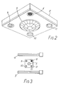
- a central control plate 8 In the centre of the reflector optic 2 is mounted a central control plate 8, see Figures 2 and 3, in which is mounted a passive infra-red presence detector 5 that brightens up the luminaire when a person is in the response area.
- the control plate 8 is also provided with a photocell 6 for detecting the light level in the operation range, a rotary switch 9 for adjusting the maximum output of the the lamps 3,4 and two further locations 10,11 which can be used for mounting additional sensors ,indicators or emergency lighting.
- the luminaire is connected to a lighting ring power supply and requires no other control or switching elements.
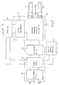
- FIG. 4 shows in block diagram form the overall luminaire control circuit which is split into two distinct parts, namely a Ballast housing 12 and a Sensor housing 14.
- the Sensor housing 14 contains a control pcb incorporating passive infra-red (PIR) and photocell detection circuits, while the Ballast housing 12 contains a 40W 2L Type C Electronic Mains Ballast (EMB) as well as a low voltage power supply (LVPS).
- PIR passive infra-red
- EMB 40W 2L Type C Electronic Mains Ballast
- LVPS low voltage power supply
- the Sensor unit can both 'dim' and turn 'on' and 'off' the ballast in accordance with a given stimulus such as ambient conditions and/or personnel detection.
- the luminaire control circuit is designed to be connected to the mains supply (220V/240V ac rms) at all times and is not subject to switch drops.
- the circuit is double protected via an external three Amp fuse in the mains plug and socket, as well as a 2. 7 Amp internal fuse in the ballast housing 12.
- the circuit will light the lamps L1,L2 only if a person is detected by the PIR as being within viewing range and if the light received back at the photocell detector is below a set regulating level.
- the light level will be adjusted automatically to hold the working illuminance at a constant level irrespective of ambient contribution from windows etc. If ambient light conditions become very high the EMB is capable of dimming down the lamp power.
- the circuit will switch off after a predetermined period, for example fifteen minutes, after its last detection.
- a threshold value for example twice the set regulating level
- the circuit will switch off after a predetermined period, for example fifteen minutes, after its last detection.
- the light level of the photocell detector must fall back to the regulating level or below. Should the person leave the detection area at any time the circuit will automatically turn off after a set period, for example fifteen minutes, after its last detection.
- the dimming function is achieved by varying a port on a Custom Control I.C. between three and five volts (five volts full power) using a grey sensor control lead.
- the on/off functionality is achieved by switching the low voltage supply to the control circuits of the EMB via an inhibit signal to a regulator using a green sensor lead.
- FIG 5 also shows in block form an overall luminaire control circuit with particular reference to the embodiment of Figures 1 to 3.
- the two 40W 2L lamps 3,4 are shown connected to a variable frequency electronic ballast 15.
- the ballast 15 has a dc level part into which the output of the photocell 6 is fed via suitable control electronics 17.
- the incoming mains is connected via an electronic filter 19 to a power supply unit 21 including a six part relay which is in turn connected to the infra-red detector 5.
- the output of the IR detector controls the ballast circuit 15 via an electronic switch 23.
- the output of the lamps 3,4 is also controlled by the radial distribution reflector optic 2.
- the two detectors 5,6 are set in the trim of the reflector optic 2 or into a channel within the optic 2 separating the two lamps 3,4.
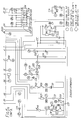
- FIG. 6a illustrates the basic circuitry for the Electronic Mains Ballast(EMB) and Low Voltage Power supply(LVPS). The layout shown is with relation to a hybrid layout where the control circuitry is held on a single ceramic hybrid. Much of the detail of the operation of the ballast is well known in the art and thus only a brief description of its major components is set out below.
- An input RFI filter circuit is provided which in Figure 6a comprises a set of capacitors C1,C2,C3,and C4 together with chokes L1,L2, and the output from the filter circuit is coupled to a bridge rectifier comprising diodes D1-D4 to provide a.c. to d.c. conversion.
- a preregulator is incorporated to produce a sinusoidal input current to the required harmonic limits while at the same time producing unity power factor and a constant 375 V d.c. supply on a reservoir capacitor C6, irrespective of the load (100% to 25% lamp power).
- a high frequency inverter stage is coupled to the preregulator and includes drive circuitry for a pair of bridge transistors TR4 and TR5.
- Conventional lamp ballasting and cathode heating circuitry is provided designed to produce the correct preheat and prestrike characteric as well as running conditions for the lamps in conjunction with the ballast control circuits.
- control circuitry and logic is provided to control starting and running of the lamps as well as assessing fault conditions such as lamps missing or deactivated, low reservoir capacitor voltages or a low control supply voltage. The last of these conditions is important in the operation of the lamp fitting in the embodiment in that if the 10V d.c. supply to the control circuits drops below 8.5V d.c. the ballast automatically stops the inverter, turning the lamps off. This is similar to the manner in which the lamp fitting turns its lamps on and off by switching the low voltage supply between 10V d.c. and 1.2 V d.c.
- the circuit embodiment of Figure 6a includes further features to those normally found in a conventional ballast.
- a neon indicator N1 to identify to service engineers and electricians that mains supply is still connected to the fitting even though the lamps may be out.
- a switch SW100 is provided which limits the maximum voltage that can be applied to the dim port between 4V d.c. and 5V d.c. In this way one can limit the maximum lamp power from between 75% and 100%.Thus one can simulate the use of 36w 2L lamps instead of 40w 2L lamps for installations where ceiling spacing of fittings is small and high maximum illuminances are measured.
- a surge arrestor SA100 is used to avoid mains borne transients from causing an over voltage on C6, the main reservoir capacitor. This is an important feature since the lamp fitting will remain connected to the mains even in an unloaded state. This arrestor also aids to the circuit passing the mains transient test procedures to acquire VDE approvals.
- a major feature which distinguishes the circuitry of Figure 6a over conventional ballast circuitry is the use made of a low voltage supply generated via a transformer T101,diodes D101-D104 and a capacitor C100.
- This low voltage supply is both used to generate 10 d.c. supply via regulator REG1 as well as to generate a d.c. supply of between 14V and 31V, dependent on mains level, for the sensor module.
- the ballast housing has three main leads with associated plug and socket, eight lamp leads with 2L lamp holders and four signal leads for connection to the sensor module, two for the d.c. power supply discussed above and two for dimming and turning the ballast 'on' and 'off'.
- Figure 6b illustrates the circuitry used to control the ballast described above with the terminals A,B,C,D connected to the corresponding lettered terminals of Figure 6a.
- the circuitry of Figure 6b may be considered in three distinct parts namely the power supply,the PIR detector circuit and the photocell and light level latches.
- the power supply is provided from the raw supply from the ballast circuit(14-31 V d.c.) which is double regulated via a chip regulator circuit(8V d.c.) and a resistor/zener regulator (6.2 V d.c.). This prevents any drop in load or noise from affecting the rails in the sensor and in particular the high gain amplifier which could result in retrigger. The most likely cause of such a load drop is when the ballast turns off.
- the PIR detector circuit forms the top part of the circuit of Figure 6b and is itself subdivided into four distinct parts,these are:-
- a transistor TR1 and a switch SW1 together with their associated resistors form a switchable constant current generator, switch SW1 is factory preset to position 4 where the circuit will attempt to achieve a regulating light level of some 120 LUX.
- the current is applied to a light dependent resistor (LDR1) which yields a voltage related to light level on the device.
- LDR1 light dependent resistor
- This voltage is input to an error amplifier/integrator formed by lC2:B the output of which controls TR2 producing a voltage on the dim wire D (grey lead) of between 3V and 5V (5V full power).
- the resistors R27 on the sensor and R24 on the ballast(figure 6a) set the minimum level at 3V while R102 on the ballast limits the maximum dc voltage to 4V instead of 5V which reduces maximum lamp power with the use of switch SW100.
- the ballast is only capable of dimming to 25% lamp power beyond which no further compensation as described above can take place.
- the LDR voltage will fall until it is below the reference at the node between R22 and R23.
- lC3:A clamps the output of the threshold detectors low, resulting in no further personnel detection.
- the circuit will clamp the shutdown S/D output low, switching the lamps off.
- the switchable constant current source is required to allow for different room reflectance conditions. If the room is primarily lightly coloured more light can be received back at the LDR causing dimming even though one may be requiring the ballast to run at full power (eg. in night time conditions). Thus by switching to a high current from the source one increases the LDR voltage allowing lamp power to increase.
- the luminaire described above will only come on when there is a human being within its effective area and will top up the task illuminance automatically as daylight fades.
- This self managed luminaire requires no switch drops and is suitable for small private or large open area lighting. It provides very high energy savings (60-80%), tremendous flexibility for space planning as no control wires are needed and no additional signals are required to activate the luminaire.
Landscapes
- Circuit Arrangement For Electric Light Sources In General (AREA)
- Circuit Arrangements For Discharge Lamps (AREA)
- Lasers (AREA)
- Fastening Of Light Sources Or Lamp Holders (AREA)
- Non-Portable Lighting Devices Or Systems Thereof (AREA)
- Discharge-Lamp Control Circuits And Pulse- Feed Circuits (AREA)
Applications Claiming Priority (2)
| Application Number | Priority Date | Filing Date | Title |
|---|---|---|---|
| GB9005454 | 1990-03-10 | ||
| GB909005454A GB9005454D0 (en) | 1990-03-10 | 1990-03-10 | Lamp fitting |
Publications (3)
| Publication Number | Publication Date |
|---|---|
| EP0447136A2 EP0447136A2 (en) | 1991-09-18 |
| EP0447136A3 EP0447136A3 (en) | 1992-04-29 |
| EP0447136B1 true EP0447136B1 (en) | 1995-06-28 |
Family
ID=10672425
Family Applications (1)
| Application Number | Title | Priority Date | Filing Date |
|---|---|---|---|
| EP91301957A Revoked EP0447136B1 (en) | 1990-03-10 | 1991-03-08 | A method for automatic switching and control of lighting |
Country Status (11)
| Country | Link |
|---|---|
| EP (1) | EP0447136B1 (da) |
| JP (1) | JPH04220998A (da) |
| AT (1) | ATE124598T1 (da) |
| AU (1) | AU629738B2 (da) |
| DE (1) | DE69110712T2 (da) |
| DK (1) | DK0447136T3 (da) |
| ES (1) | ES2073673T3 (da) |
| GB (1) | GB9005454D0 (da) |
| IE (1) | IE61415B1 (da) |
| NZ (1) | NZ237369A (da) |
| PT (1) | PT96981B (da) |
Cited By (1)
| Publication number | Priority date | Publication date | Assignee | Title |
|---|---|---|---|---|
| WO2019075515A1 (en) * | 2017-10-16 | 2019-04-25 | Lux Smart Pty Ltd | CONTROL SYSTEM FOR A LIGHT SOURCE |
Families Citing this family (34)
| Publication number | Priority date | Publication date | Assignee | Title |
|---|---|---|---|---|
| US5220250A (en) * | 1989-12-11 | 1993-06-15 | North American Philips Corp. | Fluorescent lamp lighting arrangement for "smart" buildings |
| WO1992020959A1 (de) * | 1991-05-22 | 1992-11-26 | Walter Baenziger | Verfahren zum betätigen einer raumbeleuchtung und vorrichtung zur durchführung des verfahrens |
| CH683383A5 (de) * | 1992-03-31 | 1994-02-28 | Knobel Lichttech | Verfahren und Schaltanordnung zum Ein- und Ausschalten künstlicher Lichtquellen in einem Raum in Abhängigkeit des in dem Raum herrschenden Beleuchtungsniveaus. |
| ES2050605B1 (es) * | 1992-07-16 | 1997-10-16 | Aplicaciones Electronicas Ind | Punto de luz inteligente. |
| US5327048A (en) * | 1993-02-26 | 1994-07-05 | North American Philips Corporation | Bi-level lighting control system for hid lamps |
| FI94204C (fi) * | 1993-10-28 | 1995-07-25 | Helvar Oy | Sähkötehoa kuluttavan laitteen ohjauslaite |
| DE4440048A1 (de) * | 1994-11-09 | 1996-05-15 | Wila Leuchten Gmbh | Lichtquellenregelungsvorrichtung |
| WO1996022668A1 (en) * | 1995-01-16 | 1996-07-25 | Negawatt Technologies Inc. | Energy management control system |
| US5668446A (en) * | 1995-01-17 | 1997-09-16 | Negawatt Technologies Inc. | Energy management control system for fluorescent lighting |
| US5662411A (en) * | 1995-03-20 | 1997-09-02 | Regent Lighting Corporation | Motion activated light fixture with fixed sensor |
| DE19514972A1 (de) * | 1995-04-24 | 1996-10-31 | Steinel Gmbh & Co Kg | Dämmerungsschalter |
| DE19521934A1 (de) * | 1995-06-07 | 1996-02-08 | Wilhelm Wirtz | Gerät zur regelbaren tageslichtabhängigen Lichtsteuerung, geeignet für den Einbau in Leuchten mit dimmbaren elektronischen Vorschaltgeräten |
| US5812422A (en) * | 1995-09-07 | 1998-09-22 | Philips Electronics North America Corporation | Computer software for optimizing energy efficiency of a lighting system for a target energy consumption level |
| FR2740591B1 (fr) * | 1995-10-27 | 1998-03-27 | Guermonprez Marc | Systeme lumineux de signalisation automatique d'emplacement libre |
| DE19608224A1 (de) * | 1996-03-04 | 1997-09-11 | Waldmann Gmbh & Co Herbert | Beleuchtungsanordnung mit von einem Lichtsensor gesteuerten Lichtquellen |
| DE29706523U1 (de) * | 1997-04-11 | 1998-08-13 | Leax Ltd., London | Beleuchtungs-Steuereinrichtung |
| EP0871350A3 (de) * | 1997-04-11 | 2000-09-20 | Steinel GmbH & Co. KG | Beleuchtungsvorrichtung |
| DE29706609U1 (de) * | 1997-04-12 | 1998-08-06 | Leax Ltd., London | Beleuchtungssystem |
| IT1293696B1 (it) * | 1997-04-29 | 1999-03-10 | L & S Srl | Componente integrato per la gestione di impianti di illuminazione ad esempio per mobili attrezzati |
| DE29811633U1 (de) * | 1998-06-30 | 1998-09-10 | Leax Ltd., London | Steuereinrichtung für Beleuchtungssystem |
| US6724159B2 (en) | 2001-12-27 | 2004-04-20 | Koninklijke Philips Electronics N.V. | Method and apparatus for controlling lighting based on user behavior |
| DE20300022U1 (de) | 2003-01-03 | 2003-04-17 | RIDI-Leuchten GmbH, 72417 Jungingen | Leuchte |
| KR200334515Y1 (ko) * | 2003-08-18 | 2003-11-28 | 황윤규 | 복합 센서가 일체로 구비된 절전형 자동 점멸 램프 |
| EP1899695B8 (en) | 2005-06-30 | 2012-06-27 | LED Roadway Lighting Ltd. | Method and system for luminance characterization |
| CA2656177C (en) | 2005-06-30 | 2015-04-21 | Streetlight Intelligence, Inc. | Adaptive energy performance monitoring and control system |
| DE102007048341A1 (de) * | 2007-08-08 | 2009-02-12 | Tridonicatco Gmbh & Co. Kg | Dimmen von Leuchtmittelbetriebsgeräten auf vorab definierte Pegel |
| US8570190B2 (en) | 2007-09-07 | 2013-10-29 | Led Roadway Lighting Ltd. | Centralized route calculation for a multi-hop streetlight network |
| US8290710B2 (en) | 2007-09-07 | 2012-10-16 | Led Roadway Lighting Ltd. | Streetlight monitoring and control |
| GB0807197D0 (en) * | 2008-04-19 | 2008-05-28 | Rylatt Paul | Illumination adjustment device |
| WO2010048652A2 (de) * | 2008-10-31 | 2010-05-06 | Tridonicatco Gmbh & Co Kg | Verfahren zur ansteuerung von leuchtmittelbetriebsgeräten |
| EP2842394B1 (en) | 2012-04-27 | 2020-01-08 | Schreder | Luminaire controllers |
| EP2670221A1 (en) * | 2012-06-01 | 2013-12-04 | Helvar Oy Ab | An apparatus, a method, an arrangement and a computer program for controlling operation of a light source |
| CN107872915B (zh) * | 2017-10-24 | 2020-08-14 | 上海西艾爱电子有限公司 | 一种电子式光控器 |
| CN109036962B (zh) * | 2018-10-08 | 2024-02-09 | 上海西艾爱电子有限公司 | 一种继电器线圈节能的驱动电路 |
Family Cites Families (6)
| Publication number | Priority date | Publication date | Assignee | Title |
|---|---|---|---|---|
| US4461977A (en) * | 1982-12-01 | 1984-07-24 | The United States Of America As Represented By The Secretary Of The Navy | Single zone lighting controller |
| CA1253198A (en) * | 1984-05-14 | 1989-04-25 | W. John Head | Compensated light sensor system |
| US4663521A (en) * | 1985-02-15 | 1987-05-05 | Rca Corporation | Infrared radiation controlled switch with a visible light detector |
| GB2187902A (en) * | 1986-03-13 | 1987-09-16 | Lutron Electronics Co | Lighting control system |
| US4843283A (en) * | 1987-08-24 | 1989-06-27 | Chen Jack Y C | Infrared ray detector control illumination system |
| GB2218506B (en) * | 1988-05-11 | 1993-01-13 | Graham Wild | Automatic lighting system |
-
1990
- 1990-03-10 GB GB909005454A patent/GB9005454D0/en active Pending
-
1991
- 1991-03-04 IE IE71891A patent/IE61415B1/en not_active IP Right Cessation
- 1991-03-08 PT PT96981A patent/PT96981B/pt active IP Right Grant
- 1991-03-08 AT AT91301957T patent/ATE124598T1/de not_active IP Right Cessation
- 1991-03-08 NZ NZ237369A patent/NZ237369A/xx unknown
- 1991-03-08 DE DE69110712T patent/DE69110712T2/de not_active Revoked
- 1991-03-08 EP EP91301957A patent/EP0447136B1/en not_active Revoked
- 1991-03-08 JP JP3043762A patent/JPH04220998A/ja active Pending
- 1991-03-08 ES ES91301957T patent/ES2073673T3/es not_active Expired - Lifetime
- 1991-03-08 DK DK91301957.6T patent/DK0447136T3/da active
- 1991-03-12 AU AU72831/91A patent/AU629738B2/en not_active Ceased
Cited By (1)
| Publication number | Priority date | Publication date | Assignee | Title |
|---|---|---|---|---|
| WO2019075515A1 (en) * | 2017-10-16 | 2019-04-25 | Lux Smart Pty Ltd | CONTROL SYSTEM FOR A LIGHT SOURCE |
Also Published As
| Publication number | Publication date |
|---|---|
| AU7283191A (en) | 1991-09-12 |
| DK0447136T3 (da) | 1995-09-25 |
| PT96981A (pt) | 1993-05-31 |
| PT96981B (pt) | 1998-10-30 |
| NZ237369A (en) | 1993-04-28 |
| GB9005454D0 (en) | 1990-05-09 |
| IE910718A1 (en) | 1991-09-11 |
| ES2073673T3 (es) | 1995-08-16 |
| IE61415B1 (en) | 1994-11-02 |
| JPH04220998A (ja) | 1992-08-11 |
| ATE124598T1 (de) | 1995-07-15 |
| DE69110712D1 (de) | 1995-08-03 |
| DE69110712T2 (de) | 1996-02-01 |
| EP0447136A2 (en) | 1991-09-18 |
| EP0447136A3 (en) | 1992-04-29 |
| AU629738B2 (en) | 1992-10-08 |
Similar Documents
| Publication | Publication Date | Title |
|---|---|---|
| EP0447136A2 (en) | A method for automatic switching and control of lighting | |
| US5498931A (en) | Method for automatic switching and control of lighting | |
| US7608807B2 (en) | Closed loop daylight harvesting light control system having auto-calibration | |
| EP0542425B1 (en) | Step-dimming magnetic regulator for discharge lamps | |
| CA2620541C (en) | Lighting load management system for lighting systems having multiple power circuits | |
| JP3531962B2 (ja) | 2レベル照明制御システム | |
| US4587459A (en) | Light-sensing, light fixture control system | |
| US5581158A (en) | Lamp brightness control circuit with ambient light compensation | |
| RU2249925C2 (ru) | Устройство управления освещением | |
| US4347461A (en) | Incident illumination responsive light control | |
| CA2053354A1 (en) | Circuit arrangement | |
| US7545101B2 (en) | Multi-zone closed loop daylight harvesting having at least one light sensor | |
| USRE32450E (en) | Light-sensing, light fixture control system | |
| CA2123226A1 (en) | Lamp brightness control circuit with ambient light compensation | |
| JP2011253716A (ja) | 照明制御装置及び画像処理装置 | |
| US8629620B2 (en) | Automatic lighting control device and system | |
| KR20220090722A (ko) | 지능형 조명등 제어 장치 및 방법 | |
| JPH05152077A (ja) | 自動調光システム | |
| JP2732782B2 (ja) | 自動調光照明装置 | |
| KR200414811Y1 (ko) | 장롱/드레스 룸의 조명 장치 | |
| KR900001692B1 (ko) | 형광등 자동 조광 장치 | |
| CA2140559A1 (en) | Energy management control system for fluorescent lighting | |
| JPH0266882A (ja) | 照明システム | |
| JPH01220396A (ja) | 適正照度制御システム | |
| JPH01253194A (ja) | 照明制御システム |
Legal Events
| Date | Code | Title | Description |
|---|---|---|---|
| PUAI | Public reference made under article 153(3) epc to a published international application that has entered the european phase |
Free format text: ORIGINAL CODE: 0009012 |
|
| AK | Designated contracting states |
Kind code of ref document: A2 Designated state(s): AT BE CH DE DK ES FR GB GR IT LI LU NL SE |
|
| PUAL | Search report despatched |
Free format text: ORIGINAL CODE: 0009013 |
|
| AK | Designated contracting states |
Kind code of ref document: A3 Designated state(s): AT BE CH DE DK ES FR GB GR IT LI LU NL SE |
|
| 17P | Request for examination filed |
Effective date: 19920603 |
|
| 17Q | First examination report despatched |
Effective date: 19931215 |
|
| RAP1 | Party data changed (applicant data changed or rights of an application transferred) |
Owner name: TLG PLC |
|
| GRAA | (expected) grant |
Free format text: ORIGINAL CODE: 0009210 |
|
| AK | Designated contracting states |
Kind code of ref document: B1 Designated state(s): AT BE CH DE DK ES FR GB GR IT LI LU NL SE |
|
| PG25 | Lapsed in a contracting state [announced via postgrant information from national office to epo] |
Ref country code: GR Free format text: LAPSE BECAUSE OF FAILURE TO SUBMIT A TRANSLATION OF THE DESCRIPTION OR TO PAY THE FEE WITHIN THE PRESCRIBED TIME-LIMIT Effective date: 19950628 |
|
| REF | Corresponds to: |
Ref document number: 124598 Country of ref document: AT Date of ref document: 19950715 Kind code of ref document: T |
|
| ITF | It: translation for a ep patent filed | ||
| REF | Corresponds to: |
Ref document number: 69110712 Country of ref document: DE Date of ref document: 19950803 |
|
| REG | Reference to a national code |
Ref country code: ES Ref legal event code: FG2A Ref document number: 2073673 Country of ref document: ES Kind code of ref document: T3 |
|
| ET | Fr: translation filed | ||
| REG | Reference to a national code |
Ref country code: DK Ref legal event code: T3 |
|
| PLBQ | Unpublished change to opponent data |
Free format text: ORIGINAL CODE: EPIDOS OPPO |
|
| PLBI | Opposition filed |
Free format text: ORIGINAL CODE: 0009260 |
|
| PLBQ | Unpublished change to opponent data |
Free format text: ORIGINAL CODE: EPIDOS OPPO |
|
| PG25 | Lapsed in a contracting state [announced via postgrant information from national office to epo] |
Ref country code: LU Free format text: LAPSE BECAUSE OF NON-PAYMENT OF DUE FEES Effective date: 19960331 |
|
| PLBI | Opposition filed |
Free format text: ORIGINAL CODE: 0009260 |
|
| PLBF | Reply of patent proprietor to notice(s) of opposition |
Free format text: ORIGINAL CODE: EPIDOS OBSO |
|
| 26 | Opposition filed |
Opponent name: WHITECROFT PLC. Effective date: 19960327 Opponent name: PHILIPS ELECTRONICS N.V. Effective date: 19960325 |
|
| 26 | Opposition filed |
Opponent name: SIEMENS AG Effective date: 19960327 Opponent name: WHITECROFT PLC. Effective date: 19960327 Opponent name: PHILIPS ELECTRONICS N.V. Effective date: 19960325 |
|
| NLR1 | Nl: opposition has been filed with the epo |
Opponent name: WHITECROFT PLC. Opponent name: PHILIPS ELECTRONICS N.V. |
|
| NLR1 | Nl: opposition has been filed with the epo |
Opponent name: SIEMENS AG Opponent name: WHITECROFT PLC. Opponent name: PHILIPS ELECTRONICS N.V. |
|
| PLBF | Reply of patent proprietor to notice(s) of opposition |
Free format text: ORIGINAL CODE: EPIDOS OBSO |
|
| PLBF | Reply of patent proprietor to notice(s) of opposition |
Free format text: ORIGINAL CODE: EPIDOS OBSO |
|
| RDAH | Patent revoked |
Free format text: ORIGINAL CODE: EPIDOS REVO |
|
| APAC | Appeal dossier modified |
Free format text: ORIGINAL CODE: EPIDOS NOAPO |
|
| APAE | Appeal reference modified |
Free format text: ORIGINAL CODE: EPIDOS REFNO |
|
| APAC | Appeal dossier modified |
Free format text: ORIGINAL CODE: EPIDOS NOAPO |
|
| PLBQ | Unpublished change to opponent data |
Free format text: ORIGINAL CODE: EPIDOS OPPO |
|
| PLAB | Opposition data, opponent's data or that of the opponent's representative modified |
Free format text: ORIGINAL CODE: 0009299OPPO |
|
| R26 | Opposition filed (corrected) |
Opponent name: KONINKLIJKE PHILIPS ELECTRONICS N.V. * 19960327 WH Effective date: 19960325 |
|
| NLR1 | Nl: opposition has been filed with the epo |
Opponent name: SIEMENS AG Opponent name: WHITECROFT PLC. Opponent name: KONINKLIJKE PHILIPS ELECTRONICS N.V. |
|
| APAE | Appeal reference modified |
Free format text: ORIGINAL CODE: EPIDOS REFNO |
|
| PLBQ | Unpublished change to opponent data |
Free format text: ORIGINAL CODE: EPIDOS OPPO |
|
| PLAB | Opposition data, opponent's data or that of the opponent's representative modified |
Free format text: ORIGINAL CODE: 0009299OPPO |
|
| PLBQ | Unpublished change to opponent data |
Free format text: ORIGINAL CODE: EPIDOS OPPO |
|
| PLAB | Opposition data, opponent's data or that of the opponent's representative modified |
Free format text: ORIGINAL CODE: 0009299OPPO |
|
| R26 | Opposition filed (corrected) |
Opponent name: KONINKLIJKE PHILIPS ELECTRONICS N.V. * 19960327 WH Effective date: 19960325 |
|
| APAC | Appeal dossier modified |
Free format text: ORIGINAL CODE: EPIDOS NOAPO |
|
| R26 | Opposition filed (corrected) |
Opponent name: KONINKLIJKE PHILIPS ELECTRONICS N.V. * 19960327 WH Effective date: 19960325 |
|
| NLR1 | Nl: opposition has been filed with the epo |
Opponent name: SIEMENS AG Opponent name: WHITECROFT PLC. Opponent name: KONINKLIJKE PHILIPS ELECTRONICS N.V. |
|
| NLR1 | Nl: opposition has been filed with the epo |
Opponent name: SIEMENS AG Opponent name: WHITECROFT PLC. Opponent name: KONINKLIJKE PHILIPS ELECTRONICS N.V. |
|
| REG | Reference to a national code |
Ref country code: GB Ref legal event code: IF02 |
|
| PGFP | Annual fee paid to national office [announced via postgrant information from national office to epo] |
Ref country code: GB Payment date: 20030204 Year of fee payment: 13 |
|
| PGFP | Annual fee paid to national office [announced via postgrant information from national office to epo] |
Ref country code: SE Payment date: 20030225 Year of fee payment: 13 |
|
| PGFP | Annual fee paid to national office [announced via postgrant information from national office to epo] |
Ref country code: ES Payment date: 20030305 Year of fee payment: 13 |
|
| PGFP | Annual fee paid to national office [announced via postgrant information from national office to epo] |
Ref country code: DK Payment date: 20030311 Year of fee payment: 13 |
|
| PGFP | Annual fee paid to national office [announced via postgrant information from national office to epo] |
Ref country code: FR Payment date: 20030319 Year of fee payment: 13 Ref country code: BE Payment date: 20030319 Year of fee payment: 13 |
|
| PGFP | Annual fee paid to national office [announced via postgrant information from national office to epo] |
Ref country code: CH Payment date: 20030320 Year of fee payment: 13 |
|
| PGFP | Annual fee paid to national office [announced via postgrant information from national office to epo] |
Ref country code: AT Payment date: 20030321 Year of fee payment: 13 |
|
| PGFP | Annual fee paid to national office [announced via postgrant information from national office to epo] |
Ref country code: NL Payment date: 20030331 Year of fee payment: 13 |
|
| PGFP | Annual fee paid to national office [announced via postgrant information from national office to epo] |
Ref country code: DE Payment date: 20030527 Year of fee payment: 13 |
|
| PLBP | Opposition withdrawn |
Free format text: ORIGINAL CODE: 0009264 |
|
| RDAF | Communication despatched that patent is revoked |
Free format text: ORIGINAL CODE: EPIDOSNREV1 |
|
| RDAG | Patent revoked |
Free format text: ORIGINAL CODE: 0009271 |
|
| STAA | Information on the status of an ep patent application or granted ep patent |
Free format text: STATUS: PATENT REVOKED |
|
| REG | Reference to a national code |
Ref country code: CH Ref legal event code: PL |
|
| 27W | Patent revoked |
Effective date: 20031103 |
|
| GBPR | Gb: patent revoked under art. 102 of the ep convention designating the uk as contracting state |
Free format text: 20031103 |
|
| REG | Reference to a national code |
Ref country code: SE Ref legal event code: ECNC |
|
| NLR2 | Nl: decision of opposition |
Effective date: 20031103 |
|
| APAH | Appeal reference modified |
Free format text: ORIGINAL CODE: EPIDOSCREFNO |
|
| PLAB | Opposition data, opponent's data or that of the opponent's representative modified |
Free format text: ORIGINAL CODE: 0009299OPPO |