EP0446959A2 - Method of manufacture of a substantially cylindrical shank with a centring arm transient in one piece into the shank - Google Patents
Method of manufacture of a substantially cylindrical shank with a centring arm transient in one piece into the shank Download PDFInfo
- Publication number
- EP0446959A2 EP0446959A2 EP91105233A EP91105233A EP0446959A2 EP 0446959 A2 EP0446959 A2 EP 0446959A2 EP 91105233 A EP91105233 A EP 91105233A EP 91105233 A EP91105233 A EP 91105233A EP 0446959 A2 EP0446959 A2 EP 0446959A2
- Authority
- EP
- European Patent Office
- Prior art keywords
- centering arm
- contact surfaces
- shaft
- area
- clamping device
- Prior art date
- Legal status (The legal status is an assumption and is not a legal conclusion. Google has not performed a legal analysis and makes no representation as to the accuracy of the status listed.)
- Withdrawn
Links
Images
Classifications
-
- B—PERFORMING OPERATIONS; TRANSPORTING
- B23—MACHINE TOOLS; METAL-WORKING NOT OTHERWISE PROVIDED FOR
- B23P—METAL-WORKING NOT OTHERWISE PROVIDED FOR; COMBINED OPERATIONS; UNIVERSAL MACHINE TOOLS
- B23P15/00—Making specific metal objects by operations not covered by a single other subclass or a group in this subclass
-
- B—PERFORMING OPERATIONS; TRANSPORTING
- B21—MECHANICAL METAL-WORKING WITHOUT ESSENTIALLY REMOVING MATERIAL; PUNCHING METAL
- B21K—MAKING FORGED OR PRESSED METAL PRODUCTS, e.g. HORSE-SHOES, RIVETS, BOLTS OR WHEELS
- B21K1/00—Making machine elements
- B21K1/76—Making machine elements elements not mentioned in one of the preceding groups
-
- B—PERFORMING OPERATIONS; TRANSPORTING
- B23—MACHINE TOOLS; METAL-WORKING NOT OTHERWISE PROVIDED FOR
- B23Q—DETAILS, COMPONENTS, OR ACCESSORIES FOR MACHINE TOOLS, e.g. ARRANGEMENTS FOR COPYING OR CONTROLLING; MACHINE TOOLS IN GENERAL CHARACTERISED BY THE CONSTRUCTION OF PARTICULAR DETAILS OR COMPONENTS; COMBINATIONS OR ASSOCIATIONS OF METAL-WORKING MACHINES, NOT DIRECTED TO A PARTICULAR RESULT
- B23Q1/00—Members which are comprised in the general build-up of a form of machine, particularly relatively large fixed members
- B23Q1/03—Stationary work or tool supports
-
- B—PERFORMING OPERATIONS; TRANSPORTING
- B23—MACHINE TOOLS; METAL-WORKING NOT OTHERWISE PROVIDED FOR
- B23Q—DETAILS, COMPONENTS, OR ACCESSORIES FOR MACHINE TOOLS, e.g. ARRANGEMENTS FOR COPYING OR CONTROLLING; MACHINE TOOLS IN GENERAL CHARACTERISED BY THE CONSTRUCTION OF PARTICULAR DETAILS OR COMPONENTS; COMBINATIONS OR ASSOCIATIONS OF METAL-WORKING MACHINES, NOT DIRECTED TO A PARTICULAR RESULT
- B23Q16/00—Equipment for precise positioning of tool or work into particular locations not otherwise provided for
- B23Q16/02—Indexing equipment
- B23Q16/08—Indexing equipment having means for clamping the relatively movable parts together in the indexed position
-
- Y—GENERAL TAGGING OF NEW TECHNOLOGICAL DEVELOPMENTS; GENERAL TAGGING OF CROSS-SECTIONAL TECHNOLOGIES SPANNING OVER SEVERAL SECTIONS OF THE IPC; TECHNICAL SUBJECTS COVERED BY FORMER USPC CROSS-REFERENCE ART COLLECTIONS [XRACs] AND DIGESTS
- Y10—TECHNICAL SUBJECTS COVERED BY FORMER USPC
- Y10T—TECHNICAL SUBJECTS COVERED BY FORMER US CLASSIFICATION
- Y10T29/00—Metal working
- Y10T29/49—Method of mechanical manufacture
- Y10T29/49636—Process for making bearing or component thereof
- Y10T29/49643—Rotary bearing
- Y10T29/49647—Plain bearing
- Y10T29/49648—Self-adjusting or self-aligning, including ball and socket type, bearing and component making
-
- Y—GENERAL TAGGING OF NEW TECHNOLOGICAL DEVELOPMENTS; GENERAL TAGGING OF CROSS-SECTIONAL TECHNOLOGIES SPANNING OVER SEVERAL SECTIONS OF THE IPC; TECHNICAL SUBJECTS COVERED BY FORMER USPC CROSS-REFERENCE ART COLLECTIONS [XRACs] AND DIGESTS
- Y10—TECHNICAL SUBJECTS COVERED BY FORMER USPC
- Y10T—TECHNICAL SUBJECTS COVERED BY FORMER US CLASSIFICATION
- Y10T29/00—Metal working
- Y10T29/49—Method of mechanical manufacture
- Y10T29/49636—Process for making bearing or component thereof
- Y10T29/49705—Coating or casting
-
- Y—GENERAL TAGGING OF NEW TECHNOLOGICAL DEVELOPMENTS; GENERAL TAGGING OF CROSS-SECTIONAL TECHNOLOGIES SPANNING OVER SEVERAL SECTIONS OF THE IPC; TECHNICAL SUBJECTS COVERED BY FORMER USPC CROSS-REFERENCE ART COLLECTIONS [XRACs] AND DIGESTS
- Y10—TECHNICAL SUBJECTS COVERED BY FORMER USPC
- Y10T—TECHNICAL SUBJECTS COVERED BY FORMER US CLASSIFICATION
- Y10T29/00—Metal working
- Y10T29/49—Method of mechanical manufacture
- Y10T29/49826—Assembling or joining
- Y10T29/4984—Retaining clearance for motion between assembled parts
-
- Y—GENERAL TAGGING OF NEW TECHNOLOGICAL DEVELOPMENTS; GENERAL TAGGING OF CROSS-SECTIONAL TECHNOLOGIES SPANNING OVER SEVERAL SECTIONS OF THE IPC; TECHNICAL SUBJECTS COVERED BY FORMER USPC CROSS-REFERENCE ART COLLECTIONS [XRACs] AND DIGESTS
- Y10—TECHNICAL SUBJECTS COVERED BY FORMER USPC
- Y10T—TECHNICAL SUBJECTS COVERED BY FORMER US CLASSIFICATION
- Y10T29/00—Metal working
- Y10T29/49—Method of mechanical manufacture
- Y10T29/49972—Method of mechanical manufacture with separating, localizing, or eliminating of as-cast defects from a metal casting [e.g., anti-pipe]
- Y10T29/49973—Compressing ingot while still partially molten
-
- Y—GENERAL TAGGING OF NEW TECHNOLOGICAL DEVELOPMENTS; GENERAL TAGGING OF CROSS-SECTIONAL TECHNOLOGIES SPANNING OVER SEVERAL SECTIONS OF THE IPC; TECHNICAL SUBJECTS COVERED BY FORMER USPC CROSS-REFERENCE ART COLLECTIONS [XRACs] AND DIGESTS
- Y10—TECHNICAL SUBJECTS COVERED BY FORMER USPC
- Y10T—TECHNICAL SUBJECTS COVERED BY FORMER US CLASSIFICATION
- Y10T29/00—Metal working
- Y10T29/49—Method of mechanical manufacture
- Y10T29/4998—Combined manufacture including applying or shaping of fluent material
- Y10T29/49982—Coating
- Y10T29/49984—Coating and casting
Definitions
- the present invention relates to a method for producing an essentially cylindrical shaft with a centering arm which integrally merges into the shaft and which can be fixed very precisely against a clamping device with a groove for receiving the centering arm, according to the preamble of patent claim 1.
- a shaft with a centering arm which integrally merges into the shaft is a common means for the highly precise positioning of any object, in particular a workpiece to be machined, in relation to a clamping device with a groove for receiving the centering arm.
- such a shaft is made from high-quality machine steel.
- the fine machining of the centering arm in the area of its contact surfaces with the groove of the clamping device is complex and therefore cost-intensive.
- the present invention has for its object to develop a method of the type mentioned in such a way that the shaft with its centering arm which integrally merges into the shaft is easier to manufacture, while still positioning the shaft with the centering arm with high precision the jig must be guaranteed.
- the shaft is first cast from a plastically deformable, relatively soft material, which can be done by metal die casting for the materials light metals and zinc alloy.
- the shaft can also be made of light metal, a zinc alloy or a sintered material. Even if high accuracies are observed, only a casting accuracy of the order of a few hundredths of a millimeter is achieved.
- the shaft, with its centering arm integrally passing into it is pressed into a calibration tool which plastically deforms the centering arm with the groove of the clamping device, at least in the area of the contact surfaces. With this plastic deformation, an accuracy of the contact surfaces in the micrometer range is achieved and furthermore a compression of the material in the region of the contact surfaces is achieved.
- the centering arm is preferably further solidified in the area of its contact surfaces by a surface treatment.
- the surface treatment can be the application of a metallic surface coating that is hard compared to the material of the centering arm or by anodizing events with little centering.
- the surface is preferably made of nickel.
- the shaft is placed in a container which contains a large number of small parts, which can be metal balls, for example, which each have the same or different diameters.
- the container is then moved for a certain period of time, so that the balls continuously hit the surface of the centering arm as a result of the movement. This results in a compression of the material on the surface of the centering arm and thus a solidification of the material.
- a certain surface structure is also obtained from a large number of small craters. This surface structure is very advantageous because the small craters can pick up smaller dirt particles without impairing the possible clamping accuracy.
- a method related to ball polishing is shot peening of the centering arm, whereby the surface experiences a smoothing of the grain boundaries and a strain hardening, especially when using an aluminum die casting.
- the type of treatment eliminates unwanted, flaky surface structures of an untreated die-cast aluminum.
- Another advantage of a non-nickel-plated die-cast aluminum surface in the area of the contact surface of the centering arm is that, when dirty, small particles that get between the centering arm and the clamping device are pressed into the aluminum material. Up to a certain degree of contamination, the positioning accuracy or repetition accuracy is not impaired.
- aluminum or an aluminum alloy is selected as the material for the shaft and the centering arm.
- Aluminum has proven to be particularly suitable for calibration or plastic deformation by being pressed into a calibration tool. Furthermore, when the shaft is manufactured with the centering arm made of aluminum, a desired reduction in weight is achieved compared to the weight that would have to be accepted when manufactured from a machine steel. If aluminum or an aluminum alloy is used, anodizing will also bring the desired surface hardness as a surface treatment.
- the preferred casting accuracy for the centering arm in the area of its contact surfaces is approximately 10 to 50 micrometers, preferably approximately 20 micrometers, the shape accuracy that can be achieved by the subsequent calibration, based on such casting accuracies, being in the range of 1 to 5 micrometers, usually approximately 3 micrometers.
- the specified casting accuracies can still be achieved with tolerable effort in the manufacture of the mold and the implementation of aluminum die casting or other casting.
- a particularly hard surface that is also manufacturing-technical easy to apply with die-cast aluminum, is achieved by nickel plating, anodizing or by mechanical surface treatment such as ball polishing or shot peening.
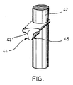
- the article produced by the process according to the invention and shown in perspective in the single figure comprises an essentially cylindrical shaft 42 with a centering arm 43 which extends integrally into the cylindrical shaft and extends at right angles to this centering arm 43 also with regard to its rotational position particularly precisely in relation to a known clamping device for such shanks with a groove for receiving the centering arm.
- the shaft 42 effects an axial alignment and the centering arm 43 performs a rotation angle alignment.
- the shaft 42 is cast together with the centering arm 43 in one piece in high-pressure aluminum casting.
- the shaft is then deep-drawn and the centering arm 43 is calibrated in the area of the desired contact surfaces 44, 45 by pressing it into a calibration tool (not shown), with a plastic deformation of the centering arm 43 in the area of the contact surfaces 44, 45 and surface compaction in this area.
- the shaft 42 is nickel-plated together with the centering arm 43 or with one other suitable, hard surface coating.
Abstract
Bei einem Verfahren zum Herstellen eines im wesentlichen zylindrischen Schaftes (66) mit einem einstückig in den Schaft (42) übergehenden Zentrierarm (43), der gegen eine Einspannvorrichtung mit einer Nut zum Aufnehmen des Zentrierarmes (43) hochgenau festlegbar ist, wird eine verbesserte Herstellbarkeit des Schaftes bei reduzierten Kosten durch folgende Herstellungsschritte erzielt: Metalldruckgießen, Sintern beziehungsweise Fließpressen des Schaftes (42) aus einem Leichtmetall, aus Messing, aus einer Zinklegierung oder aus einem Sintermaterial; und Kalibrieren des Zentrierarmes (43) zumindest im Bereich seiner Anlageflächen (44, 45) durch Eindrücken des Zentrierarmes in ein Kalibrierwerkzeug, das aus einem harten Material besteht, wobei der Zentierarm im Bereich der Anlageflächen eine plastische Materialverformung erfährt.In a method for producing an essentially cylindrical shaft (66) with a centering arm (43) which integrally merges into the shaft (42) and which can be fixed very precisely against a clamping device with a groove for receiving the centering arm (43), improved producibility becomes apparent of the shaft at reduced costs by the following manufacturing steps: metal die casting, sintering or extrusion of the shaft (42) from a light metal, from brass, from a zinc alloy or from a sintered material; and calibrating the centering arm (43) at least in the region of its contact surfaces (44, 45) by pressing the centering arm into a calibration tool which is made of a hard material, the centering arm being plastically deformed in the region of the contact surfaces.
Description
Die vorliegende Erfindung betrifft ein Verfahren zum Herstellen eines im wesentlichen zylindrischen Schaftes mit einem einstückig in den Schaft übergehenden Zentrierarm, der gegen eine Einspannvorrichtung mit einer Nut zur Aufnahme des Zentrierarmes hochgenau festlegbar ist, gemäß dem Oberbegriff des Patentanspruchs 1.The present invention relates to a method for producing an essentially cylindrical shaft with a centering arm which integrally merges into the shaft and which can be fixed very precisely against a clamping device with a groove for receiving the centering arm, according to the preamble of patent claim 1.
Ein Schaft mit einem einstückig in den Schaft übergehenden Zentrierarm ist ein gängiges Mittel zur hochgenauen Positionierung eines beliebigen Gegenstandes, insbesondere eines zu bearbeitenden Werkstückes, gegenüber einer Einspannvorrichtung mit einer Nut zur Aufnahme des Zentrierarmes.A shaft with a centering arm which integrally merges into the shaft is a common means for the highly precise positioning of any object, in particular a workpiece to be machined, in relation to a clamping device with a groove for receiving the centering arm.
Typischerweise wird ein derartiger Schaft aus einem hochwertigen Maschinenstahl gefertigt. Die Feinbearbeitung des Zentrierarmes im Bereich seiner Anlageflächen mit der Nut der Einspannvorrichtung ist aufwendig und damit kostenintensiv.Typically, such a shaft is made from high-quality machine steel. The fine machining of the centering arm in the area of its contact surfaces with the groove of the clamping device is complex and therefore cost-intensive.
Ausgehend von diesem Stand der Technik liegt der vorliegenden Erfindung die Aufgabe zugrunde, ein Verfahren der eingangs genannten Art so weiterzubilden, daß der Schaft mit seinem einstückig in den Schaft übergehenden Zentrierarm einfacher herstellbar ist, wobei dennoch eine hochgenaue Positionierung des Schaftes mit dem Zentrierarm gegenüber der Einspannvorrichtung gewährleistet sein muß.Based on this prior art, the present invention has for its object to develop a method of the type mentioned in such a way that the shaft with its centering arm which integrally merges into the shaft is easier to manufacture, while still positioning the shaft with the centering arm with high precision the jig must be guaranteed.
Diese Aufgabe wird durch ein Verfahren gemäß Patentanspruch 1 gelöst.This object is achieved by a method according to claim 1.
Bei dem Verfahren gemäß der vorliegenden Erfindung wird der Schaft zunächst aus einem plastisch verformbaren, relativ weichen Material gegossen, was durch Metalldruckguß für die Materialien Leichtmetalle und Zinklegierung erfolgen kann. Ebenfalls kann der Schaft aus Leichtmetall, einer Zinklegierung oder einem Sintermaterial gefertigt werden. Hierbei wird auch bei Einhaltung hoher Genauigkeiten lediglich eine Gußgenauigkeit in der Größenordnung von einigen Hundertstel Millimeter erreicht. Nachfolgend wird der Schaft mit seinem einstückig in ihn übergehenden Zentrierarm in ein Kalibrierwerkzeug gedrückt, das den Zentrierarm zumindest im Bereich der Anlageflächen mit der Nut der Einspannvorrichtung plastisch verformt. Bei dieser plastischen Verformung wird eine Genauigkeit der Anlageflächen im Mikrometerbereich erzielt und ferner eine Verdichtung des Materials im Bereich der Anlageflächen erreicht.In the method according to the present invention, the shaft is first cast from a plastically deformable, relatively soft material, which can be done by metal die casting for the materials light metals and zinc alloy. The shaft can also be made of light metal, a zinc alloy or a sintered material. Even if high accuracies are observed, only a casting accuracy of the order of a few hundredths of a millimeter is achieved. Subsequently, the shaft, with its centering arm integrally passing into it, is pressed into a calibration tool which plastically deforms the centering arm with the groove of the clamping device, at least in the area of the contact surfaces. With this plastic deformation, an accuracy of the contact surfaces in the micrometer range is achieved and furthermore a compression of the material in the region of the contact surfaces is achieved.
Vorzugsweise wird der Zentrierarm im Bereich seiner Anlageflächen durch eine Oberflächenbehandlung weiter verfestigt.The centering arm is preferably further solidified in the area of its contact surfaces by a surface treatment.
Die Oberflächenbehandlung kann das Aufbringen einer verglichen mit dem Material des Zentrierarmes harten metallischen Oberflächenbeschichtung oder durch eloxierendes zentrierarmes Geschehen.The surface treatment can be the application of a metallic surface coating that is hard compared to the material of the centering arm or by anodizing events with little centering.
Vorzugsweise besteht die Oberfläche aus Nickel.The surface is preferably made of nickel.
Es ist jedoch möglich, auch ohne eine derartige Oberflächenbehandlung auszukommen, da die Oberfläche des Zentrierarmes im Bereich der Anlageflächen durch den Herstellungsschritt des Kalibrierens mittels plastischer Materialverformung verfestigt ist.However, it is possible to do without such a surface treatment, since the surface of the centering arm is solidified in the area of the contact surfaces by the manufacturing step of calibration by means of plastic material deformation.
Die alleine auf diese Weise erzielte Oberflächenfestigkeit widerstand bei praktischen Versuchen 40.000 Wechsellasten, ohne daß eine für die Praxis bedeutungsvolle Abweichung in der Genauigkeit eingetreten wäre.The surface strength achieved in this way alone withstood practical tests 40,000 alternating loads, without a practical deviation in accuracy.
Für das erfindungsgemäße Verfahren ist es ohne Belang, ob der Herstellungsschritt des Vernickelns der Oberfläche vor oder nach dem Kalibrieren erfolgt. Erfolgt das Vernickeln nach dem Kalibrieren, so kann bei sehr hohen Genauigkeitsanforderungen noch ein weiteres Nachkalibrieren zweckmäßig sein.For the method according to the invention it is irrelevant whether the manufacturing step of nickel plating the surface takes place before or after the calibration. If the nickel plating takes place after the calibration, a further recalibration can be useful if the accuracy requirements are very high.
Ebenfalls ist es möglich, den Zentrierarm im Bereich seiner Anlageflächen durch Kugelpolieren weiterzubehandeln.It is also possible to further treat the centering arm in the area of its contact surfaces by ball polishing.
Beim Kugelpolieren wird der Schaft in einen Behälter gegeben, der eine Vielzahl kleiner Teile enthält, die beispielsweise Metallkugeln sein können, die jeweils gleiche oder auch unterschiedliche Durchmesser haben. Sodann wird der Behälter für eine gewisse Zeitdauer bewegt, so daß die Kügelchen durch die Bewegung laufend auf die Oberfläche des Zentrierarmes aufschlagen. Hierdurch erhält man eine Verdichtung des Materials an der Oberfläche des Zentrierarmes und damit eine Materialverfestigung. Auch erhält man eine gewisse Oberflächenstruktur durch eine Vielzahl von kleinen Kratern. Diese Oberflächenstruktur ist sehr vorteilhaft, da die kleinen Krater kleinere Schmutzpartikel aufnehmen können, ohne daß dadurch die mögliche Spanngenauigkeit beeinträchtigt wird.In the case of ball polishing, the shaft is placed in a container which contains a large number of small parts, which can be metal balls, for example, which each have the same or different diameters. The container is then moved for a certain period of time, so that the balls continuously hit the surface of the centering arm as a result of the movement. This results in a compression of the material on the surface of the centering arm and thus a solidification of the material. A certain surface structure is also obtained from a large number of small craters. This surface structure is very advantageous because the small craters can pick up smaller dirt particles without impairing the possible clamping accuracy.
Ein dem Kugelpolieren verwandtes Verfahren ist das Kugelstrahlen des Zentrierarmes, wodurch die Oberfläche insbesondere bei Verwenden eines Aluminiumdruckgusses eine Glättung der Korngrenzen und eine Kaltverfestigung erfährt. Die Art der Behandlung beseitigt unerwünschte, schuppenförmige Oberflächenstrukturen eines unbehandelten Aluminiumdruckgusses.A method related to ball polishing is shot peening of the centering arm, whereby the surface experiences a smoothing of the grain boundaries and a strain hardening, especially when using an aluminum die casting. The type of treatment eliminates unwanted, flaky surface structures of an untreated die-cast aluminum.
Ein weiterer Vorteil einer unvernickelten Aluminiumdruckgußoberfläche im Bereich der Anlagefläche des Zentrierarmes besteht darin, daß bei Verschmutzung kleine Partikel, die zwischen den Zentrierarm und die Einspannvorrichtung geraten, in das Aluminiummaterial eingedrückt werden. Bis zu einem gewissen Verschmutzungsgrad wird die Positioniergenauigkeit beziehungsweise Repetiergenauigkeit nicht beeinträchtigt.Another advantage of a non-nickel-plated die-cast aluminum surface in the area of the contact surface of the centering arm is that, when dirty, small particles that get between the centering arm and the clamping device are pressed into the aluminum material. Up to a certain degree of contamination, the positioning accuracy or repetition accuracy is not impaired.
Gemäß einer vorteilhaften Ausgestaltung wird als Material für den Schaft und den Zentrierarm Aluminium oder eine Aluminiumlegierung gewählt. Aluminium hat sich als besonders geeignet für die Kalibrierung oder plastische Verformung durch Einpressen in ein Kalibrierwerkzeug erwiesen. Ferner wird bei einer Herstellung des Schaftes mit dem Zentrierarm aus Aluminium eine erwünschte Reduzierung des Gewichtes gegenüber demjenigen Gewicht erzielt, das bei Herstellung aus einem Maschinenstahl hingenommen werden müßte. Verwendet man Aluminium oder eine Aluminiumlegierung, so wird als Oberflächenbehandlung auch ein Eloxieren die gewünschte Oberflächenhärte bringen.According to an advantageous embodiment, aluminum or an aluminum alloy is selected as the material for the shaft and the centering arm. Aluminum has proven to be particularly suitable for calibration or plastic deformation by being pressed into a calibration tool. Furthermore, when the shaft is manufactured with the centering arm made of aluminum, a desired reduction in weight is achieved compared to the weight that would have to be accepted when manufactured from a machine steel. If aluminum or an aluminum alloy is used, anodizing will also bring the desired surface hardness as a surface treatment.
Die bevorzugte Gußgenauigkeit für den Zentrierarm liegt im Bereich seiner Anlageflächen bei etwa 10 bis 50 Mikrometer, vorzugsweise etwa 20 Mikrometer, wobei die durch die anschließende Kalibrierung erzielbare Formgenauigkeit ausgehend von derartigen Gußgenauigkeiten im Bereich von 1 bis 5 Mikrometer, üblicherweise etwa 3 Mikrometer liegt.The preferred casting accuracy for the centering arm in the area of its contact surfaces is approximately 10 to 50 micrometers, preferably approximately 20 micrometers, the shape accuracy that can be achieved by the subsequent calibration, based on such casting accuracies, being in the range of 1 to 5 micrometers, usually approximately 3 micrometers.
Die angegebenen Gußgenauigkeiten lassen sich noch mit erträglichen Aufwand in der Herstellung der Gußform und der Durchführung des Aluminiumdruckgußes oder eines sonstigen Gußes erzielen.The specified casting accuracies can still be achieved with tolerable effort in the manufacture of the mold and the implementation of aluminum die casting or other casting.
Erstaunlicherweise wird trotz der relativ starken Abweichung der Gußform von der Sollform durch das Kalibrieren eine im Mikrometerbereich liegende Formtreue erzielt, wobei durch das Kalibrieren auch eine erste Verfestigung der Oberfläche auftritt. Eine besonders harte Oberfläche, die auch fertigungstechnisch bei Aluminiumdruckguß problemlos aufbringbar ist, wird durch Vernickeln, Eloxieren oder durch eine mechanische Oberflächenbehandlung wie Kugelpolieren oder Kugelstrahlen erzielt.Surprisingly, in spite of the relatively large deviation of the casting mold from the target shape, a dimensional accuracy in the micrometer range is achieved by the calibration, with the calibration also resulting in a first solidification of the surface. A particularly hard surface that is also manufacturing-technical easy to apply with die-cast aluminum, is achieved by nickel plating, anodizing or by mechanical surface treatment such as ball polishing or shot peening.
Nachfolgend wird unter Bezugnahme auf die beiliegende Zeichnung eine bevorzugte Ausführungsform eines nach dem erfindungsgemäßen Verfahren gefertigeten Schaftes mit einem einstückig in diesen übergehenden Zentrierarm näher erläutert.
Es zeigt:
- Die einzige Figur
- eine perspektivische Darstellung eines Schaftes mit einem einstückig in den Schaft übergehenden Zentrierarm.
It shows:
- The only figure
- a perspective view of a shaft with a centering arm integrally merging into the shaft.
Der nach dem erfindungsgemäßen Verfahren hergestellte und in der einzigen Figur perspektivisch dargestellte Gegenstand umfaßt einen im wesentlichen zylindrischen Schaft 42 mit einem einstückig in den zylindrischen Schaft übergehenden, rechtwinklig gegenüber diesem verlaufenden Zentrierarm 43. Ein solcher Schaft mit Zentrierarm läßt sich sowohl bezüglich seiner axialen Lage wie auch bezüglich seiner Drehlage besonders genau gegenüber einer an sich bekannten Einspannvorrichtung für derartige Schafte mit einer Nut zum Aufnehmen des Zentrierarmes festlegen. Innerhalb der Einspannvorrichtung bewirkt der Schaft 42 eine axiale Ausrichtung und der Zentrierarm 43 eine Drehwinkelausrichtung.The article produced by the process according to the invention and shown in perspective in the single figure comprises an essentially
Der Schaft 42 wird zusammen mit dem Zentrierarm 43 einstükkig im Aluminiumhochdruckguß gegossen. Anschließend wird der Schaft tiefgezogen und der Zentrierarm 43 im Bereich der gewünschten Anlageflächen 44, 45 durch Eindrücken in ein (nicht dargestelltes) Kalibrierwerkzeug kalibriert, wobei eine plastische Verformung des Zentrierarmes 43 im Bereich der Anlageflächen 44, 45 sowie eine Oberflächenverdichtung in diesem Bereich stattfindet. Anschließend wird der Schaft 42 zusammen mit dem Zentrierarm 43 vernickelt oder mit einer anderen geeigneten, harten Oberflächenbeschichtung versehen.The
Claims (8)
gekennzeichnet durch folgende Herstellungsschritte:
characterized by the following manufacturing steps:
daß vor oder nach dem Herstellungsschritt des Kalibrierens die Oberfläche des Zentrierarmes (43) zumindest im Bereich ihrer Anlageflächen (44, 45) mit der Nut der Einspannvorrichtung durch eine Oberflächenbehandlung weiter verfestigt wird.A method according to claim 1, characterized in
that before or after the manufacturing step of calibrating, the surface of the centering arm (43) is further solidified with the groove of the clamping device by a surface treatment, at least in the area of its contact surfaces (44, 45).
daß die Oberflächenbehandlung das Aufbringen einer verglichen mit dem Material des Zentrierarmes (43) harten metallischen Oberflächenbeschichtung beinhaltet.A method according to claim 2, characterized in
that the surface treatment includes the application of a hard metallic surface coating compared to the material of the centering arm (43).
daß die Oberflächenbehandlung das Eloxieren des Zentrierarmes (43) beinhaltet.A method according to claim 2, characterized in
that the surface treatment includes anodizing the centering arm (43).
daß die Oberflächenbehandlung ein Kugelpolieren oder Kugelstrahlen des Zentrierarmes (43) zumindest im Bereich seiner Anlageflächen (44, 45) mit der Einspannvorrichtung beinhaltet.A method according to claim 2, characterized in
that the surface treatment includes ball polishing or shot peening of the centering arm (43) at least in the area of its contact surfaces (44, 45) with the clamping device.
daß das Leichtmetall Aluminium oder eine Aluminiumlegierung ist.Method according to one of claims 1 to 5, characterized in that
that the light metal is aluminum or an aluminum alloy.
daß der Zentrierarm (43) beim Gießen im Bereich seiner Anlageflächen (44, 45) mit der Nut der Einspannvorrichtung mit einer Genauigkeit von etwa 10 bis 50 Mikrometer, üblicherweise etwa 20 Mikrometer, gegossen wird, und
daß die Formgenauigkeit der Anlageflächen (44, 45) nach deren plastischer Verformung durch das Kalibrieren in dem Bereich zwischen 1 und 5 Mikrometer, üblicherweise etwa 3 Mikrometer, liegt.Method according to one of claims 1 to 6, characterized in that
that the centering arm (43) is cast in the area of its contact surfaces (44, 45) with the groove of the clamping device with an accuracy of approximately 10 to 50 micrometers, usually approximately 20 micrometers, and
that the shape accuracy of the contact surfaces (44, 45) after their plastic deformation by calibration is in the range between 1 and 5 micrometers, usually about 3 micrometers.
daß die Oberflächenbeschichtung durch Vernickeln erzeugt wird.Method according to one of claims 1 to 3, characterized in that
that the surface coating is produced by nickel plating.
Applications Claiming Priority (4)
| Application Number | Priority Date | Filing Date | Title |
|---|---|---|---|
| DE3732206 | 1987-09-24 | ||
| DE19873732206 DE3732206A1 (en) | 1987-09-24 | 1987-09-24 | Method of producing a first article which can be secured with high precision relative to a second article |
| DE3814102 | 1988-04-26 | ||
| DE19883814102 DE3814102A1 (en) | 1988-04-26 | 1988-04-26 | Method for the production of a first object to be fixed with a high degree of precision relative to a second object |
Related Parent Applications (2)
| Application Number | Title | Priority Date | Filing Date |
|---|---|---|---|
| EP88115510A Division EP0308908B1 (en) | 1987-09-24 | 1988-09-21 | Method of making a second article, which is highly precise positionable to a first article |
| EP88115510.5 Division | 1988-09-21 |
Publications (2)
| Publication Number | Publication Date |
|---|---|
| EP0446959A2 true EP0446959A2 (en) | 1991-09-18 |
| EP0446959A3 EP0446959A3 (en) | 1991-09-25 |
Family
ID=25860108
Family Applications (3)
| Application Number | Title | Priority Date | Filing Date |
|---|---|---|---|
| EP19910105233 Withdrawn EP0446959A3 (en) | 1987-09-24 | 1988-09-21 | Method of manufacture of a substantially cylindrical shank with a centring arm transient in one piece into the shank |
| EP88115510A Expired - Lifetime EP0308908B1 (en) | 1987-09-24 | 1988-09-21 | Method of making a second article, which is highly precise positionable to a first article |
| EP91105234A Expired - Lifetime EP0446960B1 (en) | 1987-09-24 | 1988-09-21 | Method of manufacture of a pallet for receiving a workpiece |
Family Applications After (2)
| Application Number | Title | Priority Date | Filing Date |
|---|---|---|---|
| EP88115510A Expired - Lifetime EP0308908B1 (en) | 1987-09-24 | 1988-09-21 | Method of making a second article, which is highly precise positionable to a first article |
| EP91105234A Expired - Lifetime EP0446960B1 (en) | 1987-09-24 | 1988-09-21 | Method of manufacture of a pallet for receiving a workpiece |
Country Status (5)
| Country | Link |
|---|---|
| US (1) | US5036579A (en) |
| EP (3) | EP0446959A3 (en) |
| JP (1) | JPH069769B2 (en) |
| DE (1) | DE3884410D1 (en) |
| ES (2) | ES2044640T3 (en) |
Families Citing this family (17)
| Publication number | Priority date | Publication date | Assignee | Title |
|---|---|---|---|---|
| DE4024971A1 (en) * | 1990-08-07 | 1992-02-13 | Ermet Praezisions Formenbau Gm | BRACKET FOR WORKPIECES MADE OF METAL AND OTHER MATERIALS LIKE PLASTICS OR WOOD |
| DE9107718U1 (en) * | 1990-09-05 | 1991-10-02 | Ott Maschinentechnik Gmbh, 8960 Kempten, De | |
| US5321874A (en) * | 1992-07-31 | 1994-06-21 | Ford Motor Company | Multi-positioner machining system |
| US5246218A (en) * | 1992-09-25 | 1993-09-21 | Intel Corporation | Apparatus for securing an automatically loaded wafer cassette on a wafer processing equipment |
| JP3382982B2 (en) * | 1992-10-26 | 2003-03-04 | 株式会社ソディック | Machining fluid jet / suction device for electric discharge machine |
| AU686703B2 (en) * | 1993-12-16 | 1998-02-12 | Terry E Nish | Stabilizing of cam in automated beverage filling machinery |
| JPH08118175A (en) * | 1994-10-21 | 1996-05-14 | Imao Corp:Kk | Fitting base member and fixture fitted to this base member |
| DE19636375A1 (en) * | 1996-09-09 | 1998-03-12 | Emil Stark | Quick release for a pallet under chip flight |
| DE10124933A1 (en) * | 2001-05-21 | 2002-11-28 | Endress & Hauser Gmbh & Co Kg | Device used for process measurement and control technology comprises a lid made from a metallic material, and a metallic housing of a measuring apparatus |
| DE10128097B4 (en) * | 2001-06-11 | 2005-03-03 | System 3R International Ab | Holder for a workpiece to be machined |
| JP4336558B2 (en) * | 2003-10-07 | 2009-09-30 | ヤマザキマザック株式会社 | Jig plate |
| CN103264293A (en) * | 2013-05-30 | 2013-08-28 | 苏州创丰精密五金有限公司 | Milling machine countersunk head hole jig |
| TWI516334B (en) | 2013-06-26 | 2016-01-11 | Cherng Jin Technology Co Ltd | Fixture positioning plate |
| CN104690503B (en) * | 2015-01-28 | 2017-02-22 | 苏州市天星山精密模具有限公司 | Cast iron mould worktable processing method |
| TWI571353B (en) * | 2015-07-02 | 2017-02-21 | 嘉新精密有限公司 | A flexible positioning block with longitudinal clamping structure |
| DE102015122317B4 (en) * | 2015-12-18 | 2017-11-02 | Jia Sin Precision Co., Ltd. | Construction of a flexible positioning piece for a machining fixture |
| CN110043562B (en) * | 2019-04-26 | 2021-03-12 | 哈尔滨理工大学 | Tilting type double-rectangular hydrostatic thrust bearing suitable for high-speed heavy load |
Citations (4)
| Publication number | Priority date | Publication date | Assignee | Title |
|---|---|---|---|---|
| DE1909714A1 (en) * | 1968-02-29 | 1969-09-18 | Masaharu Awaya | Method and device for the production of a cross joint or the like with the help of the cross extrusion process |
| CH573782A5 (en) * | 1970-10-15 | 1976-03-31 | Schunk & Ebe Gmbh | |
| US4398407A (en) * | 1981-01-26 | 1983-08-16 | Amsted Industries Incorporated | Sizing of powder metal parts |
| GB2122117A (en) * | 1982-06-15 | 1984-01-11 | Nissan Motor | Method of manufacturing variable ratio steering gear racks |
Family Cites Families (19)
| Publication number | Priority date | Publication date | Assignee | Title |
|---|---|---|---|---|
| US1493212A (en) * | 1920-05-14 | 1924-05-06 | Greenlee Bros & Co | Automatic lathe |
| GB267879A (en) * | 1926-10-18 | 1927-07-07 | Hermann Barthel | Improvements in or relating to the manufacture of metallic articles by a combined casting and pressing process |
| US2352346A (en) * | 1941-08-06 | 1944-06-27 | Schiffi Charles | Electroplated bearing element |
| DE1093249B (en) * | 1956-02-14 | 1960-11-17 | Georg Preis | Rerolling tool for processing flat surfaces |
| DE1286932B (en) * | 1965-12-04 | 1969-01-09 | Hegenscheidt Kg Wilhelm | Device for roller burnishing flat surfaces |
| DE7623823U1 (en) * | 1976-07-29 | 1977-01-13 | Skf Kugellagerfabriken Gmbh, 8720 Schweinfurt | FOOTREST |
| DE2835332C2 (en) * | 1978-08-11 | 1982-06-24 | Messer Griesheim Gmbh, 6000 Frankfurt | Piston with an aluminum alloy body |
| US4225261A (en) * | 1979-02-12 | 1980-09-30 | Atwood Vacuum Machine Company | Ball socket assembly with resilient locking key |
| DE2922639A1 (en) * | 1979-06-02 | 1980-12-04 | Univ Rostov | Strength increasing process for gear-teeth - uses roller to provide plastic deformation of metal at tooth root |
| DE2948057A1 (en) * | 1979-11-29 | 1981-06-04 | Karl Schmidt Gmbh, 7107 Neckarsulm | METHOD FOR DESIGNING THE EDGE OF A COMBUSTION TUB OF A LIGHT METAL PISTON |
| SE426919B (en) * | 1980-04-15 | 1983-02-21 | Carbox Ab | SET TO CALIBRATE A RUDE FORM FORM AND APPARATUS FOR EXTENDING THE SET |
| US4371075A (en) * | 1980-08-04 | 1983-02-01 | Polaroid Corporation | Modular production line unit and system |
| DE3371676D1 (en) * | 1982-10-18 | 1987-06-25 | Erowa Ag | Coupling device |
| JPS60154823A (en) * | 1984-01-25 | 1985-08-14 | Nissan Motor Co Ltd | Method and device for press forming |
| US4757890A (en) * | 1985-04-19 | 1988-07-19 | Motoda Denshi Kogyo Kabushiki Kaisha | Tray positioning arrangement for delivery system |
| DE3618435A1 (en) * | 1985-08-02 | 1987-03-05 | Interspark S A | Method for producing toothings provided on two elements, and mechanism produced according to the method |
| CH671356A5 (en) * | 1986-10-10 | 1989-08-31 | Buechler B Set Ag | |
| DE3703806C2 (en) * | 1987-02-07 | 1994-02-24 | Bloksma Metallwarenfabrik Gmbh | Workpiece carrier device consisting of stackable carrier plates |
| DE8716192U1 (en) * | 1987-12-08 | 1988-02-04 | Dehn + Soehne Gmbh + Co Kg, 8500 Nuernberg, De |
-
1988
- 1988-09-21 EP EP19910105233 patent/EP0446959A3/en not_active Withdrawn
- 1988-09-21 EP EP88115510A patent/EP0308908B1/en not_active Expired - Lifetime
- 1988-09-21 DE DE91105234T patent/DE3884410D1/en not_active Expired - Fee Related
- 1988-09-21 ES ES91105234T patent/ES2044640T3/en not_active Expired - Lifetime
- 1988-09-21 ES ES198888115510T patent/ES2030130T3/en not_active Expired - Lifetime
- 1988-09-21 EP EP91105234A patent/EP0446960B1/en not_active Expired - Lifetime
- 1988-09-24 JP JP63239570A patent/JPH069769B2/en not_active Expired - Fee Related
-
1990
- 1990-05-29 US US07/529,851 patent/US5036579A/en not_active Expired - Lifetime
Patent Citations (4)
| Publication number | Priority date | Publication date | Assignee | Title |
|---|---|---|---|---|
| DE1909714A1 (en) * | 1968-02-29 | 1969-09-18 | Masaharu Awaya | Method and device for the production of a cross joint or the like with the help of the cross extrusion process |
| CH573782A5 (en) * | 1970-10-15 | 1976-03-31 | Schunk & Ebe Gmbh | |
| US4398407A (en) * | 1981-01-26 | 1983-08-16 | Amsted Industries Incorporated | Sizing of powder metal parts |
| GB2122117A (en) * | 1982-06-15 | 1984-01-11 | Nissan Motor | Method of manufacturing variable ratio steering gear racks |
Also Published As
| Publication number | Publication date |
|---|---|
| US5036579A (en) | 1991-08-06 |
| EP0308908A1 (en) | 1989-03-29 |
| EP0446960B1 (en) | 1993-09-22 |
| DE3884410D1 (en) | 1993-10-28 |
| ES2030130T3 (en) | 1992-10-16 |
| EP0446960A1 (en) | 1991-09-18 |
| EP0446959A3 (en) | 1991-09-25 |
| JPH01109033A (en) | 1989-04-26 |
| EP0308908B1 (en) | 1992-03-25 |
| ES2044640T3 (en) | 1994-01-01 |
| JPH069769B2 (en) | 1994-02-09 |
Similar Documents
| Publication | Publication Date | Title |
|---|---|---|
| EP0446959A2 (en) | Method of manufacture of a substantially cylindrical shank with a centring arm transient in one piece into the shank | |
| DE69922308T2 (en) | Ball screw nut, linear guide device and ball screw shaft for steering system using the same, and ball screw nut manufacturing method | |
| DE3150845C2 (en) | ||
| EP3544753B1 (en) | Method for machining a workpiece from a metallic material | |
| DE3508487A1 (en) | METHOD FOR MANUFACTURING HIGH-PRECISION BALL ROLLERS, IN PARTICULAR FOR CONJECTING ROTATIONAL JOINTS | |
| EP0120431B1 (en) | Process and apparatus for reconditioning used spot welding electrodes | |
| DE3930825A1 (en) | BALL CONSTRUCTION OF A BALL JOINT AND METHOD FOR THE PRODUCTION THEREOF | |
| DE60310379T2 (en) | METHOD AND DEVICE FOR PRODUCING A METALLIC COMPONENT AND METHOD FOR FINISHING A METALLIC COMPONENT | |
| EP0415215A1 (en) | Method for surface treatment | |
| DE3311528A1 (en) | Method of producing toothed elements for the transmission of motion | |
| DE102005005667A1 (en) | Ball joint and a method for its production | |
| DE3732206A1 (en) | Method of producing a first article which can be secured with high precision relative to a second article | |
| DE10100668A1 (en) | Method of manufacturing a ball joint housing | |
| DE10206169B4 (en) | Process for producing a plasticizing cylinder with an inner coating | |
| EP0826450B1 (en) | Process for forming to final size of a recess | |
| DE2808198A1 (en) | METHOD AND DEVICE FOR THE FORMATION OF A JOURNAL ON A HOLLOW BLANK AXLE | |
| DE102008053839B4 (en) | Method for producing a housing component | |
| DE102017102738A1 (en) | Process for producing a metal component by spin forming | |
| DE102018131508A1 (en) | Process for producing a ball track on a workpiece and ball screw nut with a ball track produced in this way | |
| DE3111548C2 (en) | Process for the manufacture of connecting rods for radial piston engines | |
| DE4307562A1 (en) | Method of manufacturing a cam of a built-up camshaft, in particular for the valve gear of an internal combustion engine | |
| DE102014216790A1 (en) | Method for producing a connecting element and connecting element and CFRP component with such a connecting element | |
| DE3814102A1 (en) | Method for the production of a first object to be fixed with a high degree of precision relative to a second object | |
| DE102004062371B3 (en) | Finishing process for circular bearing boring involves creating intermediate state after first machining process | |
| DE2439420A1 (en) | METHOD AND DEVICE FOR ROLLING GEARS |
Legal Events
| Date | Code | Title | Description |
|---|---|---|---|
| PUAI | Public reference made under article 153(3) epc to a published international application that has entered the european phase |
Free format text: ORIGINAL CODE: 0009012 |
|
| PUAL | Search report despatched |
Free format text: ORIGINAL CODE: 0009013 |
|
| AC | Divisional application: reference to earlier application |
Ref document number: 308908 Country of ref document: EP |
|
| AK | Designated contracting states |
Kind code of ref document: A2 Designated state(s): AT CH DE ES FR GB IT LI NL SE |
|
| AK | Designated contracting states |
Kind code of ref document: A3 Designated state(s): AT CH DE ES FR GB IT LI NL SE |
|
| 17P | Request for examination filed |
Effective date: 19911105 |
|
| 17Q | First examination report despatched |
Effective date: 19921222 |
|
| STAA | Information on the status of an ep patent application or granted ep patent |
Free format text: STATUS: THE APPLICATION IS DEEMED TO BE WITHDRAWN |
|
| 18D | Application deemed to be withdrawn |
Effective date: 19930702 |