EP0446842B1 - Electrical pull switch - Google Patents
Electrical pull switch Download PDFInfo
- Publication number
- EP0446842B1 EP0446842B1 EP91103699A EP91103699A EP0446842B1 EP 0446842 B1 EP0446842 B1 EP 0446842B1 EP 91103699 A EP91103699 A EP 91103699A EP 91103699 A EP91103699 A EP 91103699A EP 0446842 B1 EP0446842 B1 EP 0446842B1
- Authority
- EP
- European Patent Office
- Prior art keywords
- housing base
- conductor connecting
- switch
- pull switch
- rocker
- Prior art date
- Legal status (The legal status is an assumption and is not a legal conclusion. Google has not performed a legal analysis and makes no representation as to the accuracy of the status listed.)
- Expired - Lifetime
Links
Images

Classifications
-
- H—ELECTRICITY
- H01—ELECTRIC ELEMENTS
- H01H—ELECTRIC SWITCHES; RELAYS; SELECTORS; EMERGENCY PROTECTIVE DEVICES
- H01H17/00—Switches having flexible operating part adapted only for pulling, e.g. cord, chain
- H01H17/16—Switches having flexible operating part adapted only for pulling, e.g. cord, chain having a single flexible operating part adapted for pulling at one end only
- H01H17/165—Switches having flexible operating part adapted only for pulling, e.g. cord, chain having a single flexible operating part adapted for pulling at one end only secured to a part of the switch mechanism that has only rectilinear movement
Definitions
- the invention relates to an electric pull switch of the type mentioned in the preamble of claim 1.
- Pull switches actuated by pull cords are known in the prior art in various designs.
- an electric pull switch is known, the switching mechanism of which has a switch rocker which is mounted and can be tensioned against a return spring and which is connected via a film hinge to a slide switch guided in a longitudinal groove of the upper housing part, on which a pull cord is immediately made of the same material is molded.
- the switching rocker engages with switching lugs formed on opposite sides on switching cams of a control rocker, which is mounted centrally and with its free, rigid control cam-carrying ends, switches contact rockers from one stable position to another stable position.
- the pull switch known in the prior art which is designed with four conductor terminals designed as screw terminals, can be installed in a 58 mm flush-mounting wall box according to DIN standard, as well as in a flush-mounted wall box according to CEE standard.
- the minimum distance of a 6 mm between the box wall and the live parts of the pull switch required for installation in a CEE standard box can be guaranteed.
- the largest base dimension according to the CEE standard is not exceeded in the area of the conductor terminals, including the cables connected there.
- CEE standard a flush-mounting wall box according to CEE standard
- the housing base Due to the central symmetrical design of the housing base according to the invention, a proper fitting of the pull switch with screwless conductor connection terminals is possible not only in a DIN standard socket but also in a CEE standard socket.
- the connecting lines brought in pairs from above or from below to the connecting terminals are laterally inserted into the connecting terminals generally provided for connecting two connecting lines.
- the switching space located between the first and the second screwless conductor connection terminal is also asymmetrically divided according to the invention in that the distance between the contact rocker support point and the first conductor connection terminal is smaller than the distance of the Contact rocker support point to the second conductor terminal.
- the switching mechanism is arranged in the plane of the switching contacts, namely between them.
- the pull switch is advantageously only equipped with three connecting terminals.
- the pull switch according to the invention is equipped with four screwless connecting terminals.
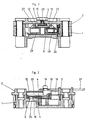
- FIG. 1 shows a housing base 1, in which three screwless conductor connecting terminals 24 I , 24 II , 24 III are preferably inserted with a clamping spring 25. Pressure leg 35, 36 of the clamping spring 25 clamp two connecting lead wires 37 in clamping grooves 38. The connecting line wires 37 can be released again by means of spring release buttons 39.
- Fixed contact parts 30, 31, 32 are inserted in contacting manner with plug-in tabs 23 in the conductor connection terminals 24.
- the plug-in lugs 23 preferably have beads 9, which serve for better locking of the respective plug-in lugs 23 in the housing wall of the conductor connection terminals 24.
- a contact rocker 10 is pivotally mounted on a contact rocker support point P of the first fixed contact part 30, which is designed as a rigid bearing contact, the pivot axis of the contact rocker 10 being perpendicular to Base floor of the housing base 1 is directed.
- the distance a I of the contact rocker support point P to the first conductor connection terminal 24 I is smaller than the distance a II of the contact rocker support point P to the second conductor connection terminal 24 II .
- a movable contact part 22 is arranged, which optionally and depending on the rocking position of the contact rocker 10 contacts either a second fixed contact part 31 or a third fixed contact part 32.
- the rocking position of the contact rocker 10 is controlled by a control cam 26 of a control rocker 8 pivotally mounted in the housing base 1.
- the control cam 26 is axially displaceable in a recess 29 of the control rocker 8 and resiliently supported by means of a control cam contact pressure spring 28.
- On the control rocker 8 two switching cams 27 are arranged, which are alternately switched by the engagement of two switching lugs 7 of a switching rocker 5.
- the rocker switch 5 is pivotally mounted on a slide switch 4 by means of a pivot bearing pin 6.
- the slide switch 4 can be moved linearly by means of a web 20 in a longitudinal groove 15 of an upper housing part 2.
- the slide switch 4 also has an integrally formed extension 13, on the end of which one end of a swivel slide return spring 3 is mounted laterally, the extension 13 resting on a first shoulder 17 of the housing base 1 and being mounted on a sliding bearing.
- a fastening pin 14 for an actuating pull cord 21 is attached on a part of the extension 13 which extends through a longitudinal recess 16 of the upper housing part 2, a fastening pin 14 for an actuating pull cord 21 is attached.
- Switch slide 4 and rocker switch 5 form a swivel slide 4, 5 that can be moved as well as swiveled.
- the rocker switch 5 rests on a second shoulder 18 of the housing base 1 and is slidingly supported.
- the switching mechanism of the electric pull switch described above is arranged on the housing base 1 in order to achieve a flat switch design in the plane of the contact parts.
- the housing base 1 is of central symmetry, that is to say that the housing base limiting points B 1, B 2 and the connecting base limiting lines b 1 2, B 2 1 connecting them are made to coincide by a 180 ° rotation about a point symmetry center M o .
Description
Die Erfindung betrifft einen elektrischen Zugschalter der im Oberbegriff des Anspruchs 1 genannten Art.The invention relates to an electric pull switch of the type mentioned in the preamble of
Mittels Zugschnüren betätigte Zugschalter sind im Stand der Technik in vielfältigen Ausführungen bekannt.Pull switches actuated by pull cords are known in the prior art in various designs.
So ist aus der DE-A- 19 11 129 ein elektrischer Zugschalter bekannt, dessen Schaltmechanik eine gegen eine Rückstellfeder gelagerte und spannbare Schaltwippe aufweist, welche über ein Filmscharnier mit einem in einer Längsnut des Gehäuseoberteils geführten Schaltschieber verbunden ist, an dem unmittelbar eine Zugschnur materialeinheitlich angeformt ist. Die Schaltwippe greift mit an gegenüberliegenden Seiten angeformten Schaltnasen an Schaltnocken einer Steuerwippe an, welche zentral gelagert ist und mit ihren freien, starre Steuernocken tragenden Enden Kontaktwippen von einer stabilen Lage in eine andere stabile Lage umschaltet.For example, from DE-A-19 11 129 an electric pull switch is known, the switching mechanism of which has a switch rocker which is mounted and can be tensioned against a return spring and which is connected via a film hinge to a slide switch guided in a longitudinal groove of the upper housing part, on which a pull cord is immediately made of the same material is molded. The switching rocker engages with switching lugs formed on opposite sides on switching cams of a control rocker, which is mounted centrally and with its free, rigid control cam-carrying ends, switches contact rockers from one stable position to another stable position.
Der im Stand der Technik bekannte Zugschalter, der mit vier als Schraubklemmen ausgebildeten Leiteranschlußklemmen ausgeführt ist, kann in eine 58er-UP-Wandeinbaudose nach DIN-Norm, sowie in eine UP-Wandeinbaudose nach CEE-Norm vorschriftsmäßig eingebaut werden. Der beim Einbau in eine CEE-Normdose vorgeschriebene Mindestabstand von a=6 mm zwischen der Dosenwand und spannungsführenden Teilen des Zugschalters kann dabei gewährleistet werden. Ebenso wird dabei im Bereich der Leiteranschlußklemmen einschließlich der dort angeschlossenen Leitungen das Sockelgrößtmaß gemäß CEE-Norm nicht überschritten.The pull switch known in the prior art, which is designed with four conductor terminals designed as screw terminals, can be installed in a 58 mm flush-mounting wall box according to DIN standard, as well as in a flush-mounted wall box according to CEE standard. The minimum distance of a = 6 mm between the box wall and the live parts of the pull switch required for installation in a CEE standard box can be guaranteed. Likewise, the largest base dimension according to the CEE standard is not exceeded in the area of the conductor terminals, including the cables connected there.
Ausgehend vom vorgenannten Stand der Technik ist es Aufgabe der Erfindung einen als flachbauenden UP-Schalter sowohl in eine UP-Wandeinbaudose nach DIN-Norm (φ = 58 mm) als auch in eine UP-Wandeinbaudose nach CEE-Norm einpaßbaren Zugschalter mit schraubenlosen Leiteranschlußklemmen und ausreichender Schaltleistung zu schaffen, bei welchem zwischen spannungsführenden Teilen und der CEE-Normdosenwand ein Abstand a ≧ 6 mm eingehalten ist und bei welchem alle spannungsführenden Teile, insbesondere Leiteranschlußklemmen nebst Anschlußleitungsdrähten, innerhalb eines nach CEE-Norm vorgeschriebenen Gehäusesockel-Größmaßes angeordnet sind.Starting from the aforementioned prior art, it is an object of the invention a pull switch with screwless conductor connection terminals and which can be fitted as a flat-type flush-mounted switch both into a flush-mounted wall mounting box according to DIN standard (φ = 58 mm) and into a flush-mounting wall box according to CEE standard To provide sufficient switching capacity, at which a distance of ≧ 6 mm is maintained between live parts and the CEE standard box wall and in which all live parts, in particular conductor connecting terminals along with connecting wires, are arranged within a housing base size specified in accordance with the CEE standard.
Diese Aufgabe wird durch die Merkmale des Anspruchs 1 in vorteilhafter Weise gelöst.This object is achieved in an advantageous manner by the features of
Durch die erfindungsgemäß zentralsymmetrische Ausbildung des Gehäusesockels ist eine vorschriftgemäße Einpassung des Zugschalters mit schraubenlosen Leiteranschlußklemmen nicht nur in eine DIN-Normdose, sondern auch in eine CEE-Normdose möglich. Hierbei werden die jeweils paarweise von oben oder von unten an die Anschlußklemmen herangeführten Anschlußleitungen seitlich in die generell für den Anschluß von zwei Anschlußleitungen vorgesehenen Anschlußklemmen eingeführt.Due to the central symmetrical design of the housing base according to the invention, a proper fitting of the pull switch with screwless conductor connection terminals is possible not only in a DIN standard socket but also in a CEE standard socket. In this case, the connecting lines brought in pairs from above or from below to the connecting terminals are laterally inserted into the connecting terminals generally provided for connecting two connecting lines.
Besonders vorteilhaft ist dabei, daß trotz der Bestückung des Gerätesockels mit im Vergleich zu Schraubklemmen relativ viel Raum beanspruchenden schraubenlosen Anschlußklemmen noch ein hinreichend großer Schaltraum für die Erzielung ausreichender Schaltleistung zur Verfügung steht. Hierzu trägt insbesondere bei, daß der neben der asymmetrischen Anordnung der ersten und zweiten Leiteranschlußklemme auch der zwischen der ersten und der zweiten schraubenlosen Leiteranschlußklemme sich befindliche Schaltraum erfindungsgemäß dadurch asymmetrisch aufgeteilt ist, daß der Abstand des Kontaktwippenauflagerpunktes zu der ersten Leiteranschlußklemme kleiner ist als der Abstand des Kontaktwippenauflagerpunktes zu der zweiten Leiteranschlußklemme.It is particularly advantageous that in spite of the fact that the device base is equipped with screwless connecting terminals which take up a relatively large amount of space in comparison to screw terminals, a sufficiently large switching space is still available for achieving sufficient switching power. This is particularly due to the fact that, in addition to the asymmetrical arrangement of the first and second conductor connection terminals, the switching space located between the first and the second screwless conductor connection terminal is also asymmetrically divided according to the invention in that the distance between the contact rocker support point and the first conductor connection terminal is smaller than the distance of the Contact rocker support point to the second conductor terminal.
Zudem ist es von Vorteil, daß zwecks Erreichung einer flachbauenden Schalterbauweise der Schaltmechanismus in der Ebene der Schaltkontakte und zwar zwischen diesen angeordnet ist.It is also advantageous that, in order to achieve a flat switch design, the switching mechanism is arranged in the plane of the switching contacts, namely between them.
In einer Ausführungsform als Wechselschalter ist der Zugschalter vorteilhafterweise nur mit drei Anschlußklemmen bestückt.In one embodiment as a changeover switch, the pull switch is advantageously only equipped with three connecting terminals.
In einer weiteren Ausführungsform als zweipoliger AUS-Schalter ist der erfindungsgemäße Zugsschalter mit vier schraubenlosen Anschlußklemmen bestückt.In a further embodiment as a two-pole OFF switch, the pull switch according to the invention is equipped with four screwless connecting terminals.
Die Erfindung soll nachfolgend anhand eines Ausführungsbeispiels eines Zug-Wechselschalters näher beschrieben und erläutert werden.The invention will be described and explained in more detail below using an exemplary embodiment of a train changeover switch.
Es zeigen:
Figur 1- Einen in eine Unterputz-Wandeinbaudose eingebauten erfindungsgemäßen Zugschalter in Aufsicht bei
abgenommenem Gehäuseoberteil 2, Figur 2- einen Querschnitt durch den erfindungsgemäßen elektrischen Zugschalter mit
Gehäuseoberteil 2 nach der Schnittlinie II-II inFigur 1, Figur 3- einen Querschnitt durch den erfindungsgemäßen elektrischen Zugschalter nach der Schnittlinie III-III in
Figur 1, Figur 4- einen Querschnitt durch den erfindungsgemäßen elektrischen Zugschalter nach Schnittlinie IV-IV in
Figur 1.
- Figure 1
- A pull switch according to the invention installed in a flush-mounted wall mounting box in supervision with the
upper housing part 2 removed, - Figure 2
- 2 shows a cross section through the electric pull switch according to the invention with the
upper housing part 2 along the section line II-II in FIG. 1, - Figure 3
- 2 shows a cross section through the electric pull switch according to the invention along the section line III-III in FIG. 1,
- Figure 4
- 2 shows a cross section through the electrical pull switch according to the invention along section line IV-IV in FIG. 1.
Figur 1 zeigt einen Gehäusesockel 1, in welchem vorzugsweise mit einer Klemmfeder 25 drei schraublos ausgebildete Leiteranschlußklemmen 24I, 24II, 24III einliegen. Druckschenkel 35,36 der Klemmfeder 25 klemmen jeweis zwei Anschlußleitungsdrähte 37 in Klemmnuten 38 fest. Die Anschlußleitungsdrähte 37 können mittels Klemmfederlösetasten 39 wieder gelöst werden. Ortsfeste Kontaktteile 30,31,32 sind mittels Steckfahnen 23 in die Leiteranschlußklemmen 24 kontaktierend eingesteckt. Die Steckfahnen 23 weisen vorzugsweise Sicken 9 auf, welche der besseren Verrastung der jeweiligen Steckfahne 23 in der Gehäusewand der Leiteranschlußklemmen 24 dienen. Eine Kontaktwippe 10 ist auf einem Kontaktwippenauflagerpunkt P des als starrer Lagerkontakt ausgebildeten ersten ortsfesten Kontaktteils 30 schwenkbar gelagert, wobei die Schwenkachse der Kontaktwippe 10 senkrecht zum Sockelboden des Gehäusesockels 1 gerichtet ist. Der Abstand aI des Kontaktwippenauflagerpunktes P zu der ersten Leiteranschlußklemme 24I ist kleiner als der Abstand aII des Kontaktwippenauflagerpunktes P zu der zweiten Leiteranschlußklemme 24II. An einem beweglichen Ende der Kontaktwippe 10 ist ein beweglicher Kontaktteil 22 angeordnet, welcher wahlweise und abhängig von der Wippstellung der Kontaktwippe 10 entweder einen zweiten ortsfesten Kontaktteil 31 oder einen dritten ortsfesten Kontaktteil 32 kontaktiert. Die Wippstellung der Kontaktwippe 10 wird durch einen Steuernocken 26 einer zentral im Gehäusesockel 1 schwenkbar gelagerten Steuerwippe 8 gesteuert. Der Steuernocken 26 ist in einer Ausnehmung 29 der Steuerwippe 8 axial verschiebbar und mit Hilfe einer Steuernocken-Kontaktdruckfeder 28 federnd gelagert. Auf der Steuerwippe 8 sind zwei Schaltnocken 27 angeordnet, welche durch den Eingriff zweier Schaltnasen 7 einer Schaltwippe 5 wechselweise geschaltet werden. Die Schaltwippe 5 ist mit Hilfe eines Schwenklagerzapfens 6 an einem Schaltschieber 4 schwenkbar gelagert. Der Schaltschieber 4 ist mittels eines Stegs 20 in einer Längsnut 15 eines Gehäuseoberteils 2 linear verfahrbar. Der Schaltschieber 4 weist außerdem einen angeformten Fortsatz 13 auf, an welchem endseitig lateral ein Ende einer Schwenkschieber-Rückstellfeder 3 gelagert ist, wobei der Fortsatz 13 auf einem ersten Absatz 17 des Gehäusesockels 1 aufliegt und gleitgelagert ist. Auf einem, eine Längsausnehmung 16 des Gehäuseoberteils 2 durchgreifenden Teil des Fortsatzes 13 ist ein Befestigungszapfen 14 für eine Betätigungszugschnur 21 angebracht. Schaltschieber 4 und Schaltwippe 5 bilden einen sowohl linear verfahrbaren als auch schwenkbaren Schwenkschieber 4,5. Die Schaltwippe 5 liegt auf einem zweiten Absatz 18 des Gehäusesockels 1 auf und ist gleitgelagert. Beide Flanken 11 von an der Schaltwippe 5 ausgeformten Schaltnasen 7 schlagen in einer Ruhestellung A an symmetrisch zur Verfahrbahn des Schaltschiebers 4 angeordneten Anschlägen 12 an. Hierdurch wird die Schaltwippe 5 nach jedem Schaltspiel in eine stabile Ausgangslage für den nachfolgenden Schaltvorgang gebracht.FIG. 1 shows a
Die vorstehend beschriebene Schaltmechanik des elektrischen Zugschalters ist zwecks Erreichung einer flachbauenden Schalterbauweise in der Ebene der Kontaktteile und zwar zwischen diesen auf dem Gehäusesockel 1 angeordnet. Der Gehäusesockel 1 ist zentralsymmetrisch ausgebildet, d. h., daß die Gehäusesockelbegrenzungspunkte B₁,B₂ nebst den sie verbindenden Gehäusesockelbegrenzungslinien b₁₂,b₂₁ durch eine 180°-Drehung um ein Punktsymmetriezentrum Mo zur Deckung gebracht werden. Durch diese Maßnahmen ist es gelungen, daß der im vorliegenden Ausführungsbeispiel eines Wechelschalters mit drei relativ viel Raum beanspruchenden schraubenlosen Anschlußklemmen 24I,24II,24III bestückte Gehäusesockel 1 in eine der CEE-Norm entsprechende UP-Wandeinbaudose eingepaßt werden kann, und daß mit dem erfindungsgemäßen Zugschalter gleichwohl hohe Schaltleistungen erreicht werden können.The switching mechanism of the electric pull switch described above is arranged on the
Claims (2)
- Electrical pull switch for installation in flush-mounted wall installation boxes which conform with the DIN Standard and the CEE Standard, having a housing upper part (2) and a housing base (1) which accommodates conductor connecting terminals (24), and having a switching mechanism which is arranged in the plane of the conductor connecting terminals (24) and has a contact rocker (10), characterized in that the housing base (1) which is fitted with screwless conductor connecting terminals (24I, 24II, 24III) is of centrally symmetrical construction, the housing base boundary points (B₁, B₂) being made to coincide with the housing base boundary lines (b₁₂, b₂₁) connecting them by rotation of the housing base (1) about a point-symmetry centre (Mo) with a rotation angle of φ = 180°, and in that the distance (aI) from one contact rocker supporting point (P) to the first conductor connecting terminal (24I) is less than the distance (aII) from the contact rocker supporting point (P) to the second conductor connecting terminal (24II).
- Electrical pull switch according to Claim 1, characterized in that three or four screwless conductor connecting terminals (24) are preferably arranged on the centrally symmetrical housing base (1).
Applications Claiming Priority (2)
| Application Number | Priority Date | Filing Date | Title |
|---|---|---|---|
| DE9002939U | 1990-03-15 | ||
| DE9002939U DE9002939U1 (en) | 1990-03-15 | 1990-03-15 |
Publications (2)
| Publication Number | Publication Date |
|---|---|
| EP0446842A1 EP0446842A1 (en) | 1991-09-18 |
| EP0446842B1 true EP0446842B1 (en) | 1994-08-31 |
Family
ID=6851922
Family Applications (1)
| Application Number | Title | Priority Date | Filing Date |
|---|---|---|---|
| EP91103699A Expired - Lifetime EP0446842B1 (en) | 1990-03-15 | 1991-03-11 | Electrical pull switch |
Country Status (2)
| Country | Link |
|---|---|
| EP (1) | EP0446842B1 (en) |
| DE (2) | DE9002939U1 (en) |
Family Cites Families (4)
| Publication number | Priority date | Publication date | Assignee | Title |
|---|---|---|---|---|
| NL110172C (en) * | 1958-02-27 | |||
| DE2646853A1 (en) * | 1976-10-16 | 1978-04-20 | Giersiepen Eltech Ind | Pull switch with contact rocker on knife edge - has rocking pull element hinged in switch socket which operates rest of switch |
| DE3214460A1 (en) * | 1982-04-20 | 1983-10-27 | Brown, Boveri & Cie Ag, 6800 Mannheim | Electromagnetic switching device with screwless terminal connecting bodies |
| FR2551913B1 (en) * | 1983-09-12 | 1986-10-03 | Legrand Sa | DRAFT CONTROL SWITCH AND DRAFT CONTROL HEAD FOR SUCH A SWITCH |
-
1990
- 1990-03-15 DE DE9002939U patent/DE9002939U1/de not_active Expired - Lifetime
-
1991
- 1991-03-11 EP EP91103699A patent/EP0446842B1/en not_active Expired - Lifetime
- 1991-03-11 DE DE59102679T patent/DE59102679D1/en not_active Expired - Fee Related
Also Published As
| Publication number | Publication date |
|---|---|
| DE59102679D1 (en) | 1994-10-06 |
| DE9002939U1 (en) | 1990-05-17 |
| EP0446842A1 (en) | 1991-09-18 |
Similar Documents
| Publication | Publication Date | Title |
|---|---|---|
| DE1665361A1 (en) | Power strip | |
| DE2505908A1 (en) | COUNTER | |
| AT517769A2 (en) | Energy meter connection block with lock-up device | |
| DE2833497C2 (en) | Electrical load switch for low-voltage systems | |
| DE19856678C2 (en) | Electrical switching device | |
| EP0000711A1 (en) | Contactor with readily accessible wire connecting terminals disposed at different levels | |
| EP0446842B1 (en) | Electrical pull switch | |
| DE19530947C2 (en) | Terminal block for electricity meters | |
| EP1673795B1 (en) | Contactor equipped with box terminals | |
| DE10055035C2 (en) | Switch disconnector with at least one fuse holder | |
| DE3620416C2 (en) | ||
| EP1356548B1 (en) | Contact device for the detachable connection of a mobile appliance unit to fixed conductor rails | |
| DE2548723B2 (en) | Multi-pole electrical switch with a slim design | |
| DE3825647C2 (en) | ||
| DE2622054C3 (en) | Electromagnetic switching device | |
| EP1296431A2 (en) | Bus bar assembly | |
| EP0310885B1 (en) | Electric switch gear | |
| DE8504297U1 (en) | Rotary switch unit for an electrical hand-held device | |
| DE19943734B4 (en) | Electrical installation plug connector with a phase selector | |
| WO2009030719A1 (en) | Switch having at least two switch levels | |
| DE2437509C2 (en) | Fuse disconnector | |
| DE10115708B4 (en) | Electrical switching device | |
| DE2737021C3 (en) | Isolation switch for low voltage | |
| DE3701246C2 (en) | ||
| EP0294653A1 (en) | Off-load tap changer for transformers |
Legal Events
| Date | Code | Title | Description |
|---|---|---|---|
| PUAI | Public reference made under article 153(3) epc to a published international application that has entered the european phase |
Free format text: ORIGINAL CODE: 0009012 |
|
| AK | Designated contracting states |
Kind code of ref document: A1 Designated state(s): BE DE NL |
|
| 17P | Request for examination filed |
Effective date: 19911008 |
|
| 17Q | First examination report despatched |
Effective date: 19940214 |
|
| GRAA | (expected) grant |
Free format text: ORIGINAL CODE: 0009210 |
|
| AK | Designated contracting states |
Kind code of ref document: B1 Designated state(s): BE DE NL |
|
| PG25 | Lapsed in a contracting state [announced via postgrant information from national office to epo] |
Ref country code: NL Effective date: 19940831 |
|
| REF | Corresponds to: |
Ref document number: 59102679 Country of ref document: DE Date of ref document: 19941006 |
|
| NLV1 | Nl: lapsed or annulled due to failure to fulfill the requirements of art. 29p and 29m of the patents act | ||
| PG25 | Lapsed in a contracting state [announced via postgrant information from national office to epo] |
Ref country code: BE Effective date: 19950331 |
|
| PLBE | No opposition filed within time limit |
Free format text: ORIGINAL CODE: 0009261 |
|
| STAA | Information on the status of an ep patent application or granted ep patent |
Free format text: STATUS: NO OPPOSITION FILED WITHIN TIME LIMIT |
|
| 26N | No opposition filed | ||
| BERE | Be: lapsed |
Owner name: ASEA BROWN BOVERI A.G. Effective date: 19950331 |
|
| PG25 | Lapsed in a contracting state [announced via postgrant information from national office to epo] |
Ref country code: DE Effective date: 19951201 |