EP0446526A2 - Differenzstromschutzschaltungen - Google Patents
Differenzstromschutzschaltungen Download PDFInfo
- Publication number
- EP0446526A2 EP0446526A2 EP90313703A EP90313703A EP0446526A2 EP 0446526 A2 EP0446526 A2 EP 0446526A2 EP 90313703 A EP90313703 A EP 90313703A EP 90313703 A EP90313703 A EP 90313703A EP 0446526 A2 EP0446526 A2 EP 0446526A2
- Authority
- EP
- European Patent Office
- Prior art keywords
- winding
- resistor
- protection circuit
- differential protection
- current transformer
- Prior art date
- Legal status (The legal status is an assumption and is not a legal conclusion. Google has not performed a legal analysis and makes no representation as to the accuracy of the status listed.)
- Withdrawn
Links
Images
Classifications
-
- G—PHYSICS
- G05—CONTROLLING; REGULATING
- G05B—CONTROL OR REGULATING SYSTEMS IN GENERAL; FUNCTIONAL ELEMENTS OF SUCH SYSTEMS; MONITORING OR TESTING ARRANGEMENTS FOR SUCH SYSTEMS OR ELEMENTS
- G05B11/00—Automatic controllers
-
- H—ELECTRICITY
- H02—GENERATION; CONVERSION OR DISTRIBUTION OF ELECTRIC POWER
- H02H—EMERGENCY PROTECTIVE CIRCUIT ARRANGEMENTS
- H02H3/00—Emergency protective circuit arrangements for automatic disconnection directly responsive to an undesired change from normal electric working condition with or without subsequent reconnection ; integrated protection
- H02H3/26—Emergency protective circuit arrangements for automatic disconnection directly responsive to an undesired change from normal electric working condition with or without subsequent reconnection ; integrated protection responsive to difference between voltages or between currents; responsive to phase angle between voltages or between currents
- H02H3/28—Emergency protective circuit arrangements for automatic disconnection directly responsive to an undesired change from normal electric working condition with or without subsequent reconnection ; integrated protection responsive to difference between voltages or between currents; responsive to phase angle between voltages or between currents involving comparison of the voltage or current values at two spaced portions of a single system, e.g. at opposite ends of one line, at input and output of apparatus
Definitions
- This invention relates generally to control circuits for use in combination with electric power systems, and particularly, to such control circuits which respond to a difference in current flow at different locations along a power conductor.
- Constant speed drive electric power systems which are typically found on commercial aircraft, couple an electric generator to the aircraft engine through a hydromechanical transmission which drives the generator at a constant speed to produce a constant frequency output voltage.
- Variable speed constant frequency (VSCF) power systems include a generator which is directly coupled to the engine and therefore driven at variable speeds. The variable frequency output of this generator is electronically converted to a constant frequency output. It is desirable to retrofit existing constant speed drive equipped aircraft with variable speed constant frequency power systems. A key to successful retrofit lies in the design of a VSCF system which is directly interchangeable with the existing constant speed drive system. This precludes aircraft wiring changes or changes in any of the other system components. To accomplish this objective, the VSCF converter and its controls must be in the same package as the generator and a remote generator control unit is positioned closer to the system loads.
- Differential protection circuits which monitor current at different locations in a power system and produce a control signal for de-exciting the voltage generating source when the difference in currents exceeds some predetermined value, are well known in the art.
- Typical differential protection circuits such as those in U.S. Patent No. 4,173,774, contain two current transformers which respond to electric current in a power conductor and are connected in a loop. At least one burden resistor is connected across the current transformers and the polarity of the voltage developed across the transformers is such that if the same current flows through both transformers, no voltage is developed across the burden resistor. If a fault occurs on the power conductor between the two transformers, a voltage is developed across the burden resistor.
- a control circuit detects the presence of this voltage and takes appropriate action by, for example, disabling the power source or disconnecting the power conductor from the load.
- a differential protection circuit for use in a VSCF aircraft power system that is used to replace a constant speed drive system must sense faults at both the VSCF system and the remote generator control unit. This sensing is complicated by the fact that the ground potential near the VSCF system may be different from the ground potential near the remote generator control unit because of common mode voltage in the aircraft structure. In addition, very high voltages can be introduced in the aircraft structure as a result of a lightning strike. It is therefore desirable to devise a differential protection circuit which can function in a VSCF system that is used to replace a constant speed drive system.
- a differential protection circuit constructed in accordance with this invention includes a pair of current transformers each having a secondary winding and being inductively coupled to a power conductor in the power system.
- the secondary windings are electrically connected in a loop in series with each other in a bucking arrangement.
- a resistor is electrically connected in parallel with each of the secondary windings.
- Control circuits are connected to receive a voltage signal developed across the resistor when a difference in current is sensed by the current transformers.
- One of the control circuits is isolated from the current transformer loop by using a separate winding on one of the current transformers. This eliminates false tripping that may result from a difference in potential of the system ground at the VSCF location and the system ground at the remote generator control unit location.
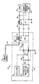
- a VSCF power system generally designated as item 10 comprises a power source 12, which includes a variable speed generator and converter for converting the generator output to a constant frequency AC output, and a generator control unit 14.
- the power source produces a constant frequency AC output voltage on a power conductor 16 in a multiple phase power bus, which is connected to a load 18 through a contactor 20.
- a local, or first, current transformer 22 is positioned near the power source to sense current in one of the conductors in the power bus 16, the current transformer includes a first secondary winding 24 and a second secondary winding 26.
- a first burden resistor 28 is connected across the secondary winding 24 of transformer 22.
- a second current transformer 30 is coupled to the same power conductor as the first current transformer and includes a first secondary winding 32.
- Burden resistor 34 is electrically connected across the secondary winding of transformer 30.
- Transformer windings 24 and 32 are electrically connected in series in a loop in a bucking arrangement such that if the same current flows in the power conductor, no voltage is produced across burden resistors 28 and 34. However, if a fault should occur between the current transformers, a voltage would be developed across the burden resistors.
- the voltage produced across resistor 34 would be sensed by a remote generator control unit 36, which includes control circuits constructed in accordance with known techniques, that would take appropriate action such as opening contactor 20 to remove the load from the power bus.
- the remote ground 38 may be at a potential which differs from the potential of the local ground 40, isolation is required between the differential protection circuit in the remote generator control unit 36 and the differential protection circuit 42 in the local generator control unit of the VSCF system. This isolation is provided by transformer winding 26. An additional resistor 44 and a diode 46 are electrically connected across winding 26. The diode converts an AC signal from winding 26 to a half wave DC signal for the sensing circuit in control unit 14. Feed-through capacitors 48 and 50 are positioned in an electromagnetic shield around the generator control unit 14.
- resistor 44 its resistance is significantly greater, for example, more than 100 times greater, than the resistance of resistor 28. Assuming that an equal number of turns is used to construct windings 24, 26 and 32, the voltage developed across winding 26 is equal to the voltage across resistor 28 plus the IR drop in winding 24. Thus, as the resistance of winding 24 is reduced, the voltage across the added winding approaches the voltage across the resistor 28. An analysis of the circuit has shown that for an acceptable worst case IR drop in winding 24 and the highest anticipated current in the power conductor, false tripping of the differential protection circuit 42 would not occur.
- an oscillator 52 which may be formed by using an existing microprocessor in the generator control unit to drive a transformer, is used to produce an AC signal at, for example, 12 kilohertz to cause the differential protection circuit in the remote generator control unit to trip the contactor 20.
- the 12 kilohertz frequency was chosen to be high enough to reduce the size of a transformer in the oscillator, yet low enough so that high frequency semiconductors are not required.
- the present invention avoids the use of a separate isolation transformer or other isolation devices such as differential amplifiers or optical couplers.
Landscapes
- Engineering & Computer Science (AREA)
- Power Engineering (AREA)
- Physics & Mathematics (AREA)
- General Physics & Mathematics (AREA)
- Automation & Control Theory (AREA)
- Emergency Protection Circuit Devices (AREA)
- Protection Of Static Devices (AREA)
- Regulation Of General Use Transformers (AREA)
Applications Claiming Priority (2)
| Application Number | Priority Date | Filing Date | Title |
|---|---|---|---|
| US491764 | 1990-03-12 | ||
| US07/491,764 US5047890A (en) | 1990-03-12 | 1990-03-12 | Differential current protection circuits |
Publications (2)
| Publication Number | Publication Date |
|---|---|
| EP0446526A2 true EP0446526A2 (de) | 1991-09-18 |
| EP0446526A3 EP0446526A3 (en) | 1992-08-05 |
Family
ID=23953567
Family Applications (1)
| Application Number | Title | Priority Date | Filing Date |
|---|---|---|---|
| EP19900313703 Withdrawn EP0446526A3 (en) | 1990-03-12 | 1990-12-14 | Differential current protection circuits |
Country Status (6)
| Country | Link |
|---|---|
| US (1) | US5047890A (de) |
| EP (1) | EP0446526A3 (de) |
| JP (1) | JPH04222417A (de) |
| KR (1) | KR910017253A (de) |
| CN (1) | CN1054856A (de) |
| CA (1) | CA2036181A1 (de) |
Families Citing this family (14)
| Publication number | Priority date | Publication date | Assignee | Title |
|---|---|---|---|---|
| US5523938A (en) * | 1995-06-07 | 1996-06-04 | Sundstrand Corporation | Differential current fault protection for an AC/DC hybrid system and method therefor |
| US5805394A (en) * | 1997-06-17 | 1998-09-08 | Sundstrand Corporation | Overvoltage protection circuit for a generating system utilizing a fault current sensing Circuit in combination with a shunting circuit |
| US6583975B2 (en) * | 2001-02-01 | 2003-06-24 | Hydro-Aire, Inc. | Aircraft applicable ground fault circuit interrupter |
| US7362551B2 (en) * | 2001-02-01 | 2008-04-22 | Hydro-Aire, Inc. | Aircraft applicable circuit imbalance detection and circuit interrupter and packaging thereof |
| US7016171B2 (en) | 2001-02-01 | 2006-03-21 | Hydro-Aire, Inc. | Current fault detector and circuit interrupter and packaging thereof |
| US6791852B2 (en) | 2001-12-28 | 2004-09-14 | General Electric Company | Method for detecting and identifying shorted thyristors |
| US6879224B2 (en) * | 2002-09-12 | 2005-04-12 | Agilent Technologies, Inc. | Integrated filter and impedance matching network |
| RU2244993C2 (ru) * | 2002-09-20 | 2005-01-20 | ОАО "Проектно-изыскательский и научно-исследовательский институт по проектированию энергетических систем и электрических сетей "Энергосетьпроект" | Устройство защиты от перенапряжений |
| CN100421326C (zh) * | 2003-05-28 | 2008-09-24 | 北京四方继保自动化有限公司 | 利用波形整形法进行差动保护的方法 |
| CN101218729B (zh) * | 2005-06-01 | 2010-06-16 | 立维腾制造有限公司 | 具有集成增强rfi抑制的电路中断装置 |
| US7928607B2 (en) * | 2007-03-29 | 2011-04-19 | Lamar Technologies Llc | Aircraft power system and apparatus for supplying power to an aircraft electrical system |
| RU2333583C1 (ru) * | 2007-04-26 | 2008-09-10 | Открытое Акционерное Общество "Проектно-изыскательский и научно-исследовательский институт по проектированию энергетических систем и электрических сетей" "Энергосетьпроект" | Способ контроля отказа выключателя |
| RU2399136C1 (ru) * | 2009-08-13 | 2010-09-10 | Открытое Акционерное Общество "Проектно-изыскательский и научно-исследовательский институт по проектированию энергетических систем и электрических сетей" ОАО "Институт "ЭНЕРГОСЕТЬПРОЕКТ" | Способ отключения короткого замыкания в электрической сети переменного тока высокого напряжения |
| CN102891473B (zh) * | 2012-09-24 | 2014-12-31 | 陕西航空电气有限责任公司 | 一种用于航空电源的电源系统差动保护方法 |
Family Cites Families (4)
| Publication number | Priority date | Publication date | Assignee | Title |
|---|---|---|---|---|
| US3294976A (en) * | 1964-02-27 | 1966-12-27 | Westinghouse Electric Corp | Unbalanced load detection in alternating current systems |
| US3539820A (en) * | 1968-01-10 | 1970-11-10 | Westinghouse Electric Corp | Real load unbalance protection circuit for alternating current power sources connected for parallel operation |
| US3683199A (en) * | 1970-09-14 | 1972-08-08 | Westinghouse Electric Corp | Over-{11 and underexcitation protection circuit for alternating current power systems |
| US4173774A (en) * | 1977-12-08 | 1979-11-06 | Westinghouse Electric Corp. | Parallel AC electrical system with differential protection immune to high current through faults |
-
1990
- 1990-03-12 US US07/491,764 patent/US5047890A/en not_active Expired - Fee Related
- 1990-12-14 EP EP19900313703 patent/EP0446526A3/en not_active Withdrawn
-
1991
- 1991-02-12 CA CA002036181A patent/CA2036181A1/en not_active Abandoned
- 1991-03-11 KR KR1019910003848A patent/KR910017253A/ko not_active Withdrawn
- 1991-03-11 CN CN91101447A patent/CN1054856A/zh active Pending
- 1991-03-12 JP JP3072537A patent/JPH04222417A/ja active Pending
Also Published As
| Publication number | Publication date |
|---|---|
| EP0446526A3 (en) | 1992-08-05 |
| US5047890A (en) | 1991-09-10 |
| JPH04222417A (ja) | 1992-08-12 |
| CN1054856A (zh) | 1991-09-25 |
| KR910017253A (ko) | 1991-11-05 |
| CA2036181A1 (en) | 1991-09-13 |
Similar Documents
| Publication | Publication Date | Title |
|---|---|---|
| US5047890A (en) | Differential current protection circuits | |
| US4383243A (en) | Powerline carrier control installation | |
| USRE30678E (en) | Dormant oscillator ground to neutral protection for ground fault interrupters | |
| EP0792007B1 (de) | Universeller Leistungsmodul | |
| US5570260A (en) | Overvoltage protection circuit | |
| EP0759220A1 (de) | Detektor zur überwachung der unversehrtheit einer erdverbindung eines elektrischen gerätes | |
| US20220107351A1 (en) | Apparatus and method for operating arc suppression coil | |
| SE510192C2 (sv) | Förfarande och kopplingsarrangemang för att minska problem med tredjetonsströmmar som kan uppstå vid generator - och motordrift av växelströmsmaskiner kopplade till trefas distributions- eller transmissionsnät | |
| US5262677A (en) | Reactor subsynchronous tuning scheme | |
| US6650523B1 (en) | Protective device, in particular a fault current protective device | |
| US5488303A (en) | GFCI with auxiliary coil current blocking means and improved test button configuration | |
| US4346422A (en) | Power-distribution network for telecommunication system | |
| EP0071484A1 (de) | Sekundärlichtbogenlöscheinrichtung | |
| US11862961B2 (en) | Apparatus and method for operating electric power network | |
| RU2157039C1 (ru) | Устройство контроля сопротивления изоляции и защиты электротехнической установки | |
| US3710188A (en) | High tension network distribution system | |
| WO1991020116A1 (en) | Low impedance power conditioner apparatus and method | |
| US6735063B1 (en) | Power circuit-breaker | |
| JPH0311921A (ja) | 地絡検出保護装置 | |
| RU1786581C (ru) | Устройство дл защиты сети переменного тока с компенсированой нейтралью при однофазном замыкании на землю | |
| Calkin et al. | SF system: Power conversion | |
| JP3237018B2 (ja) | 同期調相機の保護装置 | |
| SU801182A1 (ru) | Электрическа трехфазна сеть с устройст-BOM дл КОМпЕНСАции TOKA ОдНОфАзНОгО зАМы-КАНи HA зЕМлю | |
| RU1772859C (ru) | Датчик защиты электрической цепи переменного тока от перегрузки и обрыва | |
| JPH0549160A (ja) | スイツチング電源装置の保護回路 |
Legal Events
| Date | Code | Title | Description |
|---|---|---|---|
| PUAI | Public reference made under article 153(3) epc to a published international application that has entered the european phase |
Free format text: ORIGINAL CODE: 0009012 |
|
| AK | Designated contracting states |
Kind code of ref document: A2 Designated state(s): DE FR GB IT |
|
| PUAL | Search report despatched |
Free format text: ORIGINAL CODE: 0009013 |
|
| AK | Designated contracting states |
Kind code of ref document: A3 Designated state(s): DE FR GB IT |
|
| RAP1 | Party data changed (applicant data changed or rights of an application transferred) |
Owner name: SUNDSTRAND CORPORATION |
|
| STAA | Information on the status of an ep patent application or granted ep patent |
Free format text: STATUS: THE APPLICATION IS DEEMED TO BE WITHDRAWN |
|
| 18D | Application deemed to be withdrawn |
Effective date: 19930520 |