EP0445696A2 - Process for compacting waste materials and apparatus for performing the same - Google Patents
Process for compacting waste materials and apparatus for performing the same Download PDFInfo
- Publication number
- EP0445696A2 EP0445696A2 EP91103218A EP91103218A EP0445696A2 EP 0445696 A2 EP0445696 A2 EP 0445696A2 EP 91103218 A EP91103218 A EP 91103218A EP 91103218 A EP91103218 A EP 91103218A EP 0445696 A2 EP0445696 A2 EP 0445696A2
- Authority
- EP
- European Patent Office
- Prior art keywords
- materials
- compression
- compacted
- compaction
- waste materials
- Prior art date
- Legal status (The legal status is an assumption and is not a legal conclusion. Google has not performed a legal analysis and makes no representation as to the accuracy of the status listed.)
- Granted
Links
Images
Classifications
-
- B—PERFORMING OPERATIONS; TRANSPORTING
- B30—PRESSES
- B30B—PRESSES IN GENERAL
- B30B9/00—Presses specially adapted for particular purposes
- B30B9/02—Presses specially adapted for particular purposes for squeezing-out liquid from liquid-containing material, e.g. juice from fruits, oil from oil-containing material
- B30B9/20—Presses specially adapted for particular purposes for squeezing-out liquid from liquid-containing material, e.g. juice from fruits, oil from oil-containing material using rotary pressing members, other than worms or screws, e.g. rollers, rings, discs
-
- B—PERFORMING OPERATIONS; TRANSPORTING
- B09—DISPOSAL OF SOLID WASTE; RECLAMATION OF CONTAMINATED SOIL
- B09B—DISPOSAL OF SOLID WASTE
- B09B3/00—Destroying solid waste or transforming solid waste into something useful or harmless
- B09B3/20—Agglomeration, binding or encapsulation of solid waste
-
- B—PERFORMING OPERATIONS; TRANSPORTING
- B09—DISPOSAL OF SOLID WASTE; RECLAMATION OF CONTAMINATED SOIL
- B09B—DISPOSAL OF SOLID WASTE
- B09B3/00—Destroying solid waste or transforming solid waste into something useful or harmless
- B09B3/30—Destroying solid waste or transforming solid waste into something useful or harmless involving mechanical treatment
- B09B3/32—Compressing or compacting
-
- B—PERFORMING OPERATIONS; TRANSPORTING
- B30—PRESSES
- B30B—PRESSES IN GENERAL
- B30B9/00—Presses specially adapted for particular purposes
- B30B9/02—Presses specially adapted for particular purposes for squeezing-out liquid from liquid-containing material, e.g. juice from fruits, oil from oil-containing material
- B30B9/04—Presses specially adapted for particular purposes for squeezing-out liquid from liquid-containing material, e.g. juice from fruits, oil from oil-containing material using press rams
- B30B9/06—Presses specially adapted for particular purposes for squeezing-out liquid from liquid-containing material, e.g. juice from fruits, oil from oil-containing material using press rams co-operating with permeable casings or strainers
-
- B—PERFORMING OPERATIONS; TRANSPORTING
- B30—PRESSES
- B30B—PRESSES IN GENERAL
- B30B9/00—Presses specially adapted for particular purposes
- B30B9/30—Presses specially adapted for particular purposes for baling; Compression boxes therefor
- B30B9/3003—Details
- B30B9/3039—Fluid removing means
Definitions
- the present invention relates to a process for compacting waste materials, such as urban, industrial or similar waste materials and also special hospital waste and the like, etc., and to the apparatus for performing such process.
- the main structural-functional characteristic of the variations of the waste during compaction is constituted by the so-called “delayed liquid phase", which determines its tendency toward non-compactibility.
- the aim of the present invention is to provide a process for compacting urban, industrial or similar waste materials which can cause the manifestation of the delayed liquid phase and separate it from the compacted materials.
- a consequent primary object is to provide a process and an apparatus for performing it which do not have negative environmental impact aspects.
- Another important object is to provide a process and the related apparatus for its execution which have positive large-scale and wide-ranging induced effects in territorial, constructive, economical, environmental, ecological and social situations.
- Not least object is to solve the urgent problem currently constituted by the disposal of urban, industrial and special waste, and of urban, industrial, special hospital and similar sludge, etc.
- the apparatus for executing such process is characterized in that it comprises roller compression means arranged above scroll feeders suitable for unloading waste materials into containers which can slide on a transfer line, a compacting press being arranged at the beginning of said line, said line comprising, in succession, a heating tunnel, a cooling tunnel and finally a station for unloading the compacted elements.
- the waste materials after being unloaded into a container 1, are possibly pre-screened and pre-dried with hot air and are then loaded by means of a bridge crane 2 into a container 3 with a funnel-shaped bottom which is suitable for unloading them between a pair of parallel rotating rollers 4.
- the materials thus undergo a first compression and squeezing which separates a first liquid phase (the immediate liquid phase).
- the pre-compacted materials then fall into a hopper 5 which is arranged vertically, has a perforated bottom, and inside which a double converging variable-pitch mixing scroll 6 is arranged.
- the separation of the first liquid phase continues in said hopper 5; said phase is removed by means of a pipe 7 and discharged into a containment tank 8 provided with a related discharge gate valve.
- Said hopper 5 is arranged above a station on which a wheeled container 9 is located; said container can slide on a railed transfer line 10 and belongs to a series of containers of the same type which are aligned at mutually equal distances and are associated by chains 11; each container defines a self-compaction chamber.
- the transfer line 10 is conveniently closed in a loop, and the chain formed by the containers 9 is also closed in a loop.
- Each of said containers 9 is constituted by a strong metallic drum 12 with a cylindrical shape, with liquid discharge holes 12a on its bottom and with wheels 13 in a downward position.
- a shearing unit 14, arranged below the hopper 6, is activated; said shearing unit is suitable for separating the materials which, by virtue of the preceding treatments, are uniform and continuous.
- Said shearing unit 14 is substantially composed of a horizontal blade 15 which can slide on guides 16 and is actuated by a piston 17.
- each container 9 passes below a compacting press 18, the pressing part whereof comprises a lid 19 which is automatically fixed to the container at the end of compression by means of hooks 20 arranged at diametrically opposite positions.
- a piston 21 is arranged axially and is slidably associated with said lid 19, and discharge holes 22 extend from its pressing surface.
- Said piston 21 is suitable for maintaining a continuous pressure on the materials with which the container 9 has been filled.
- various layers of waste materials (preferably three), intercalated by appropriate flanges and always pressed by said piston 21, can be arranged inside each container 9.
- Cup-shaped springs 23 are conveniently arranged between the piston 21 and the lid 19 and are suitable for keeping the hooks 20 under tension and therefore for keeping the lid 19 rigidly associated with the drum 12.
- the hooks 20 can be released and the drum 12 can be freed from the piston 21.
- the separation of a second liquid phase occurs in this second compression step and in a subsequent heating step with compression in a self-compaction chamber.
- the heating step is performed by passing each container 9 inside a tunnel 24, conveniently with a raisable closure door 25, inside which a high temperature (by way of indication, 300/400 degrees Celsius) and a high pressure are maintained.
- each container 9 is passed through a tunnel 26 inside which sprays of cold water 27 cool said container 9 and therefore the compacted materials.
- An unloading station 29 is arranged at the exit of the tunnel 26 and comprises a piston 30 which arranges itself below each container 9 and, by entering in said container through a hole 31 of its bottom, causes a compacted block 32 to rise; by means of a horizontal piston 33 which is arranged above, said block is transferred onto a conveyor belt 34 which unloads it into a collection container 35.
- said drum has lateral tabs 36 which, when the container 9 is set in place, abut with other tabs 37 which are arranged above them and extend from the structure of the unloading station 29.
- the toxic and harmful elements are precipitated in the form of insoluble or scarcely soluble compounds and are subjected to an action of thermal destruction and inactivation, or are compacted and agglomerated in the mass, which can be subsequently wrapped with a protective covering.
- the compacted blocks can be reused as they are or with additives for the execution of structures such as embankments or other structures.
- the apparatus does not pollute the air, water or soil in any way; the liquid phases extruded as such or in vapor form are condensed and collected; from collection they pass to complete conditioning (or to other systems) with final emission of the water alone, since the conditioning waste is normally reintroduced into the compacted materials.
- the apparatus does not emit odors, and the compacted materials have no foul odors, are not unsightly, do not percolate, are sterilized and thermally detoxified, and are hard, stable and inert.
- the process, and therefore the apparatus entail no kind of combustion, and the heat increase (300-400 degrees Celsius) is performed in the complete absence of air and oxygen, with the consequent absence of any form of combustion.
- the apparatus can naturally also be mounted so as to be mobile on trucks or boats for ordinary activities or for emergencies and natural or accidental disasters.
- the materials employed for the apparatus and the dimensions may be any according to the requirements.
Abstract
Description
- The present invention relates to a process for compacting waste materials, such as urban, industrial or similar waste materials and also special hospital waste and the like, etc., and to the apparatus for performing such process.
- Compaction as a process for the disposal of urban, industrial or similar waste materials is currently not very widespread due to a series of technical and conceptual difficulties related to the difficulty in providing valid, effective, reliable and economical apparatuses.
- The technical and conceptual difficulties in experimentation, design and execution of waste compaction processes and apparatuses are many and differ from one another, but they can be substantially grouped within the scope of a single common denominator, which is constituted by the problem of the continuous variation of the physical and chemical characteristics of the waste being compacted.
- The main structural-functional characteristic of the variations of the waste during compaction is constituted by the so-called "delayed liquid phase", which determines its tendency toward non-compactibility.
- During a conventional compaction of waste, two phases are in fact distinguished with reference to the separation of the liquids:
- an immediate liquid phase, which manifests itself with the appearance of liquids when compaction begins;
- a delayed liquid phase, which follows the preceding phase and, if it is not caused to manifest itself, blocks the continuation of the compaction due to the principle of incompressibility of liquids.
- The aim of the present invention is to provide a process for compacting urban, industrial or similar waste materials which can cause the manifestation of the delayed liquid phase and separate it from the compacted materials.
- A consequent primary object is to provide a process and an apparatus for performing it which do not have negative environmental impact aspects.
- Another important object is to provide a process and the related apparatus for its execution which have positive large-scale and wide-ranging induced effects in territorial, constructive, economical, environmental, ecological and social situations.
- Not least object is to solve the urgent problem currently constituted by the disposal of urban, industrial and special waste, and of urban, industrial, special hospital and similar sludge, etc.
- This aim, these objects and others which will become apparent hereinafter are achieved by a process for compacting waste materials which comprises the steps of:
- performing at least one first compression of the waste materials with squeezing and separation of a first liquid phase;
- feeding self-compaction chambers with the compressed materials;
- performing at least one second compression of the materials in the self-compaction chamber, with separation of a second liquid phase;
- heating the compacted materials; and
- cooling the compacted materials.
- The apparatus for executing such process is characterized in that it comprises roller compression means arranged above scroll feeders suitable for unloading waste materials into containers which can slide on a transfer line, a compacting press being arranged at the beginning of said line, said line comprising, in succession, a heating tunnel, a cooling tunnel and finally a station for unloading the compacted elements.
- Further characteristics and advantages of the invention will become apparent from the detailed description of the operating steps of the process and of an embodiment of the apparatus for its execution, which are given by way of non-limitative example.
- The apparatus for the execution of the process is illustrated, again by way of non-limitative example, in the accompanying drawings, wherein:
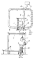
- figure 1 is a schematic top view of the apparatus;
- figure 2 is a side view of the region of the apparatus which is assigned to the loading of the materials to be compacted and to the unloading of the compacted materials;
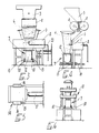
- figures 3 and 4 are side views of the section of the apparatus which is assigned to the first compression of the materials;
- figure 5 is a top detail view of a shearing unit arranged below the feeding means of the compaction containers;
- figure 6 is a view of the compaction press arranged after the container filling region;
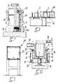
- figure 7 is a sectional view of the pressing means;
- figure 8 is a view of the apparatus in the inlet region of the heating tunnel;
- figure 9 is a front view of the inlet of the heating tunnel;
- figure 10 is a sectional detail view of the station for unloading the compacted materials.
- With reference to the above figures, the waste materials, after being unloaded into a container 1, are possibly pre-screened and pre-dried with hot air and are then loaded by means of a
bridge crane 2 into acontainer 3 with a funnel-shaped bottom which is suitable for unloading them between a pair of parallel rotatingrollers 4. - The materials thus undergo a first compression and squeezing which separates a first liquid phase (the immediate liquid phase).
- The pre-compacted materials then fall into a
hopper 5 which is arranged vertically, has a perforated bottom, and inside which a double converging variable-pitch mixing scroll 6 is arranged. - The separation of the first liquid phase continues in said
hopper 5; said phase is removed by means of a pipe 7 and discharged into acontainment tank 8 provided with a related discharge gate valve. - Said
hopper 5 is arranged above a station on which awheeled container 9 is located; said container can slide on a railedtransfer line 10 and belongs to a series of containers of the same type which are aligned at mutually equal distances and are associated by chains 11; each container defines a self-compaction chamber. - As can be seen in figure 1, the
transfer line 10 is conveniently closed in a loop, and the chain formed by thecontainers 9 is also closed in a loop. - Each of said
containers 9 is constituted by a strongmetallic drum 12 with a cylindrical shape, withliquid discharge holes 12a on its bottom and withwheels 13 in a downward position. - When each
container 9 which is waiting below thehopper 5 is filled, ashearing unit 14, arranged below thehopper 6, is activated; said shearing unit is suitable for separating the materials which, by virtue of the preceding treatments, are uniform and continuous. - Said shearing
unit 14 is substantially composed of ahorizontal blade 15 which can slide onguides 16 and is actuated by apiston 17. - After filling, each
container 9 passes below a compactingpress 18, the pressing part whereof comprises a lid 19 which is automatically fixed to the container at the end of compression by means ofhooks 20 arranged at diametrically opposite positions. - A
piston 21 is arranged axially and is slidably associated with said lid 19, anddischarge holes 22 extend from its pressing surface. - Said
piston 21 is suitable for maintaining a continuous pressure on the materials with which thecontainer 9 has been filled. - Alternatively, various layers of waste materials (preferably three), intercalated by appropriate flanges and always pressed by said
piston 21, can be arranged inside eachcontainer 9. - Cup-
shaped springs 23 are conveniently arranged between thepiston 21 and the lid 19 and are suitable for keeping thehooks 20 under tension and therefore for keeping the lid 19 rigidly associated with thedrum 12. - By subsequently exerting a compression on the lid 19 in contrast with the action of the cup-
shaped springs 23, thehooks 20 can be released and thedrum 12 can be freed from thepiston 21. - The separation of a second liquid phase (the delayed liquid phase) occurs in this second compression step and in a subsequent heating step with compression in a self-compaction chamber.
- The heating step is performed by passing each
container 9 inside atunnel 24, conveniently with araisable closure door 25, inside which a high temperature (by way of indication, 300/400 degrees Celsius) and a high pressure are maintained. - This allows the further evaporation of the liquids still contained in the compacted materials.
- After the heating step, each
container 9 is passed through atunnel 26 inside which sprays ofcold water 27 cool saidcontainer 9 and therefore the compacted materials. - An
unloading station 29 is arranged at the exit of thetunnel 26 and comprises apiston 30 which arranges itself below eachcontainer 9 and, by entering in said container through ahole 31 of its bottom, causes a compacted block 32 to rise; by means of ahorizontal piston 33 which is arranged above, said block is transferred onto aconveyor belt 34 which unloads it into acollection container 35. - In order to prevent the action of the
piston 30 from also raising thedrum 12 due to adhesion of the compacted block 32 to the bottom, said drum haslateral tabs 36 which, when thecontainer 9 is set in place, abut withother tabs 37 which are arranged above them and extend from the structure of theunloading station 29. - The above described process and the apparatus for its execution produce a division of the compaction actions which is aimed at achieving the complete separation of the immediate and delayed liquid phases.
- A complete dehumidification and dehydration of the compacted materials is thus obtained, achieving a considerable reduction of the volume of the mass.
- The complete elimination of the liquid phase from the compacted materials allows to stabilize said materials from a physical and chemical point of view.
- It should furthermore be noted that the compaction action, combined with the thermal action, disinfects and disinfests the compacted materials.
- The toxic and harmful elements are precipitated in the form of insoluble or scarcely soluble compounds and are subjected to an action of thermal destruction and inactivation, or are compacted and agglomerated in the mass, which can be subsequently wrapped with a protective covering.
- The compacted blocks can be reused as they are or with additives for the execution of structures such as embankments or other structures.
- As regards the order of magnitude of the volume and weight reductions obtained with the process according to the invention, it is possible to achieve, by way of indication, reductions of 16-17 times by volume with respect to the original and of 30% by weight.
- As regards environmental impact problems, the apparatus does not pollute the air, water or soil in any way; the liquid phases extruded as such or in vapor form are condensed and collected; from collection they pass to complete conditioning (or to other systems) with final emission of the water alone, since the conditioning waste is normally reintroduced into the compacted materials.
- No gases or other air pollutants furthermore escape from the apparatus, not merely according to the statutory provisions, which provide for maximum allowable concentrations (as for incinerators, exhausts, etc.) and therefore according to a relative criterion (concentrations), but in absolute terms.
- The apparatus does not emit odors, and the compacted materials have no foul odors, are not unsightly, do not percolate, are sterilized and thermally detoxified, and are hard, stable and inert.
- The process, and therefore the apparatus, entail no kind of combustion, and the heat increase (300-400 degrees Celsius) is performed in the complete absence of air and oxygen, with the consequent absence of any form of combustion.
- The products resulting from compaction are in no way polluting, are compact, stable, dry, highly resistant to ordinary chemical-physical agents, highly resistant to compression and to other mechanical parameters, practically dehydrated and cannot be used as food for animals and parasites.
- Other positive effects related to the execution of the process according to the invention are constituted by an improvement in the general conditions of landfills, by the decrease in the number of landfills required and in their capacity, by the possibility of eliminating landfills, since the compacted materials can be reused both as they are and with additives, as previously mentioned, for foundations, reclamations, embankments, roads, etc.
- Other positive aspects consist in reducing the need for breaking up and ruining the territory for excavations and for destructions of the balances of the earth's surface to produce construction materials: gravel, sand, etc.; equivalent amounts of material for suitable purposes can be provided by the compacted materials.
- Finally, it should be furthermore noted that the disposal of waste can even be performed on-site by providing small apparatuses.
- The apparatus can naturally also be mounted so as to be mobile on trucks or boats for ordinary activities or for emergencies and natural or accidental disasters.
- In practice it has thus been observed that the invention has achieved the intended aim and objects.
- The invention thus conceived is susceptible to numerous modifications and variations, all of which are within the scope of the inventive concept.
- All the details may furthermore be replaced with other technically equivalent elements.
- The process as described is susceptible to further modifications and integrations without thereby abandoning the scope of the protection of the invention.
- In practice, the materials employed for the apparatus and the dimensions may be any according to the requirements.
- Where technical features mentioned in any claim are followed by reference signs, those reference signs have been included for the sole purpose of increasing the intelligibility of the claims and accordingly, such reference signs do not have any limiting effect on the scope of each element identified by way of example by such reference signs.
Claims (20)
- Process for compacting waste materials, in particular urban, industrial or similar waste materials, characterized in that it comprises the steps of:- performing at least one first compression of the waste materials with squeezing and separation of a first liquid phase;- feeding self-compaction chambers with the compressed materials;- performing at least one second compression of the materials in a self-compaction chamber, with separation of a second liquid phase;- heating the compacted materials; and- cooling the compacted materials.
- Apparatus for compacting waste materials, characterized in that it comprises roller compression means (4) arranged above scroll feeders (5) suitable for unloading the materials into containers (9) which can slide on a transfer line (10), a compacting press (18) being arranged at the beginning of said line, said line comprising, in succession, a heating tunnel (24), a cooling tunnel (26) and finally a station (29) for unloading the compacted elements.
- Process according to claim 1, characterized in that said first compression is preceded by a pre-screening and by a pre-drying, preferably with hot air.
- Process according to claim 1, characterized in that it comprises at least two distinct compression steps.
- Process according to claim 1, characterized in that the heating of the compacted materials occurs at high pressure with a thermal increase preferably to 300/400 degrees Celsius.
- Process according to claim 1, characterized in that said second compression occurs in self-compaction chambers (9) which are distinct from a compacting press (4) at which takes place said first compression.
- Process according to claims 1 and 5, characterized in that the compression action in the self-compaction chamber (9) is continuous.
- Process according to claim 1, characterized in that it combines a compaction compression in a self-compaction chamber (9) with a thermal action.
- Apparatus according to claim 2, characterized in that said roller compression means are constituted by a pair of parallel motorized rollers (4) through which the waste materials, loaded in a container (6) with a shaped and perforated bottom, are passed.
- Apparatus according to claim 2, characterized in that said scroll feeders (5) comprise a hopper (6) which is arranged below said roller compression means (4), a variable-pitch double converging scroll (5) being arranged in said hopper (6).
- Apparatus according to claims 2 and 9, characterized in that said hopper (6) is connected by means of a pipe to a tank for collecting said first liquid phase.
- Apparatus according to claims 2 and 5, characterized in that below said hopper (6) there is a shearing unit (14) suitable for shearing the materials after the filling of each of said sliding containers (9).
- Apparatus according to claim 2, characterized in that each of said sliding containers (9) which constitute said self-compaction chambers comprises a drum (12) which is provided, in a downward position, with wheels (13) which can slide on rails (10) which form said transfer line, appropriately in a loop, said containers (9) being aligned and equally spaced from one another and being associated by chains (11).
- Apparatus according to claims 2 and 8, characterized in that the bottom of said drums (12) has liquid discharge holes (12a) and an axial hole (31) with a considerable diameter.
- Apparatus according to claim 2, characterized in that the pressing part of said compacting press (18) comprises a lid (19) which can be associated by means of hooks (20) with each of said drums (9), said lid (19) having a compaction piston (21) slidably associated in an axial position, liquid discharge holes (22) extending in the pressing surface of said piston (21), elastic means, such as for example cup-shaped springs (23), being interposed between said piston (21) and said lid (19).
- Apparatus according to claims 2 and 12 to 14, characterized in that appropriate flanges, to be intercalated with various layers of waste materials, can be arranged inside said containers (9).
- Apparatus according to claim 2, characterized in that said heating tunnel (24) is kept internally at a high temperature and at a high pressure.
- Apparatus according to claim 2, characterized in that the cooling action is performed by sprays of cold water (27) in said cooling tunnel (26).
- Apparatus according to claim 2, characterized in that said unloading station (29) comprises a lower piston (30) which is suitable for penetrating inside each one of said containers (9) through said axial hole (31) of the bottom, lifting the compacted materials (32), and a substantially horizontal upper piston (33) which is suitable for pushing the compacted materials onto a conveyor belt (34) which unloads them into a collection chamber (35).
- Apparatus according to one or more of the preceding claims, characterized in that the materials to be compacted are loaded by means of a bridge crane (2) from a waste collection container (1).
Applications Claiming Priority (2)
| Application Number | Priority Date | Filing Date | Title |
|---|---|---|---|
| IT41548A IT1238836B (en) | 1990-03-05 | 1990-03-05 | PROCEDURE FOR THE COMPACTION OF URBAN, INDUSTRIAL OR SIMILAR WASTE MATERIALS AND PLANT FOR IMPLEMENTING THE PROCEDURE |
| IT4154890 | 1990-03-05 |
Publications (3)
| Publication Number | Publication Date |
|---|---|
| EP0445696A2 true EP0445696A2 (en) | 1991-09-11 |
| EP0445696A3 EP0445696A3 (en) | 1992-04-01 |
| EP0445696B1 EP0445696B1 (en) | 1994-11-30 |
Family
ID=11251001
Family Applications (1)
| Application Number | Title | Priority Date | Filing Date |
|---|---|---|---|
| EP91103218A Expired - Lifetime EP0445696B1 (en) | 1990-03-05 | 1991-03-04 | Process for compacting waste materials and apparatus for performing the same |
Country Status (9)
| Country | Link |
|---|---|
| EP (1) | EP0445696B1 (en) |
| JP (1) | JPH04222681A (en) |
| AT (1) | ATE114550T1 (en) |
| CA (1) | CA2037442A1 (en) |
| DE (1) | DE69105303D1 (en) |
| FI (1) | FI911006A (en) |
| IT (1) | IT1238836B (en) |
| NO (1) | NO910845L (en) |
| RU (1) | RU2038876C1 (en) |
Cited By (6)
| Publication number | Priority date | Publication date | Assignee | Title |
|---|---|---|---|---|
| ES2070767A2 (en) * | 1993-07-16 | 1995-06-01 | Imabe Iberica S A | System and installation for the treatment of urban solid waste |
| EP0671224A1 (en) * | 1994-03-08 | 1995-09-13 | Elio Castelli | Process for treating urban solid waste, and apparatus for performing it |
| ES2201848A1 (en) * | 2000-09-20 | 2004-03-16 | Imabe Iberica, S.A. | System and installation for the treatment of urban solid waste. (Machine-translation by Google Translate, not legally binding) |
| WO2006097952A1 (en) * | 2005-03-15 | 2006-09-21 | Gianpiero Contursi | Household appliance for organic waste disposal |
| GB2426004A (en) * | 2005-05-13 | 2006-11-15 | Design Build And Recycle Ltd | Process for treating waste |
| ES2380745A1 (en) * | 2009-12-30 | 2012-05-18 | Imabe Iberica S.A. | Machine for the pre-treatment of rejects of solid urban waste (Machine-translation by Google Translate, not legally binding) |
Citations (5)
| Publication number | Priority date | Publication date | Assignee | Title |
|---|---|---|---|---|
| GB924827A (en) * | 1961-06-30 | 1963-05-01 | Us Rubber Co | Process and means for baling particulate material |
| DE2235975A1 (en) * | 1971-07-21 | 1973-02-01 | Nat Res Dev | METHOD AND DEVICE FOR THE PRODUCTION OF SHAPED OBJECTS FROM FIBEROUS AND MINERAL INDUSTRIAL WASTE MATERIALS |
| EP0016734A1 (en) * | 1979-03-27 | 1980-10-01 | Eugène M.A. Baikoff | Process for separately compressing refuse, apparatus for carrying out this process |
| EP0202605A1 (en) * | 1985-05-21 | 1986-11-26 | Alsthom | Press for compacting waste materials |
| DE3804826A1 (en) * | 1988-02-17 | 1989-08-31 | Dietrich Kleinschmidt | Integrated process and apparatus for immobilising pollutants in waste materials |
-
1990
- 1990-03-05 IT IT41548A patent/IT1238836B/en active IP Right Grant
-
1991
- 1991-02-28 FI FI911006A patent/FI911006A/en not_active Application Discontinuation
- 1991-03-01 CA CA002037442A patent/CA2037442A1/en not_active Abandoned
- 1991-03-04 DE DE69105303T patent/DE69105303D1/en not_active Expired - Lifetime
- 1991-03-04 AT AT91103218T patent/ATE114550T1/en not_active IP Right Cessation
- 1991-03-04 EP EP91103218A patent/EP0445696B1/en not_active Expired - Lifetime
- 1991-03-04 NO NO91910845A patent/NO910845L/en unknown
- 1991-03-05 JP JP3062451A patent/JPH04222681A/en active Pending
- 1991-03-05 RU SU914894978A patent/RU2038876C1/en active
Patent Citations (5)
| Publication number | Priority date | Publication date | Assignee | Title |
|---|---|---|---|---|
| GB924827A (en) * | 1961-06-30 | 1963-05-01 | Us Rubber Co | Process and means for baling particulate material |
| DE2235975A1 (en) * | 1971-07-21 | 1973-02-01 | Nat Res Dev | METHOD AND DEVICE FOR THE PRODUCTION OF SHAPED OBJECTS FROM FIBEROUS AND MINERAL INDUSTRIAL WASTE MATERIALS |
| EP0016734A1 (en) * | 1979-03-27 | 1980-10-01 | Eugène M.A. Baikoff | Process for separately compressing refuse, apparatus for carrying out this process |
| EP0202605A1 (en) * | 1985-05-21 | 1986-11-26 | Alsthom | Press for compacting waste materials |
| DE3804826A1 (en) * | 1988-02-17 | 1989-08-31 | Dietrich Kleinschmidt | Integrated process and apparatus for immobilising pollutants in waste materials |
Cited By (6)
| Publication number | Priority date | Publication date | Assignee | Title |
|---|---|---|---|---|
| ES2070767A2 (en) * | 1993-07-16 | 1995-06-01 | Imabe Iberica S A | System and installation for the treatment of urban solid waste |
| EP0671224A1 (en) * | 1994-03-08 | 1995-09-13 | Elio Castelli | Process for treating urban solid waste, and apparatus for performing it |
| ES2201848A1 (en) * | 2000-09-20 | 2004-03-16 | Imabe Iberica, S.A. | System and installation for the treatment of urban solid waste. (Machine-translation by Google Translate, not legally binding) |
| WO2006097952A1 (en) * | 2005-03-15 | 2006-09-21 | Gianpiero Contursi | Household appliance for organic waste disposal |
| GB2426004A (en) * | 2005-05-13 | 2006-11-15 | Design Build And Recycle Ltd | Process for treating waste |
| ES2380745A1 (en) * | 2009-12-30 | 2012-05-18 | Imabe Iberica S.A. | Machine for the pre-treatment of rejects of solid urban waste (Machine-translation by Google Translate, not legally binding) |
Also Published As
| Publication number | Publication date |
|---|---|
| NO910845D0 (en) | 1991-03-04 |
| NO910845L (en) | 1991-09-06 |
| EP0445696B1 (en) | 1994-11-30 |
| DE69105303D1 (en) | 1995-01-12 |
| IT1238836B (en) | 1993-09-03 |
| JPH04222681A (en) | 1992-08-12 |
| FI911006A (en) | 1991-09-06 |
| IT9041548A0 (en) | 1990-03-05 |
| CA2037442A1 (en) | 1991-09-06 |
| RU2038876C1 (en) | 1995-07-09 |
| IT9041548A1 (en) | 1991-09-05 |
| EP0445696A3 (en) | 1992-04-01 |
| ATE114550T1 (en) | 1994-12-15 |
| FI911006A0 (en) | 1991-02-28 |
Similar Documents
| Publication | Publication Date | Title |
|---|---|---|
| US5460085A (en) | Process for compacting waste materials | |
| US5649785A (en) | Method of treating solid waste, recovering the constituent materials for recycling and reuse, and producing useful products therefrom | |
| US6692544B1 (en) | Municipal waste briquetting system and method of filling land | |
| US3752059A (en) | Method for treating household refuse | |
| EP0373460B1 (en) | Method of dumping waste | |
| US4587022A (en) | Process for dewatering sludge | |
| US20080048059A1 (en) | System and Method for Processing Waste on a Continuous Basis | |
| EP0445696B1 (en) | Process for compacting waste materials and apparatus for performing the same | |
| EP1502667A1 (en) | Municipal waste briquetting system and method of filling land | |
| EP0693979A1 (en) | Method of treating solid waste | |
| JP2002501432A (en) | Method for low-temperature conversion of municipal waste and / or sludge to inert material, equipment for carrying out the method and product obtained | |
| EP0671224B1 (en) | Process for treating urban solid waste, and apparatus for performing it | |
| US5582572A (en) | Method and plant for rendering solid waste inert and for its subsequent definite storage | |
| CN107199728B (en) | A kind of method that combustible compression is packaged | |
| CN106477834A (en) | A kind of processing equipment for the old mud soil remediation of simple landfill and its technique | |
| CN206279062U (en) | A kind of processing equipment and its technique for simply filling old sludge soil remediation | |
| US10683224B2 (en) | Sludge separation device and method for its use | |
| WO1993015842A1 (en) | Process and plant for treatment of household waste by physico-chemical and thermic means | |
| JPH0739857A (en) | Apparatus and method for producing soil and water quality improving material by utilizing carbonizable waste such as living garbage | |
| JPS5839594B2 (en) | Garbage processing method and equipment | |
| KR19990046466A (en) | Recyling process unit of purification plant sludge | |
| CN116729864A (en) | Portable garbage disposal emergency vehicle that kills | |
| CN110451121A (en) | A kind of house refuse feed bin and refuse disposal system | |
| Van der Wegen | Testmethods and criteria for the assessment of immobilized waste | |
| EP1841589A1 (en) | System and method for processing waste on a continuous basis |
Legal Events
| Date | Code | Title | Description |
|---|---|---|---|
| PUAI | Public reference made under article 153(3) epc to a published international application that has entered the european phase |
Free format text: ORIGINAL CODE: 0009012 |
|
| AK | Designated contracting states |
Kind code of ref document: A2 Designated state(s): AT BE CH DE DK ES FR GB GR LI LU NL SE |
|
| PUAL | Search report despatched |
Free format text: ORIGINAL CODE: 0009013 |
|
| AK | Designated contracting states |
Kind code of ref document: A3 Designated state(s): AT BE CH DE DK ES FR GB GR LI LU NL SE |
|
| 17P | Request for examination filed |
Effective date: 19920923 |
|
| 17Q | First examination report despatched |
Effective date: 19940119 |
|
| RAP3 | Party data changed (applicant data changed or rights of an application transferred) |
Owner name: ODORICO, ANGELO Owner name: CAPPELLARI, ROBERTO |
|
| GRAA | (expected) grant |
Free format text: ORIGINAL CODE: 0009210 |
|
| AK | Designated contracting states |
Kind code of ref document: B1 Designated state(s): AT BE CH DE DK ES FR GB GR LI LU NL SE |
|
| PG25 | Lapsed in a contracting state [announced via postgrant information from national office to epo] |
Ref country code: NL Effective date: 19941130 Ref country code: GR Free format text: LAPSE BECAUSE OF FAILURE TO SUBMIT A TRANSLATION OF THE DESCRIPTION OR TO PAY THE FEE WITHIN THE PRESCRIBED TIME-LIMIT Effective date: 19941130 Ref country code: FR Effective date: 19941130 Ref country code: ES Free format text: THE PATENT HAS BEEN ANNULLED BY A DECISION OF A NATIONAL AUTHORITY Effective date: 19941130 Ref country code: DK Effective date: 19941130 Ref country code: BE Effective date: 19941130 Ref country code: AT Effective date: 19941130 |
|
| REF | Corresponds to: |
Ref document number: 114550 Country of ref document: AT Date of ref document: 19941215 Kind code of ref document: T |
|
| REF | Corresponds to: |
Ref document number: 69105303 Country of ref document: DE Date of ref document: 19950112 |
|
| PG25 | Lapsed in a contracting state [announced via postgrant information from national office to epo] |
Ref country code: SE Effective date: 19950228 |
|
| PG25 | Lapsed in a contracting state [announced via postgrant information from national office to epo] |
Ref country code: DE Effective date: 19950301 |
|
| PG25 | Lapsed in a contracting state [announced via postgrant information from national office to epo] |
Ref country code: GB Effective date: 19950304 |
|
| PG25 | Lapsed in a contracting state [announced via postgrant information from national office to epo] |
Ref country code: LU Free format text: LAPSE BECAUSE OF NON-PAYMENT OF DUE FEES Effective date: 19950331 |
|
| EN | Fr: translation not filed | ||
| NLV1 | Nl: lapsed or annulled due to failure to fulfill the requirements of art. 29p and 29m of the patents act | ||
| PLBE | No opposition filed within time limit |
Free format text: ORIGINAL CODE: 0009261 |
|
| STAA | Information on the status of an ep patent application or granted ep patent |
Free format text: STATUS: NO OPPOSITION FILED WITHIN TIME LIMIT |
|
| GBPC | Gb: european patent ceased through non-payment of renewal fee |
Effective date: 19950304 |
|
| 26N | No opposition filed | ||
| PGFP | Annual fee paid to national office [announced via postgrant information from national office to epo] |
Ref country code: CH Payment date: 19970320 Year of fee payment: 7 |
|
| REG | Reference to a national code |
Ref country code: CH Ref legal event code: NV Representative=s name: MARK-PAT MODIANO S.A. |
|
| PG25 | Lapsed in a contracting state [announced via postgrant information from national office to epo] |
Ref country code: LI Free format text: LAPSE BECAUSE OF NON-PAYMENT OF DUE FEES Effective date: 19980331 Ref country code: CH Free format text: LAPSE BECAUSE OF NON-PAYMENT OF DUE FEES Effective date: 19980331 |
|
| REG | Reference to a national code |
Ref country code: CH Ref legal event code: PL |