EP0445211B1 - Methods for producing slush - Google Patents
Methods for producing slush Download PDFInfo
- Publication number
- EP0445211B1 EP0445211B1 EP90900502A EP90900502A EP0445211B1 EP 0445211 B1 EP0445211 B1 EP 0445211B1 EP 90900502 A EP90900502 A EP 90900502A EP 90900502 A EP90900502 A EP 90900502A EP 0445211 B1 EP0445211 B1 EP 0445211B1
- Authority
- EP
- European Patent Office
- Prior art keywords
- slush
- heat exchanger
- liquid
- water
- refrigerant
- Prior art date
- Legal status (The legal status is an assumption and is not a legal conclusion. Google has not performed a legal analysis and makes no representation as to the accuracy of the status listed.)
- Expired - Lifetime
Links
- 238000000034 method Methods 0.000 title claims abstract description 26
- 239000007788 liquid Substances 0.000 claims abstract description 60
- XLYOFNOQVPJJNP-UHFFFAOYSA-N water Substances O XLYOFNOQVPJJNP-UHFFFAOYSA-N 0.000 claims description 51
- 239000003507 refrigerant Substances 0.000 claims description 26
- 239000003792 electrolyte Substances 0.000 claims description 22
- 239000000203 mixture Substances 0.000 claims description 20
- 239000013078 crystal Substances 0.000 claims description 9
- 238000001816 cooling Methods 0.000 claims description 6
- 230000003993 interaction Effects 0.000 claims description 5
- 238000000576 coating method Methods 0.000 claims description 4
- 230000005484 gravity Effects 0.000 claims description 4
- 239000000463 material Substances 0.000 claims description 4
- 238000004519 manufacturing process Methods 0.000 claims description 2
- 239000011248 coating agent Substances 0.000 claims 3
- VSGNNIFQASZAOI-UHFFFAOYSA-L calcium acetate Chemical compound [Ca+2].CC([O-])=O.CC([O-])=O VSGNNIFQASZAOI-UHFFFAOYSA-L 0.000 claims 1
- 229960005147 calcium acetate Drugs 0.000 claims 1
- 235000011092 calcium acetate Nutrition 0.000 claims 1
- 239000001639 calcium acetate Substances 0.000 claims 1
- UEGPKNKPLBYCNK-UHFFFAOYSA-L magnesium acetate Chemical compound [Mg+2].CC([O-])=O.CC([O-])=O UEGPKNKPLBYCNK-UHFFFAOYSA-L 0.000 claims 1
- 229940069446 magnesium acetate Drugs 0.000 claims 1
- 235000011285 magnesium acetate Nutrition 0.000 claims 1
- 239000011654 magnesium acetate Substances 0.000 claims 1
- 230000006911 nucleation Effects 0.000 claims 1
- 238000010899 nucleation Methods 0.000 claims 1
- 238000003306 harvesting Methods 0.000 abstract description 15
- 239000000470 constituent Substances 0.000 abstract 1
- 238000007710 freezing Methods 0.000 description 9
- 230000008014 freezing Effects 0.000 description 9
- 239000007787 solid Substances 0.000 description 7
- 238000005057 refrigeration Methods 0.000 description 6
- 238000004378 air conditioning Methods 0.000 description 5
- 238000009825 accumulation Methods 0.000 description 4
- 230000035508 accumulation Effects 0.000 description 4
- LYCAIKOWRPUZTN-UHFFFAOYSA-N Ethylene glycol Chemical compound OCCO LYCAIKOWRPUZTN-UHFFFAOYSA-N 0.000 description 3
- 239000002826 coolant Substances 0.000 description 3
- 238000003860 storage Methods 0.000 description 3
- 239000004809 Teflon Substances 0.000 description 2
- 229920006362 Teflon® Polymers 0.000 description 2
- 230000002411 adverse Effects 0.000 description 1
- 238000004458 analytical method Methods 0.000 description 1
- 230000015572 biosynthetic process Effects 0.000 description 1
- XELRNYQRHVCELV-UHFFFAOYSA-L calcium;magnesium;diacetate Chemical compound [Mg+2].[Ca+2].CC([O-])=O.CC([O-])=O XELRNYQRHVCELV-UHFFFAOYSA-L 0.000 description 1
- 239000000498 cooling water Substances 0.000 description 1
- 230000001351 cycling effect Effects 0.000 description 1
- 230000003247 decreasing effect Effects 0.000 description 1
- 239000008151 electrolyte solution Substances 0.000 description 1
- 238000005516 engineering process Methods 0.000 description 1
- 238000011156 evaluation Methods 0.000 description 1
- 238000009434 installation Methods 0.000 description 1
- 239000000155 melt Substances 0.000 description 1
- 238000011084 recovery Methods 0.000 description 1
- 230000009467 reduction Effects 0.000 description 1
- 230000001105 regulatory effect Effects 0.000 description 1
- -1 respectively Substances 0.000 description 1
- 239000007921 spray Substances 0.000 description 1
- 238000010792 warming Methods 0.000 description 1
Images


Classifications
-
- F—MECHANICAL ENGINEERING; LIGHTING; HEATING; WEAPONS; BLASTING
- F25—REFRIGERATION OR COOLING; COMBINED HEATING AND REFRIGERATION SYSTEMS; HEAT PUMP SYSTEMS; MANUFACTURE OR STORAGE OF ICE; LIQUEFACTION SOLIDIFICATION OF GASES
- F25C—PRODUCING, WORKING OR HANDLING ICE
- F25C1/00—Producing ice
- F25C1/12—Producing ice by freezing water on cooled surfaces, e.g. to form slabs
Definitions
- This invention relates to methods for producing slush.
- ice is formed on the exterior surface of a heat transfer surface and periodically removed by means of a defrost harvesting cycle, which melts a thin layer of ice adjacent to the heat transfer surface.
- Overall efficiency of the system is adversely effected by the defrost harvesting cycle, which may utilize up to about 20% of the energy input to the system.
- mechanical harvesting techniques also requiring additional energy, may be used.
- DE-A-1 401 559 (US-A-3 074 252) describes an ice making apparatus which in operation produces slush by a method as defined hereinbefore at the beginning.
- the ice making apparatus has a pair of vertical freezing plates arranged to face one another and each having a flat, vertical outer face facing outwards from the pair, and a flat, vertical back face facing the other freezing plate.
- Two deflector plates are fixed to the respective upper edges of the freezing plates and extend upwards and inwards towards each other.
- a distributor pan for water Immediately above the deflector plates is a distributor pan for water.
- the bottom of the distributor pan has two rows of drain holes, each row being directly above a respective one of the deflector plates.
- Each freezing plate is a heat exchanger having a pipe of refrigerant between the outer face and the back face for cooling water that drops from the distributor pan onto the deflector plate and runs down the outer face.
- the freezing is not instantaneous but takes place gradually so that an ice-slush forms which does not adhere to the outer faces but instead flows down into a trough.
- the trough feeds an arrangement of tanks from which water is recirculated by a pump to the distributor pan.
- the slush is substantially prevented from reaching the pump by the arrangement of tanks and a baffle.
- the cycling of water is continued until a film of ice builds up to a suitable thickness on the outer faces of the freezing plates.
- the ice is then harvested by stopping the refrigerating system and the water circulating pump and then warming the freezing element with a water spray at ambient temperature from a distributor pipe arranged between the deflector plates.
- the formation of the slush is regarded as an interference with the proper operation of this known apparatus.
- a method for producing slush comprising directing a water-based liquid comprising water and electrolyte and/or non-electrolyte along a downward path on a downwardly extending surface of a heat exchanger, cooling said surface by flowing a refrigerant through said heat exchanger, and so selecting the temperature of the refrigerant in said heat exchanger, the nature of said surface and the composition of said water-based liquid that slush consisting of a mixture of said liquid and ice crystals forms and accumulates on said surface, and that forces resulting from gravity and the interactions between the said surface and the slush are sufficient to overcome the adhesion force between at least a portion of the slush and the said surface and to cause at least a portion of the slush to separate from the said surface.
- a method of producing slush comprising substantially filling a container with a water-based liquid comprising water and electrolyte and/or nonelectrolyte, and passing refrigerant through a heat exchanger disposed in a bottom region of the container and having at least one heat exchange surface in contact with the said liquid, the composition of the water-based liquid, the temperature of the refrigerant and the nature of the said surface being such that slush consisting of a mixture of the said liquid and ice crystals forms and accumulates on the said surface, the mass of the slush increasing until buoyancy causes at least a portion of the slush to be released from the said surface and float upwards in the container.
- a mass (“slush”) is formed as a mixture of solids and a water based liquid on the surface of a heat exchanger.
- the solids are formed by cooling the water based liquid, which consists of a mixture of water and electrolytes or non-electrolytes, positioned in a heat exchange relationship with the heat exchanger.
- portions of the water based liquid are trapped therein to form “slush” which accumulates on the heat exchanger.
- This "slush” is harvested (removed from the surface of the heat exchanger) and mixed with an additional quantity of the water based liquid or with previously harvested "slush.”
- the invention provides methods for making "slush” using a “self release” or a “no penalty” harvesting technique, as further described below.
- Each of these harvesting techniques saves substantially all of the energy dissipated by the harvesting portion of prior art ice making processes.
- the method according to the invention uses an apparatus operable to implement a "slush” making cycle using a "self release” harvesting technique.
- the apparatus includes a heat exchange surface in heat exchange relationship with a water based liquid.
- a soft mass consisting of a mixture of solids (ice crystals) and the liquid is formed on a downwardly extending surface of a heat exchanger.
- Electrolytes and/or non-electrolytes in the water based liquid cause the "slush" to accumulate as a soft (as compared to frozen substantially pure water) mixture of ice crystals and the water based liquid.
- This "slush” accumulates until it attains sufficient size that the force of gravity and interactions with the water based liquid are sufficient to cause at least a portion of the accumulated “slush” to release from the surface of the heat exchanger. As the “slush” releases, it mixes with a larger quantity of the water based liquid or with previously harvested “slush” and frequently breaks into smaller pieces.
- the surfaces of the heat exchanger are selected to further reduce the adhesion between the accumulated "slush" and the heat exchanger.
- Surfaces believed to be most advantageous for use as heat exchanger surfaces are those having simple geometrical shapes, i. e. those substantially free of rapid changes in contour, such as flat planes and those having smooth surface finishes. Additionally, coatings such as FEP Teflon are useful in reducing adhesion.
- the "no penalty" defrost cycle operates similarly to the "self release” cycle, except that heat is recovered from the refrigeration cycle and used to aid in releasing (harvesting) the accumulated "slush" from the heat exchanger.
- Recovery of heat from the refrigeration cycle requires a plurality of heat exchangers, with refrigerant being diverted from the high pressure receiver to the output of one or more selected heat exchangers to aid in release of "slush" accumulated thereon.
- the system and technique for making "slush" which is the subject of this patent application includes two basic embodiments. Each embodiment utilizes a liquid comprising a water-electrolyte and/or water non-electrolyte solution or mixture in heat exchange relationship with a heat exchanger to form "slush” consisting of a mixture of the liquid and solids.
- the "slush” is accumulated on the heat exchanger and is harvested and mixed with an additional quantity of the liquid or with quantities of "slush" previous harvested.
- Figure 1 is a drawing illustrating apparatus operable to implement the "self release” cycle for making "slush.”
- Figure 2 is a drawing illustrating alternative apparatus operable to implement the "self release” cycle for making "slush.”
- Figure 3 is a drawing illustrating a second alternative apparatus operable to implement the "self release” cycle for making "slush.”
- Figure 4 is a drawing illustrating an air conditioning system utilizing "slush" as the coolant.
- Figure 5 is a drawing illustrating the "no penalty" defrost “slush” making cycle.
- Figure 1 is a drawing illustrating apparatus operable to implement the "self release” cycle for making “slush.” This apparatus operates according to the preferred embodiment of the invention.
- the "slush,” is harvested and collected in a tank 20.
- the contents of the tank 20 is either “slush” or the water based liquid, depending on the prior operating history of the system.
- Liquid is separated from the contents of tank 20, if necessary using any convenient technique, and directed through a conduit 24 by a pump 26.
- the output of the pump 26 is in turn directed by conduit 28 to distributors, 30 and 32.
- the volume of the tank 20 is selected to provide the desired thermal storage capacity.
- the liquid is a mixture of water and electrolytes and/or non-electrolytes, as previously discussed.
- Liquid from the distributors 30 and 32 is directed to flow down at least one substantially vertical (downwardly extending) surface of heat exchanger members, 34 and 36, as generally indicated by arrows on the surfaces of these members.
- Cold refrigerant flows through each of these heat exchanger members, 34 and 36, entering by way of input conduit 38 and exiting by conduit 40.
- the temperature of the refrigerant is selected such that as the water based liquid flows down the surfaces of the heat exchanger members, 34 and 36, portions of the liquid solidify to form ice crystals which accumulate thereon as a "slush,” typically illustrated at reference numeral 35.
- This "slush” is soft (as compared to a solid formed from freezing substantially pure water) and consists of a mixture of the water based liquid and ice crystals.
- Low adhesion forces (as compared to substantially crystalline ice) are produced between the accumulated "slush” and the smooth vertical surfaces of the heat exchangers, 34 and 36. Low cohesion forces cause the "slush" to be soft, as described above.
- adhere is used as a generic term for all forces tending to cause a mass consisting of a mixture of solids and a liquid to be attracted to a surface.
- the accumulated "slush” interacts with the water based liquid and the forces of gravity. The magnitude of these interactions increases as the accumulated "slush” 35 increases in size and/or thickness. As these interactions become sufficient to overcome the adhesion and/or cohesion forces, portions or all of the accumulated "slush” releases from the heat exchanger members, 34 and 36, and mixes with the contents 44 of the tank 20.
- the contents of the tank 20 may be “slush” or the water based liquid, depending on the operating 16 history of the system.
- a water based liquid that includes electrolytes and/or non-electrolytes, as well as heat exchanger members, 34 and 36, having surfaces which reduce adhesion forces.
- Liquids comprising a mixture of electrolytes and/or non-electrolytes, such as a 30/70 calcium acetate-magnesium acetate mixture or ethylene glycol, respectively, and water are suitable for use in all embodiments of. the invention. Such liquids have previously been referred to as "water based.”
- the surfaces of the heat exchange members, 34 and 36 may be coated with material such as Teflon or its derivatives to reduce adhesion forces.
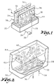
- FIG. 2 illustrates an alternative apparatus operable to implement the "self release” cycle for making “slush.”
- the "slush” is contained in a tank 50. Disposed along the bottom surface of the tank 50 is a heat exchanger member 52, which is cooled by refrigerant entering via conduit 54 and exiting via conduit 56. The temperature of the refrigerant is selected such that "slush", typically illustrated at reference numeral 35 forms on and adheres to the upper surface of the heat exchanger member 52 as the water based liquid contained in tank 50 is cooled.
- the accumulated "slush” interacts with a force due to buoyancy. As the mass of the accumulated “slush” increases, this force becomes sufficient to separate all or part of the accumulated "slush” 35 from the heat exchanger member 52.
- the separated “slush” floats upward, as typically illustrated at reference numerals 60 and 65 and mixes with the contents 44 of the tank 50.
- the contents of the tank 50 may be either"slush” or the water based liquid, depending on the prior operational history of the system.
- FIG. 3 illustrates second alternative apparatus operable to implement the "self release” cycle for making “slush.”
- the illustrated apparatus utilizes a two sided heat exchanger 70, positioned near the bottom of a tank 73.
- the tank 73 contains either the water based liquid or "slush,” depending on the prior operating history of the system.
- Refrigerant enters the heat exchanger member 70 through conduit 72 and exits by way of conduit 74.
- the temperature of the refrigerant is selected such that "slush" forms and accumulates on the outer surfaces of the heat exchange member 70, as typically illustrated at Reference Numeral 76 and 78.
- the characteristics of the water based liquid, the characteristics of the "slush” and the surfaces of the heat exchanger element 70 are selected such that the force of buoyancy is sufficient to separate at least a portion of the accumulated "slush” from the surfaces of the heat exchanger 70, causing the separated “slush”to float toward the surface.
- the separated “slush” mixes with the contents of the tank 73.
- Typical accumulations of "slush" which have separated from the heat exchanger 70 are illustrated at reference numeral 75.
- a primary use of the "slush" making system, which is the subject of this invention, is in air-conditioning and other cooling systems.
- Liquid is circulated from a storage tank 98 and caused to flow over the heat exchanger 90 by a distributor 100 and a pump 102.
- Primary coolant in the form of "slush” is circulated through the air conditioning system as the primary coolant in the form of "slush” or cold liquid by a pump 104 and returned to the tank 98 via a conduit 106.
- a plurality of heat exchangers may also be used.
- Other conventional refrigeration devices may be incorporated into the system to produce and control the flow of the refrigerant.
- FIG. 5 An embodiment of an air conditioning system utilizing the "no penalty" defrost cycle is illustrated in Figure 5. This embodiment is similar to the embodiment illustrated in Figure 4. To emphasize this similarity, the same reference numbers are used in these figures to identify similar components.
- FIG. 5 illustrates apparatus operable to implement the "no penalty" harvesting technique.
- Refrigerant is supplied to the heat exchangers, 90 and 90A, by a compressor 94 via a condenser 95, a high pressure receiver 97 and conduits, 92 and 92A. This is a typical prior art refrigeration cycle.
- This embodiment includes additional valves and conduits which permit refrigerant to be periodically directed through the heat exchangers to assure that all ice accumulations are periodically cleaned from these surfaces.
- two valves, 112 and 116 permit the refrigerant flow to be selectively directed from the outputs of heat exchangers, 90 and 90A.
- valve 112 permits the refrigerant from one of the heat exchangers to be directed to the input of the other heat exchanger 90.
- Additional conventional pressure regulating apparatus 91 is required.
- the refrigerant at the output side of the heat exchangers, 90 and 90A is sufficiently warm to increase the temperature of the heat exchanger through which it flows.
- Energy stored in the refrigerant at the output of the heat exchanger is recovered using this technique and used to ensure that all of the accumulated "slush," typically illustrated at reference numeral 35, is periodically harvested.
- Energy used in this harvesting technique is normally dissipated without any useful contribution to the "slush" making cycle.
- the "no penalty" defrost cycle does not require additional energy input to implement the defrost portion of the cycle. This is the "no penalty" harvesting cycle previously discussed.
- the function of the compressor 94, the condenser 95, and the other components associated therewith is to produce the desired flow of refrigerant to cool the heat exchangers to produce the desired quantity of "slush".
- Other conventional refrigeration cycles and components may be used or incorporated into the illustrated embodiments of the invention to produce the desired cooling of the heat exchangers, 90 and 90A.
Landscapes
- Engineering & Computer Science (AREA)
- Physics & Mathematics (AREA)
- Mechanical Engineering (AREA)
- Thermal Sciences (AREA)
- General Engineering & Computer Science (AREA)
- Other Air-Conditioning Systems (AREA)
- Heat-Exchange Devices With Radiators And Conduit Assemblies (AREA)
- Materials Applied To Surfaces To Minimize Adherence Of Mist Or Water (AREA)
- Non-Alcoholic Beverages (AREA)
Abstract
Description
- This invention relates to methods for producing slush.
- In typical ice harvesting systems, ice is formed on the exterior surface of a heat transfer surface and periodically removed by means of a defrost harvesting cycle, which melts a thin layer of ice adjacent to the heat transfer surface. Overall efficiency of the system is adversely effected by the defrost harvesting cycle, which may utilize up to about 20% of the energy input to the system. Alternatively, mechanical harvesting techniques, also requiring additional energy, may be used.
- DE-A-1 401 559 (US-A-3 074 252) describes an ice making apparatus which in operation produces slush by a method as defined hereinbefore at the beginning. The ice making apparatus has a pair of vertical freezing plates arranged to face one another and each having a flat, vertical outer face facing outwards from the pair, and a flat, vertical back face facing the other freezing plate. Two deflector plates are fixed to the respective upper edges of the freezing plates and extend upwards and inwards towards each other. Immediately above the deflector plates is a distributor pan for water. The bottom of the distributor pan has two rows of drain holes, each row being directly above a respective one of the deflector plates. Each freezing plate is a heat exchanger having a pipe of refrigerant between the outer face and the back face for cooling water that drops from the distributor pan onto the deflector plate and runs down the outer face. At the start of an ice making operation, as the freezing plates cool down, the water flowing over the outer faces starts to freeze. The freezing is not instantaneous but takes place gradually so that an ice-slush forms which does not adhere to the outer faces but instead flows down into a trough. The trough feeds an arrangement of tanks from which water is recirculated by a pump to the distributor pan. The slush is substantially prevented from reaching the pump by the arrangement of tanks and a baffle. The cycling of water is continued until a film of ice builds up to a suitable thickness on the outer faces of the freezing plates. The ice is then harvested by stopping the refrigerating system and the water circulating pump and then warming the freezing element with a water spray at ambient temperature from a distributor pipe arranged between the deflector plates. The formation of the slush is regarded as an interference with the proper operation of this known apparatus.
- According to one aspect of the present invention, there is provided a method for producing slush, comprising directing a water-based liquid comprising water and electrolyte and/or non-electrolyte along a downward path on a downwardly extending surface of a heat exchanger, cooling said surface by flowing a refrigerant through said heat exchanger, and so selecting the temperature of the refrigerant in said heat exchanger, the nature of said surface and the composition of said water-based liquid that slush consisting of a mixture of said liquid and ice crystals forms and accumulates on said surface, and that forces resulting from gravity and the interactions between the said surface and the slush are sufficient to overcome the adhesion force between at least a portion of the slush and the said surface and to cause at least a portion of the slush to separate from the said surface.
- According to another aspect of the invention there is provided a method of producing slush comprising substantially filling a container with a water-based liquid comprising water and electrolyte and/or nonelectrolyte, and passing refrigerant through a heat exchanger disposed in a bottom region of the container and having at least one heat exchange surface in contact with the said liquid, the composition of the water-based liquid, the temperature of the refrigerant and the nature of the said surface being such that slush consisting of a mixture of the said liquid and ice crystals forms and accumulates on the said surface, the mass of the slush increasing until buoyancy causes at least a portion of the slush to be released from the said surface and float upwards in the container.
- The methods provided by the current invention save substantially all of the energy utilized in the harvesting portion of prior art ice making processes. In practising the present invention, a mass ("slush") is formed as a mixture of solids and a water based liquid on the surface of a heat exchanger. The solids are formed by cooling the water based liquid, which consists of a mixture of water and electrolytes or non-electrolytes, positioned in a heat exchange relationship with the heat exchanger. As the solids form, portions of the water based liquid are trapped therein to form "slush" which accumulates on the heat exchanger. This "slush" is harvested (removed from the surface of the heat exchanger) and mixed with an additional quantity of the water based liquid or with previously harvested "slush."
- Each interval of time, beginning when a particular accumulation of "slush" begins and extending to the point in time at which at least a portion of the accumulated "slush" releases from the heat exchanger and mixes with a larger quantity of the liquid or with previously harvested "slush," is defined as a "cycle."
- The invention provides methods for making "slush" using a "self release" or a "no penalty" harvesting technique, as further described below. Each of these harvesting techniques saves substantially all of the energy dissipated by the harvesting portion of prior art ice making processes.
- The method according to the invention uses an apparatus operable to implement a "slush" making cycle using a "self release" harvesting technique. The apparatus includes a heat exchange surface in heat exchange relationship with a water based liquid. As the liquid is cooled a soft mass ("slush") consisting of a mixture of solids (ice crystals) and the liquid is formed on a downwardly extending surface of a heat exchanger. Electrolytes and/or non-electrolytes in the water based liquid cause the "slush" to accumulate as a soft (as compared to frozen substantially pure water) mixture of ice crystals and the water based liquid. This "slush" accumulates until it attains sufficient size that the force of gravity and interactions with the water based liquid are sufficient to cause at least a portion of the accumulated "slush" to release from the surface of the heat exchanger. As the "slush" releases, it mixes with a larger quantity of the water based liquid or with previously harvested "slush" and frequently breaks into smaller pieces.
- The surfaces of the heat exchanger are selected to further reduce the adhesion between the accumulated "slush" and the heat exchanger. Surfaces believed to be most advantageous for use as heat exchanger surfaces are those having simple geometrical shapes, i. e. those substantially free of rapid changes in contour, such as flat planes and those having smooth surface finishes. Additionally, coatings such as FEP Teflon are useful in reducing adhesion.
- Other embodiments of the invention utilize heat exchangers submerged in either the water based liquid or in "slush," depending on the previous operating history of the system. As the heat exchanger is cooled, "slush" forms and accumulates on the surface of the heat exchanger. As the size and weight of the accumulated "slush" increases, the accumulated "slush" interacts with either the water based liquid or "slush" due to the force of buoyancy causing at least a portion of the accumulated "slush" to release from the heat exchanger and mix with the water based liquid or previously harvested "slush." The "slush" is collected and stored for use in cooling systems.
- The "no penalty" defrost cycle operates similarly to the "self release" cycle, except that heat is recovered from the refrigeration cycle and used to aid in releasing (harvesting) the accumulated "slush" from the heat exchanger. Recovery of heat from the refrigeration cycle requires a plurality of heat exchangers, with refrigerant being diverted from the high pressure receiver to the output of one or more selected heat exchangers to aid in release of "slush" accumulated thereon.
- Experience has shown that the area of the heat exchanger covered by a particular accumulation of "slush" before release occurs varies widely. However, the system can be operated continuously using the "self release" cycle without requiring either added heat or mechanical means to remove the accumulated "slush" from the heat exchanger surfaces.
- The system and technique for making "slush" which is the subject of this patent application includes two basic embodiments. Each embodiment utilizes a liquid comprising a water-electrolyte and/or water non-electrolyte solution or mixture in heat exchange relationship with a heat exchanger to form "slush" consisting of a mixture of the liquid and solids. The "slush" is accumulated on the heat exchanger and is harvested and mixed with an additional quantity of the liquid or with quantities of "slush" previous harvested.
- As an aid in evaluating these techniques, an overall efficiency and cost comparisons were done by David E. Knebel of Knebel and Associates. From this study, based on a two hundred ton installed capacity, the following costs per ton were calculated.

- This same study also estimated that for a usage of 400,000 annual tons-hours as a base, the following savings per year in the total operating cost would result:

- From the above analysis it is obvious that the above described "slush" making cycles offer the potential for reducing installation cost and the electrical energy usage requirements, while the slush storage system aids in reducing peak utility loads and annual operating cost.
- Figure 1 is a drawing illustrating apparatus operable to implement the "self release" cycle for making "slush."
- Figure 2 is a drawing illustrating alternative apparatus operable to implement the "self release" cycle for making "slush."
- Figure 3 is a drawing illustrating a second alternative apparatus operable to implement the "self release" cycle for making "slush."
- Figure 4 is a drawing illustrating an air conditioning system utilizing "slush" as the coolant.
- Figure 5 is a drawing illustrating the "no penalty" defrost "slush" making cycle.
- Figure 1 is a drawing illustrating apparatus operable to implement the "self release" cycle for making "slush." This apparatus operates according to the preferred embodiment of the invention.
- In this embodiment, the "slush," is harvested and collected in a
tank 20. The contents of thetank 20 is either "slush" or the water based liquid, depending on the prior operating history of the system. Liquid is separated from the contents oftank 20, if necessary using any convenient technique, and directed through aconduit 24 by apump 26. The output of thepump 26 is in turn directed byconduit 28 to distributors, 30 and 32. The volume of thetank 20 is selected to provide the desired thermal storage capacity. In the preferred embodiment of the invention, the liquid is a mixture of water and electrolytes and/or non-electrolytes, as previously discussed. - Liquid from the
distributors input conduit 38 and exiting by conduit 40. - The temperature of the refrigerant is selected such that as the water based liquid flows down the surfaces of the heat exchanger members, 34 and 36, portions of the liquid solidify to form ice crystals which accumulate thereon as a "slush," typically illustrated at
reference numeral 35. This "slush" is soft (as compared to a solid formed from freezing substantially pure water) and consists of a mixture of the water based liquid and ice crystals. Low adhesion forces (as compared to substantially crystalline ice) are produced between the accumulated "slush" and the smooth vertical surfaces of the heat exchangers, 34 and 36. Low cohesion forces cause the "slush" to be soft, as described above. - For purposes of this patent application, the term "adhere" is used as a generic term for all forces tending to cause a mass consisting of a mixture of solids and a liquid to be attracted to a surface.
- Also, for purposes of this patent application, the term "cohere" is used as a generic term for all forces tending to cause ice crystals and a liquid to be attracted to each other.
- The accumulated "slush" interacts with the water based liquid and the forces of gravity. The magnitude of these interactions increases as the accumulated "slush" 35 increases in size and/or thickness. As these interactions become sufficient to overcome the adhesion and/or cohesion forces, portions or all of the accumulated "slush" releases from the heat exchanger members, 34 and 36, and mixes with the
contents 44 of thetank 20. The contents of thetank 20 may be "slush" or the water based liquid, depending on the operating 16 history of the system. - In order to assure operation of the system and "slush" making cycle as described above, it is helpful to select the surfaces for the heat exchanger members, 34 and 36, and the water based liquid such that the adhesion and/or cohesion forces are reduced to the lowest practical level. That is to say, it is currently believed that as the adhesion and/or cohesion forces are decreased, the operation of the cycle improves. A complete absence of adhesion and cohesion forces is desirable. However, this goal has not been attained and may not be attainable using current technology.
- However, significant reductions in adhesion and cohesion are accomplished in accordance with the present invention by utilizing a water based liquid that includes electrolytes and/or non-electrolytes, as well as heat exchanger members, 34 and 36, having surfaces which reduce adhesion forces. Liquids comprising a mixture of electrolytes and/or non-electrolytes, such as a 30/70 calcium acetate-magnesium acetate mixture or ethylene glycol, respectively, and water are suitable for use in all embodiments of. the invention. Such liquids have previously been referred to as "water based." Similarly the surfaces of the heat exchange members, 34 and 36, may be coated with material such as Teflon or its derivatives to reduce adhesion forces.
- Figure 2 illustrates an alternative apparatus operable to implement the "self release" cycle for making "slush." The "slush" is contained in a
tank 50. Disposed along the bottom surface of thetank 50 is aheat exchanger member 52, which is cooled by refrigerant entering viaconduit 54 and exiting viaconduit 56. The temperature of the refrigerant is selected such that "slush", typically illustrated atreference numeral 35 forms on and adheres to the upper surface of theheat exchanger member 52 as the water based liquid contained intank 50 is cooled. The accumulated "slush" interacts with a force due to buoyancy. As the mass of the accumulated "slush" increases, this force becomes sufficient to separate all or part of the accumulated "slush" 35 from theheat exchanger member 52. The separated "slush" floats upward, as typically illustrated atreference numerals contents 44 of thetank 50. As with previous embodiments, the contents of thetank 50 may be either"slush" or the water based liquid, depending on the prior operational history of the system. - As with the embodiment illustrated in Figure 1, it is necessary to select the water based liquid as well as the characteristics of the
heat exchanger member 52 such that the force of buoyancy interacts with the accumulated "slush", and become sufficient to detach a portion or all of the accumulated "slush" from theheat exchanger 52. This result can be achieved by using suitable electrolytes and/or non-electrolytes in the water based liquid. Heat exchangers having low cohesion surfaces further aid in releasing the accumulated "slush". The electrolytes and heat exchanger surfaces described above are also usable in this apparatus. - Figure 3 illustrates second alternative apparatus operable to implement the "self release" cycle for making "slush." The illustrated apparatus utilizes a two
sided heat exchanger 70, positioned near the bottom of atank 73. Thetank 73 contains either the water based liquid or "slush," depending on the prior operating history of the system. - Refrigerant enters the
heat exchanger member 70 throughconduit 72 and exits by way ofconduit 74. The temperature of the refrigerant is selected such that "slush" forms and accumulates on the outer surfaces of theheat exchange member 70, as typically illustrated atReference Numeral - As with the previous embodiments, the characteristics of the water based liquid, the characteristics of the "slush" and the surfaces of the
heat exchanger element 70 are selected such that the force of buoyancy is sufficient to separate at least a portion of the accumulated "slush" from the surfaces of theheat exchanger 70, causing the separated "slush"to float toward the surface. The separated "slush" mixes with the contents of thetank 73. Typical accumulations of "slush" which have separated from theheat exchanger 70 are illustrated atreference numeral 75. - A primary use of the "slush" making system, which is the subject of this invention, is in air-conditioning and other cooling systems.
- Use of the improved "slush" making cycle as applied to a typical air conditioning system is illustrated in Figure 4. In this embodiment cold refrigerant is supplied to
heat exchanger 90 by acompressor 94 via acondenser 95,high pressure receiver 97 and aconduit 92. Refrigerant is returned to thecompressor 94 by aconduit 96. This is a typical prior art refrigeration cycle. - Liquid is circulated from a
storage tank 98 and caused to flow over theheat exchanger 90 by adistributor 100 and apump 102. Primary coolant in the form of "slush" is circulated through the air conditioning system as the primary coolant in the form of "slush" or cold liquid by apump 104 and returned to thetank 98 via aconduit 106. A plurality of heat exchangers may also be used. Other conventional refrigeration devices may be incorporated into the system to produce and control the flow of the refrigerant. - An embodiment of an air conditioning system utilizing the "no penalty" defrost cycle is illustrated in Figure 5. This embodiment is similar to the embodiment illustrated in Figure 4. To emphasize this similarity, the same reference numbers are used in these figures to identify similar components.
- Figure 5 illustrates apparatus operable to implement the "no penalty" harvesting technique. Refrigerant is supplied to the heat exchangers, 90 and 90A, by a
compressor 94 via acondenser 95, ahigh pressure receiver 97 and conduits, 92 and 92A. This is a typical prior art refrigeration cycle. - This embodiment includes additional valves and conduits which permit refrigerant to be periodically directed through the heat exchangers to assure that all ice accumulations are periodically cleaned from these surfaces. For example, two valves, 112 and 116, permit the refrigerant flow to be selectively directed from the outputs of heat exchangers, 90 and 90A. For example,
valve 112 permits the refrigerant from one of the heat exchangers to be directed to the input of theother heat exchanger 90. Additional conventionalpressure regulating apparatus 91 is required. - The refrigerant at the output side of the heat exchangers, 90 and 90A, is sufficiently warm to increase the temperature of the heat exchanger through which it flows. Energy stored in the refrigerant at the output of the heat exchanger is recovered using this technique and used to ensure that all of the accumulated "slush," typically illustrated at
reference numeral 35, is periodically harvested. Energy used in this harvesting technique is normally dissipated without any useful contribution to the "slush" making cycle. Thus, the "no penalty" defrost cycle does not require additional energy input to implement the defrost portion of the cycle. This is the "no penalty" harvesting cycle previously discussed. - The function of the
compressor 94, thecondenser 95, and the other components associated therewith is to produce the desired flow of refrigerant to cool the heat exchangers to produce the desired quantity of "slush". Other conventional refrigeration cycles and components may be used or incorporated into the illustrated embodiments of the invention to produce the desired cooling of the heat exchangers, 90 and 90A.
Claims (6)
- A method for producing slush, comprising directing a water-based liquid comprising water and electrolyte and/or non-electrolyte along a downward path on a downwardly extending surface of a heat exchanger (34,36), cooling said surface by flowing a refrigerant through said heat exchanger (34,36), and so selecting the temperature of the refrigerant in the heat exchanger (34,36), the nature of said surface and the composition of said water-based liquid that slush consisting of a mixture of said liquid and ice crystals forms and accumulates on said surface, and that forces resulting from gravity and the interactions between the said surface and the slush are sufficient to overcome the adhesion force between at least a portion of the slush and the said surface and to cause at least a portion of the slush to separate from the said surface.
- A method according to claim 1, characterised in that a coating is provided affixed to the said surface, the material of the coating being selected to reduce nucleation of the said liquid and to minimise adhesion between the coating and the slush.
- A method according to claim 1 or 2, characterised in that the said liquid comprises water and an electrolyte and the electrolyte comprises three parts calcium acetate and seven parts magnesium acetate.
- A method according to claim 1 or 2 or 3, characterised in that the slush accumulates on the said surface as a sheet of indefinite area and having an average thickness of less than one half inch (1.27cm).
- A method of producing slush comprising substantially filling a container (50) with a water based liquid comprising water and electrolyte and/or nonelectrolyte, and passing refrigerant through a heat exchanger (52) disposed in a bottom region of the container and having at least one heat exchange surface in contact with the said liquid, the composition of the water-based liquid, the temperature of the refrigerant and the nature of the said surface being such that slush consisting of a mixture of the said liquid and ice crystals forms and accumulates on the said surface, the mass of the slush increasing until buoyancy causes at least a portion of the slush to be released from the said surface and float upwards in the container (50).
- A method according to claim 5, characterised in that the said surface is provided by a layer of material affixed to the heat exchanger (52), the material being such as to reduce adhesion forces between the slush and the heat exchanger (52).
Applications Claiming Priority (4)
| Application Number | Priority Date | Filing Date | Title |
|---|---|---|---|
| US07/276,137 US4907415A (en) | 1988-11-23 | 1988-11-23 | Slush ice making system and methods |
| US276137 | 1988-11-23 | ||
| CA002001335A CA2001335C (en) | 1988-11-23 | 1989-10-24 | Slush ice making system and methods |
| PCT/US1989/004909 WO1990005882A1 (en) | 1988-11-23 | 1989-11-01 | Slush ice making system and methods |
Publications (3)
| Publication Number | Publication Date |
|---|---|
| EP0445211A1 EP0445211A1 (en) | 1991-09-11 |
| EP0445211A4 EP0445211A4 (en) | 1992-05-20 |
| EP0445211B1 true EP0445211B1 (en) | 1995-03-08 |
Family
ID=25673775
Family Applications (1)
| Application Number | Title | Priority Date | Filing Date |
|---|---|---|---|
| EP90900502A Expired - Lifetime EP0445211B1 (en) | 1988-11-23 | 1989-11-01 | Methods for producing slush |
Country Status (7)
| Country | Link |
|---|---|
| US (1) | US4907415A (en) |
| EP (1) | EP0445211B1 (en) |
| AT (1) | ATE119659T1 (en) |
| AU (1) | AU630644B2 (en) |
| CA (1) | CA2001335C (en) |
| DE (1) | DE68921639T2 (en) |
| WO (1) | WO1990005882A1 (en) |
Families Citing this family (52)
| Publication number | Priority date | Publication date | Assignee | Title |
|---|---|---|---|---|
| DE9102051U1 (en) * | 1991-02-21 | 1992-06-25 | Klüe, Ulrich, Dipl.-Ing., 2054 Geesthacht | Ice making device |
| US5953924A (en) * | 1991-06-17 | 1999-09-21 | Y. T. Li Engineering, Inc. | Apparatus, process and system for tube and whip rod heat exchanger |
| US5768894A (en) * | 1991-06-17 | 1998-06-23 | Y.T. Li Engineering, Inc. | Apparatus, process and system for tube and whip rod heat exchanger |
| US5363660A (en) * | 1991-06-17 | 1994-11-15 | Y. T. Li Engineering, Inc. | Orbital type freezing apparatus and method |
| US5419151A (en) * | 1992-05-29 | 1995-05-30 | Hoshizaki Denki Kabushiki Kaisha | Ice making machine |
| US5402650A (en) * | 1994-05-03 | 1995-04-04 | The Curators Of The University Of Missouri | Thermal storage composition for low energy ice harvesting, method of using same |
| US5582018A (en) * | 1995-08-30 | 1996-12-10 | Scotsman Group, Inc. | Method for preventing formation of ice slush in an ice maker |
| NL1002528C2 (en) * | 1996-03-05 | 1997-02-07 | Omega Engineering B V | Apparatus for making ice. |
| US5632159A (en) * | 1996-03-29 | 1997-05-27 | North Star Ice Equipment Corporation | Cooling disk for flake ice machine |
| US5924301A (en) * | 1997-09-09 | 1999-07-20 | Cook; Richard E. | Apparatus for ice harvesting in commercial ice machines |
| US5971061A (en) * | 1998-09-21 | 1999-10-26 | Y.T. Li Engineering, Inc. | Edge-hanging orbital rod support and drive for vertical tube-type heat exchanger |
| US6381968B1 (en) * | 2000-03-21 | 2002-05-07 | O'donoghue, Jr. Joseph | Apparatus and method for forming ice and frosted sculptures |
| US8721583B2 (en) * | 2008-10-31 | 2014-05-13 | The Invention Science Fund I, Llc | Compositions and methods for surface abrasion with frozen particles |
| US9072688B2 (en) | 2008-10-31 | 2015-07-07 | The Invention Science Fund I, Llc | Compositions and methods for therapeutic delivery with frozen particles |
| US9060931B2 (en) * | 2008-10-31 | 2015-06-23 | The Invention Science Fund I, Llc | Compositions and methods for delivery of frozen particle adhesives |
| US8221480B2 (en) | 2008-10-31 | 2012-07-17 | The Invention Science Fund I, Llc | Compositions and methods for biological remodeling with frozen particle compositions |
| US8788211B2 (en) * | 2008-10-31 | 2014-07-22 | The Invention Science Fund I, Llc | Method and system for comparing tissue ablation or abrasion data to data related to administration of a frozen particle composition |
| US8603495B2 (en) * | 2008-10-31 | 2013-12-10 | The Invention Science Fund I, Llc | Compositions and methods for biological remodeling with frozen particle compositions |
| US20100111836A1 (en) * | 2008-10-31 | 2010-05-06 | Searete Llc, A Limited Liability Corporation Of The State Of Delaware | Compositions and methods for therapeutic delivery with frozen particles |
| US8414356B2 (en) * | 2008-10-31 | 2013-04-09 | The Invention Science Fund I, Llc | Systems, devices, and methods for making or administering frozen particles |
| US20100111845A1 (en) * | 2008-10-31 | 2010-05-06 | Searete Llc, A Limited Liability Corporation Of The State Of Delaware | Compositions and methods for therapeutic delivery with frozen particles |
| US9050317B2 (en) * | 2008-10-31 | 2015-06-09 | The Invention Science Fund I, Llc | Compositions and methods for therapeutic delivery with frozen particles |
| US9060926B2 (en) * | 2008-10-31 | 2015-06-23 | The Invention Science Fund I, Llc | Compositions and methods for therapeutic delivery with frozen particles |
| US8725420B2 (en) * | 2008-10-31 | 2014-05-13 | The Invention Science Fund I, Llc | Compositions and methods for surface abrasion with frozen particles |
| US9060934B2 (en) * | 2008-10-31 | 2015-06-23 | The Invention Science Fund I, Llc | Compositions and methods for surface abrasion with frozen particles |
| US8731841B2 (en) * | 2008-10-31 | 2014-05-20 | The Invention Science Fund I, Llc | Compositions and methods for therapeutic delivery with frozen particles |
| US9050070B2 (en) * | 2008-10-31 | 2015-06-09 | The Invention Science Fund I, Llc | Compositions and methods for surface abrasion with frozen particles |
| US8551505B2 (en) * | 2008-10-31 | 2013-10-08 | The Invention Science Fund I, Llc | Compositions and methods for therapeutic delivery with frozen particles |
| US9056047B2 (en) | 2008-10-31 | 2015-06-16 | The Invention Science Fund I, Llc | Compositions and methods for delivery of frozen particle adhesives |
| US8762067B2 (en) | 2008-10-31 | 2014-06-24 | The Invention Science Fund I, Llc | Methods and systems for ablation or abrasion with frozen particles and comparing tissue surface ablation or abrasion data to clinical outcome data |
| US20100111857A1 (en) | 2008-10-31 | 2010-05-06 | Boyden Edward S | Compositions and methods for surface abrasion with frozen particles |
| US8563012B2 (en) | 2008-10-31 | 2013-10-22 | The Invention Science Fund I, Llc | Compositions and methods for administering compartmentalized frozen particles |
| US8409376B2 (en) | 2008-10-31 | 2013-04-02 | The Invention Science Fund I, Llc | Compositions and methods for surface abrasion with frozen particles |
| US20100111831A1 (en) * | 2008-10-31 | 2010-05-06 | Searete Llc, A Limited Liability Corporation Of The State Of Delaware | Compositions and methods for surface abrasion with frozen particles |
| US20100111835A1 (en) * | 2008-10-31 | 2010-05-06 | Searete Llc, A Limited Liability Corporation Of The State Of Delaware | Compositions and methods for therapeutic delivery with frozen particles |
| US8568363B2 (en) * | 2008-10-31 | 2013-10-29 | The Invention Science Fund I, Llc | Frozen compositions and methods for piercing a substrate |
| US8545855B2 (en) * | 2008-10-31 | 2013-10-01 | The Invention Science Fund I, Llc | Compositions and methods for surface abrasion with frozen particles |
| US8603494B2 (en) * | 2008-10-31 | 2013-12-10 | The Invention Science Fund I, Llc | Compositions and methods for administering compartmentalized frozen particles |
| US8731840B2 (en) * | 2008-10-31 | 2014-05-20 | The Invention Science Fund I, Llc | Compositions and methods for therapeutic delivery with frozen particles |
| US9072799B2 (en) * | 2008-10-31 | 2015-07-07 | The Invention Science Fund I, Llc | Compositions and methods for surface abrasion with frozen particles |
| US8793075B2 (en) * | 2008-10-31 | 2014-07-29 | The Invention Science Fund I, Llc | Compositions and methods for therapeutic delivery with frozen particles |
| US20100178038A1 (en) * | 2009-01-12 | 2010-07-15 | Mediatek Inc. | Video player |
| US9310140B2 (en) | 2012-02-07 | 2016-04-12 | Rebound Technologies, Inc. | Methods, systems, and devices for thermal enhancement |
| RU2490567C1 (en) * | 2012-09-10 | 2013-08-20 | Сергей Викторович Коровкин | Method of ice generation |
| DE102013208094B4 (en) * | 2013-05-03 | 2017-08-31 | Hochschule Karlsruhe-Technik Und Wirtschaft | Process and apparatus for making ice-cream |
| US10995993B2 (en) | 2014-09-27 | 2021-05-04 | Rebound Technologies, Inc. | Thermal recuperation methods, systems, and devices |
| DE102015104909B3 (en) * | 2015-03-30 | 2016-09-29 | MBS Naturstromspeicher GmbH | Energy storage, power plant with energy storage and method of operation thereof |
| US10584904B2 (en) | 2017-03-27 | 2020-03-10 | Rebound Technologies, Inc. | Cycle enhancement methods, systems, and devices |
| US10544974B2 (en) | 2017-09-01 | 2020-01-28 | Rebound Technologies, Inc. | Solid production methods, systems, and devices |
| WO2019165328A1 (en) | 2018-02-23 | 2019-08-29 | Rebound Technologies, Inc. | Freeze point suppression cycle control systems, methods, and devices |
| WO2020132467A1 (en) | 2018-12-20 | 2020-06-25 | Rebound Technologies, Inc. | Thermo-chemical recuperation systems, devices, and methods |
| US11441830B2 (en) | 2018-12-26 | 2022-09-13 | Rebound Technologies, Inc. | Solid production systems, devices, and methods utilizing oleophilic surfaces |
Family Cites Families (17)
| Publication number | Priority date | Publication date | Assignee | Title |
|---|---|---|---|---|
| US2161953A (en) * | 1937-03-12 | 1939-06-13 | Edison Splitdorf Corp | Rotor for magneto electric generator |
| US2656689A (en) * | 1948-06-15 | 1953-10-27 | Muffly Glenn | Method of and apparatus for automatic ice-making |
| US2833126A (en) * | 1950-11-14 | 1958-05-06 | Muffly Glenn | Ice making method |
| NL285073A (en) * | 1959-07-10 | |||
| US3314473A (en) * | 1965-07-16 | 1967-04-18 | Gen Dynamics Corp | Crystal growth control in heat exchangers |
| US3423952A (en) * | 1967-03-10 | 1969-01-28 | Lloyd R Pugh | Ice making apparatus |
| DE1776153A1 (en) * | 1968-09-28 | 1971-07-08 | Johnson Dilys | Method and device for making ice cubes |
| US4501775A (en) * | 1973-07-19 | 1985-02-26 | The Dow Chemical Company | Method for reducing the strength of ice |
| US4044568A (en) * | 1975-12-22 | 1977-08-30 | Turbo Refrigerating Company | Space heating and cooling system |
| US4185467A (en) * | 1977-11-18 | 1980-01-29 | Frick Comany | Icemaker liquid refrigerant defrost system |
| US4249388A (en) * | 1980-01-30 | 1981-02-10 | Demco, Inc. | Automatic liquid ice system |
| US4446910A (en) * | 1980-05-22 | 1984-05-08 | General Electric Company | Two-phase thermal storage means and method |
| US4300355A (en) * | 1980-07-03 | 1981-11-17 | Air Products And Chemicals, Inc. | In-line lin slush making for concrete cooling |
| DE3124379A1 (en) * | 1981-06-22 | 1983-02-03 | Oleg 5000 Köln Stolz | Heat exchanger with a small overall volume and weight |
| CA1208027A (en) * | 1984-06-19 | 1986-07-22 | Vladimir Goldstein | Ice making machine and method |
| DE3484537D1 (en) * | 1984-07-17 | 1991-06-06 | Sunwell Eng Co Ltd | ICE PRODUCTION MACHINE. |
| US4625525A (en) * | 1985-06-03 | 1986-12-02 | Speciality Equipment Companies, Inc. Taylor Freezer Division | Apparatus and method for producing frosted drinks |
-
1988
- 1988-11-23 US US07/276,137 patent/US4907415A/en not_active Expired - Fee Related
-
1989
- 1989-10-24 CA CA002001335A patent/CA2001335C/en not_active Expired - Fee Related
- 1989-11-01 DE DE68921639T patent/DE68921639T2/en not_active Expired - Fee Related
- 1989-11-01 AU AU46522/89A patent/AU630644B2/en not_active Ceased
- 1989-11-01 AT AT90900502T patent/ATE119659T1/en not_active IP Right Cessation
- 1989-11-01 EP EP90900502A patent/EP0445211B1/en not_active Expired - Lifetime
- 1989-11-01 WO PCT/US1989/004909 patent/WO1990005882A1/en not_active Ceased
Also Published As
| Publication number | Publication date |
|---|---|
| AU630644B2 (en) | 1992-11-05 |
| CA2001335C (en) | 1997-01-28 |
| EP0445211A4 (en) | 1992-05-20 |
| DE68921639T2 (en) | 1995-10-12 |
| ATE119659T1 (en) | 1995-03-15 |
| AU4652289A (en) | 1990-06-12 |
| DE68921639D1 (en) | 1995-04-13 |
| EP0445211A1 (en) | 1991-09-11 |
| CA2001335A1 (en) | 1991-04-24 |
| US4907415A (en) | 1990-03-13 |
| WO1990005882A1 (en) | 1990-05-31 |
Similar Documents
| Publication | Publication Date | Title |
|---|---|---|
| US4907415A (en) | Slush ice making system and methods | |
| US4302944A (en) | Thermal storage method and apparatus | |
| US4408654A (en) | Accumulator for storing heat or cold | |
| US4254635A (en) | Installation for the storage of continuously generated coldness and for the intermittent emission of at least a portion of the stored cold | |
| EP0643819B1 (en) | Cold storage apparatus | |
| US4832068A (en) | Liquid/gas bypass | |
| US3074252A (en) | Ice making apparatus | |
| WO1985002458A1 (en) | Method and equipment for utilization of the freezing heat of water as a source of heat of a heat pump | |
| CN217423675U (en) | Heat exchanger and refrigerating plant with delay defrosting effect | |
| KR100378531B1 (en) | coolant and oil separating/ collecting device of turbo chiller | |
| US5231852A (en) | Melt system for liquid purification by batch crystallization | |
| CN221279709U (en) | Composite evaporative condenser | |
| JPH0827039B2 (en) | Ice heat storage device | |
| JP2509508Y2 (en) | Heat storage equipment for air conditioning | |
| RU2067269C1 (en) | Method of defrosting refrigerating chamber batteries | |
| JPH07293945A (en) | Heat storage tank for dynamic ice thermal storage system | |
| JP2853439B2 (en) | Absorption type ice machine | |
| JPS58117937A (en) | Coldness heat accumulator | |
| JPH09170771A (en) | Indoor unit for ice storage system | |
| SU595601A1 (en) | Continuous ice-generator | |
| JPH08285418A (en) | Discharge method of supercooled water in supercooled ice making system | |
| JPS58117938A (en) | Ice heat-accumulating method for air-conditioning heat-accumulating tank | |
| JP2000337668A (en) | Ice storage method and device | |
| JPH08338674A (en) | Ice heat storage device and method of operating the same | |
| JP2000097528A (en) | Ice storage system |
Legal Events
| Date | Code | Title | Description |
|---|---|---|---|
| PUAI | Public reference made under article 153(3) epc to a published international application that has entered the european phase |
Free format text: ORIGINAL CODE: 0009012 |
|
| 17P | Request for examination filed |
Effective date: 19910516 |
|
| AK | Designated contracting states |
Kind code of ref document: A1 Designated state(s): AT BE CH DE FR GB IT LI LU NL SE |
|
| A4 | Supplementary search report drawn up and despatched |
Effective date: 19920402 |
|
| AK | Designated contracting states |
Kind code of ref document: A4 Designated state(s): AT BE CH DE FR GB IT LI LU NL SE |
|
| 17Q | First examination report despatched |
Effective date: 19921215 |
|
| GRAA | (expected) grant |
Free format text: ORIGINAL CODE: 0009210 |
|
| RAP3 | Party data changed (applicant data changed or rights of an application transferred) |
Owner name: CURATOR OF THE UNIVERSITY OF MISSOURI |
|
| AK | Designated contracting states |
Kind code of ref document: B1 Designated state(s): AT BE CH DE FR GB IT LI LU NL SE |
|
| REF | Corresponds to: |
Ref document number: 119659 Country of ref document: AT Date of ref document: 19950315 Kind code of ref document: T |
|
| ITF | It: translation for a ep patent filed | ||
| REF | Corresponds to: |
Ref document number: 68921639 Country of ref document: DE Date of ref document: 19950413 |
|
| ET | Fr: translation filed | ||
| PLBE | No opposition filed within time limit |
Free format text: ORIGINAL CODE: 0009261 |
|
| STAA | Information on the status of an ep patent application or granted ep patent |
Free format text: STATUS: NO OPPOSITION FILED WITHIN TIME LIMIT |
|
| 26N | No opposition filed | ||
| PGFP | Annual fee paid to national office [announced via postgrant information from national office to epo] |
Ref country code: SE Payment date: 19961115 Year of fee payment: 8 Ref country code: FR Payment date: 19961115 Year of fee payment: 8 |
|
| PGFP | Annual fee paid to national office [announced via postgrant information from national office to epo] |
Ref country code: AT Payment date: 19961119 Year of fee payment: 8 |
|
| PGFP | Annual fee paid to national office [announced via postgrant information from national office to epo] |
Ref country code: NL Payment date: 19961120 Year of fee payment: 8 |
|
| PGFP | Annual fee paid to national office [announced via postgrant information from national office to epo] |
Ref country code: DE Payment date: 19961122 Year of fee payment: 8 Ref country code: CH Payment date: 19961122 Year of fee payment: 8 |
|
| PGFP | Annual fee paid to national office [announced via postgrant information from national office to epo] |
Ref country code: BE Payment date: 19961126 Year of fee payment: 8 |
|
| PGFP | Annual fee paid to national office [announced via postgrant information from national office to epo] |
Ref country code: GB Payment date: 19961128 Year of fee payment: 8 |
|
| PGFP | Annual fee paid to national office [announced via postgrant information from national office to epo] |
Ref country code: LU Payment date: 19961130 Year of fee payment: 8 |
|
| PG25 | Lapsed in a contracting state [announced via postgrant information from national office to epo] |
Ref country code: LU Free format text: LAPSE BECAUSE OF NON-PAYMENT OF DUE FEES Effective date: 19971101 Ref country code: GB Free format text: LAPSE BECAUSE OF NON-PAYMENT OF DUE FEES Effective date: 19971101 Ref country code: AT Free format text: LAPSE BECAUSE OF NON-PAYMENT OF DUE FEES Effective date: 19971101 |
|
| PG25 | Lapsed in a contracting state [announced via postgrant information from national office to epo] |
Ref country code: SE Free format text: LAPSE BECAUSE OF NON-PAYMENT OF DUE FEES Effective date: 19971102 |
|
| PG25 | Lapsed in a contracting state [announced via postgrant information from national office to epo] |
Ref country code: LI Free format text: LAPSE BECAUSE OF NON-PAYMENT OF DUE FEES Effective date: 19971130 Ref country code: FR Free format text: THE PATENT HAS BEEN ANNULLED BY A DECISION OF A NATIONAL AUTHORITY Effective date: 19971130 Ref country code: CH Free format text: LAPSE BECAUSE OF NON-PAYMENT OF DUE FEES Effective date: 19971130 Ref country code: BE Free format text: LAPSE BECAUSE OF NON-PAYMENT OF DUE FEES Effective date: 19971130 |
|
| BERE | Be: lapsed |
Owner name: CURATOR OF THE UNIVERSITY OF MISSOURI Effective date: 19971130 |
|
| PG25 | Lapsed in a contracting state [announced via postgrant information from national office to epo] |
Ref country code: NL Free format text: LAPSE BECAUSE OF NON-PAYMENT OF DUE FEES Effective date: 19980601 |
|
| GBPC | Gb: european patent ceased through non-payment of renewal fee |
Effective date: 19971101 |
|
| REG | Reference to a national code |
Ref country code: CH Ref legal event code: PL |
|
| PG25 | Lapsed in a contracting state [announced via postgrant information from national office to epo] |
Ref country code: DE Free format text: LAPSE BECAUSE OF NON-PAYMENT OF DUE FEES Effective date: 19980801 |
|
| EUG | Se: european patent has lapsed |
Ref document number: 90900502.7 |
|
| NLV4 | Nl: lapsed or anulled due to non-payment of the annual fee |
Effective date: 19980601 |
|
| REG | Reference to a national code |
Ref country code: FR Ref legal event code: ST |
|
| PG25 | Lapsed in a contracting state [announced via postgrant information from national office to epo] |
Ref country code: IT Free format text: LAPSE BECAUSE OF NON-PAYMENT OF DUE FEES;WARNING: LAPSES OF ITALIAN PATENTS WITH EFFECTIVE DATE BEFORE 2007 MAY HAVE OCCURRED AT ANY TIME BEFORE 2007. THE CORRECT EFFECTIVE DATE MAY BE DIFFERENT FROM THE ONE RECORDED. Effective date: 20051101 |