EP0445057A2 - Entzerrer mit Anpassung an mehrere Datenraten - Google Patents
Entzerrer mit Anpassung an mehrere Datenraten Download PDFInfo
- Publication number
- EP0445057A2 EP0445057A2 EP91480013A EP91480013A EP0445057A2 EP 0445057 A2 EP0445057 A2 EP 0445057A2 EP 91480013 A EP91480013 A EP 91480013A EP 91480013 A EP91480013 A EP 91480013A EP 0445057 A2 EP0445057 A2 EP 0445057A2
- Authority
- EP
- European Patent Office
- Prior art keywords
- equalizer
- state
- data rate
- equalizers
- transmission media
- Prior art date
- Legal status (The legal status is an assumption and is not a legal conclusion. Google has not performed a legal analysis and makes no representation as to the accuracy of the status listed.)
- Ceased
Links
Images


Classifications
-
- H—ELECTRICITY
- H04—ELECTRIC COMMUNICATION TECHNIQUE
- H04L—TRANSMISSION OF DIGITAL INFORMATION, e.g. TELEGRAPHIC COMMUNICATION
- H04L25/00—Baseband systems
- H04L25/02—Details ; arrangements for supplying electrical power along data transmission lines
- H04L25/03—Shaping networks in transmitter or receiver, e.g. adaptive shaping networks
- H04L25/03878—Line equalisers; line build-out devices
Definitions
- This invention relates to equalizers for use with data signal transmission and, more particularly to a multi-data rate selectable equalizer which will equalize a transmission media over which one of a plurality of data signals having different data rates are selectively transmitted.
- the IEEE 802.5 Token Ring Local Area Network uses a balanced twisted pair wire for data transmission.
- data is transmitted using an encoding technique known as differential Manchester encoding.
- differential Manchester encoding As the signal travels down the twisted pair, it undergoes phase and amplitude distortion which varies with the length of the transmission line and the data rate. This distortion gives rise to intersymbol interference and may be corrected by using an equalizer circuit located at the receiving end.
- Most of the prior equalizers are not used for equalizing signals at different data rates. Solutions to the equalization of multi-data rate transmission systems have been given. But all these solutions have disadvantages which are not desirable such as signal distorsion and excessive feed through of unwanted signals.
- the object of the present invention is an equalizer circuit which can selectively equalize signals at one or more than one data rate.
- the equalizer circuit includes a plurality of equalizers each adapted for connection to the transmission medium and arranged to equalize the transmission medium for signals at a different one of the more than one different data rates.
- Each of the equalizers includes a controllable means having a first state in which the equalizer is operative and a second state in which the equalizer is inoperative. Means are provided for selectively controlling a single means associated with one of the equalizers to a first state and the remaining means to the second state whereby the transmission media is equalized only by the equalizer associated with the means controlled to the first state and all of the other equalizers remain in the inoperative state.
- Figure 1 is a circuit diagram of a prior art equalizer suitable for equalizing a transmission media operating at a single data rate.
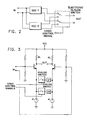
- FIGs 2 and 3 are circuit diagrams of early attempts which proved to be unsatisfactory at the data rates used in the contemplated application.
- Figure 4 shows a circuit diagram of a multiple equalizer constructed according to the invention.
- Figure 1 illustrates a prior art equalization circuit suitable where a single data rate is employed.
- the equalizer has a pair of input terminals 11 and a pair of output terminals 12.
- a differential amplifier/filter including a pair of transistors 14 and 15 provides an output at the pair of terminals 12 which is a function of the differential input applied at the pair of input terminals 11.
- a pair of constant current sources 16 and 17 regulate the total current through transistors 14 and 15.
- Figure 1 shows early attempts at solving the problem by providing two equalization circuits.
- the signal from the input is applied to a first equalizer 1 and a second equalizer 2 and an electronic analog switch is used to select one or the other equalizer.
- two impedances Z1 and Z2 are selected depending upon the data rate of the signal applied to the transmission media.
- Z1 is selected, for example, to compensate the transmission media for a 4 megabit data rate while Z2 will be selected to compensate the transmission media for a signal at a 16 megabit rate.
- a second disadvantage is the possibility of feedthrough of unwanted signals from the deselected equalizer.
- the extent of the feedthrough would depend entirely on the type of switch used. If a relay is used, the open contacts must have very little capacitance across them. Capacitance as small as 1 pico-farad could allow excessive feedthrough of unwanted signals. This low value of capacitance is not difficult to achieve with relay contacts.
- relay contacts have other disadvantages such as requiring power for operating the coil and requiring a large amount of area on circuit boards, etc.
- Analog switches used as an alternative have unique problems of their own. While they solve the space problem, they have electrical characteristics which are undesirable.
- Equalizer 40 includes a pair of transistors Q1 and Q2 having their collectors connected to Vcc by resistors R5 and R6 respectively.
- the emitters of Q1 and Q2 are connected to ground through controlled constant current sources Q3 and Q4.
- the bases of Q1 and Q2 are connected to the input terminals (Vin) and the collectors are connected to the output terminals (V out).
- a pair of resistors R1 and R2 provide bias voltage to the base of Q1 while resistors R3 and R4 provide bias voltage to the base of Q2.
- An impedance Z1, selected to equalize the transmission media at a given data rate, is connected between the emitters of Q1 and Q2.
- transistors Q3 and Q4 are permanently biased on which is not the case for the equalizer illustrated in Figure 4.
- a transistor Q5 has its collector connected to its base and to Vcc via R7. Current flows from Vcc through R7 and the base emitter of Q5.
- Q3 and Q4 are connected to Q5 and together form mirrored current sources for Q1 and Q2.
- B1 control voltage
- the transistors Q1 and Q2 along with impedance Z1 act as a differential amplifier/filter and provide an output at Vout that is dependent on the input at Vin.
- Capacitor C1 prevents any switching noise from modulating the current sources and degrading the output signal.
- Equalizer 41 is identical to equalizer 40 and shares Vcc, Vin, Vout and R1 ⁇ 6. It is connected in parallel with equalizer 40 to Vin, Vout and Vcc and the shared biasing resistors. A significant difference is the provision of a separate current source control provided by Q10 and R8 which allows the individual current sources to be individually controlled. Of course the impedance Z2 of equalizer 41 is selected to equalize the transmission media at a different data rate.
- Switches SW1 and SW2 under control of selection signals S1 and S2 apply bias voltage B1 (typically 0 volts) to the bases of transistors Q3 ⁇ 5 and Q8 ⁇ 10.
- bias voltage B1 typically 0 volts
- current sources Q3 and Q4 will be on or operative when sources Q8 and Q9 are off or inoperative and visa versa.
- equalizers 40 and 41 If more than two data rates are to be accommodated, then additional equalizers must be connected in parallel with equalizers 40 and 41 and the switching circuit expanded whereby the current sources of the desired equalization Z i is turned on or rendered operative while the remaining current sources (Z1...Z i-1 , Z i+1 ...Z n ) are turned off or rendered inoperative.
Landscapes
- Engineering & Computer Science (AREA)
- Power Engineering (AREA)
- Computer Networks & Wireless Communication (AREA)
- Signal Processing (AREA)
- Networks Using Active Elements (AREA)
- Filters That Use Time-Delay Elements (AREA)
- Cable Transmission Systems, Equalization Of Radio And Reduction Of Echo (AREA)
Applications Claiming Priority (2)
| Application Number | Priority Date | Filing Date | Title |
|---|---|---|---|
| US485206 | 1990-02-26 | ||
| US07/485,206 US5048055A (en) | 1990-02-26 | 1990-02-26 | Multi-data rate selectable equalizer |
Publications (2)
| Publication Number | Publication Date |
|---|---|
| EP0445057A2 true EP0445057A2 (de) | 1991-09-04 |
| EP0445057A3 EP0445057A3 (en) | 1992-04-15 |
Family
ID=23927308
Family Applications (1)
| Application Number | Title | Priority Date | Filing Date |
|---|---|---|---|
| EP19910480013 Ceased EP0445057A3 (en) | 1990-02-26 | 1991-01-25 | Multi-data rate selectable equalizer |
Country Status (3)
| Country | Link |
|---|---|
| US (1) | US5048055A (de) |
| EP (1) | EP0445057A3 (de) |
| JP (1) | JPH04217113A (de) |
Cited By (2)
| Publication number | Priority date | Publication date | Assignee | Title |
|---|---|---|---|---|
| WO2003079623A1 (en) * | 2002-03-15 | 2003-09-25 | Gennum Corporation | System and method for compensating line losses over a digital visual interface (dvi) link |
| CN100452854C (zh) * | 2005-07-22 | 2009-01-14 | 三星电子株式会社 | 媒体播放器及其控制方法以及媒体播放系统 |
Families Citing this family (11)
| Publication number | Priority date | Publication date | Assignee | Title |
|---|---|---|---|---|
| JP3168576B2 (ja) * | 1990-07-09 | 2001-05-21 | ソニー株式会社 | 波形等化フィルタ装置 |
| JP3102221B2 (ja) * | 1993-09-10 | 2000-10-23 | 三菱電機株式会社 | 適応等化器および適応ダイバーシチ等化器 |
| US5524124A (en) * | 1993-11-17 | 1996-06-04 | Signal Science, Inc. | Multiple-filter equalizer for structured digitally modulated signals |
| EP0656694A3 (de) * | 1993-11-30 | 1999-12-01 | AT&T Corp. | Entzerrer mit Linienlängendetektion |
| US5771237A (en) * | 1996-01-23 | 1998-06-23 | Lite-On Communications Corp. | Multiple rate waveshaping technique for fast ethernet media driver |
| IL118873A0 (en) * | 1996-07-16 | 1996-10-31 | I R Lan Ltd | Optical detector system and optical communication apparatus including same |
| US6489838B1 (en) * | 1998-04-17 | 2002-12-03 | Advanced Micro Devices, Inc. | Apparatus and method for equalizing received network signals using a single zero high-pass filter having selectable impedance |
| JP3438138B2 (ja) * | 2001-06-20 | 2003-08-18 | 富士通株式会社 | 伝送路特性の周期的変動に対する等化処理方法及び装置 |
| US7574175B2 (en) * | 2004-11-01 | 2009-08-11 | Broadcom Corporation | Method and system for selective equalization enablement based on modulation type |
| KR100881393B1 (ko) * | 2006-12-28 | 2009-02-02 | 주식회사 하이닉스반도체 | 미러 기능을 갖는 반도체 메모리 장치 |
| US9537681B1 (en) * | 2014-03-31 | 2017-01-03 | Altera Corporation | Multimode equalization circuitry |
Family Cites Families (11)
| Publication number | Priority date | Publication date | Assignee | Title |
|---|---|---|---|---|
| US3649916A (en) * | 1970-11-18 | 1972-03-14 | Hughes Aircraft Co | Automatic equalizer for communication channels |
| BE793458A (fr) * | 1971-12-30 | 1973-06-28 | Philips Nv | Dispositif d'egalisation automatique |
| FR2407616A1 (fr) * | 1977-10-27 | 1979-05-25 | Ibm France | Procede et dispositif de mesure de la pente de la caracteristique de temps de groupe d'un canal de transmission et leur application a la selection automatique d'egaliseur |
| JPS5869117A (ja) * | 1981-10-20 | 1983-04-25 | Toshiba Corp | 切換回路 |
| US4621355A (en) * | 1983-08-04 | 1986-11-04 | Nec Corporation | Method of synchronizing parallel channels of orthogonally multiplexed parallel data transmission system and improved automatic equalizer for use in such a transmission system |
| US4555788A (en) * | 1984-02-23 | 1985-11-26 | Itt Corporation | Multiple rate baseband receiver |
| JPS6161519A (ja) * | 1984-09-03 | 1986-03-29 | Matsushita Electric Ind Co Ltd | アナログスイツチ回路 |
| JPH0773179B2 (ja) * | 1986-08-01 | 1995-08-02 | ロ−ム株式会社 | 微分回路 |
| US4743869A (en) * | 1986-10-03 | 1988-05-10 | Rockwell International Corporation | Constant resistance loss/slope filter circuit |
| US4887280A (en) * | 1986-12-29 | 1989-12-12 | Hughes Aircraft Company | System for detecting the presence of a signal of a particular data rate |
| US4759035A (en) * | 1987-10-01 | 1988-07-19 | Adtran | Digitally controlled, all rate equalizer |
-
1990
- 1990-02-26 US US07/485,206 patent/US5048055A/en not_active Expired - Fee Related
-
1991
- 1991-01-25 EP EP19910480013 patent/EP0445057A3/en not_active Ceased
- 1991-02-07 JP JP3036666A patent/JPH04217113A/ja active Pending
Cited By (5)
| Publication number | Priority date | Publication date | Assignee | Title |
|---|---|---|---|---|
| WO2003079623A1 (en) * | 2002-03-15 | 2003-09-25 | Gennum Corporation | System and method for compensating line losses over a digital visual interface (dvi) link |
| US7230989B2 (en) | 2002-03-15 | 2007-06-12 | Gennum Corporation | System and method for processing digital visual interface communication data signals and display data channel communication signals over a transmission line |
| US7408993B2 (en) | 2002-03-15 | 2008-08-05 | Gennum Corporation | Digital communication extender system and method |
| USRE42291E1 (en) | 2002-03-15 | 2011-04-12 | Gennum Corporation | System and method for processing digital visual interface communication data signals and display data channel communication signals over a transmission line |
| CN100452854C (zh) * | 2005-07-22 | 2009-01-14 | 三星电子株式会社 | 媒体播放器及其控制方法以及媒体播放系统 |
Also Published As
| Publication number | Publication date |
|---|---|
| US5048055A (en) | 1991-09-10 |
| JPH04217113A (ja) | 1992-08-07 |
| EP0445057A3 (en) | 1992-04-15 |
Similar Documents
| Publication | Publication Date | Title |
|---|---|---|
| EP0445057A2 (de) | Entzerrer mit Anpassung an mehrere Datenraten | |
| US6011435A (en) | Transmission-line loss equalizing circuit | |
| US9467313B2 (en) | Continuous-time linear equalizer for high-speed receiving unit | |
| EP0410402B1 (de) | Ein automatisches System zum Anpassen der Ausgangsimpedanz von schnellen CMOS-Treibern | |
| US4459698A (en) | Variable equalizer | |
| KR20180042438A (ko) | 감지 증폭기 내의 수동 등화기로부터의 전류들을 결합하기 위한 장치 및 방법 | |
| EP1447950A1 (de) | Adaptativer niederspannungsentzerrer | |
| US5708391A (en) | High frequency differential filter with CMOS control | |
| US7974304B2 (en) | Out of band signaling enhancement for high speed serial driver | |
| US6492876B1 (en) | Low power analog equalizer with variable op-amp gain | |
| US7889752B2 (en) | Dual ported network physical layer | |
| US6150875A (en) | Apparatus and method for equalizing received network signals using a transconductance controlled single zero single pole filter | |
| US6489838B1 (en) | Apparatus and method for equalizing received network signals using a single zero high-pass filter having selectable impedance | |
| EP2182688B1 (de) | Entzerrerfilter mit einem fehlanpassungstoleranten Detektionsmechanismus für Verstärkungsschleifen niedrigerer und höherer Frequenz | |
| US4731590A (en) | Circuits with multiple controlled gain elements | |
| US6307402B1 (en) | Output buffer for driving a symmetrical transmission line | |
| US5717716A (en) | Quasi-adaptive analog equalization method and apparatus | |
| US4555789A (en) | Equalizer circuit suitable for adaptive use with fiber optics | |
| US6104236A (en) | Apparatus and method for equalizing received network signals using a transconductance controlled biquadratic equalizer | |
| EP1639704B1 (de) | Vorrichtung, system und verfahren zur empfängerentzerrung | |
| US5805031A (en) | Transistor ratio controlled CMOS transmission line equalizer | |
| EP1145426A1 (de) | Datenimpulsempfänger | |
| JP3312911B2 (ja) | 結合回路 | |
| US20080231356A1 (en) | Voltage margining with a low power, high speed, input offset cancelling equalizer | |
| US4423391A (en) | Equalizer circuit for communication signals |
Legal Events
| Date | Code | Title | Description |
|---|---|---|---|
| PUAI | Public reference made under article 153(3) epc to a published international application that has entered the european phase |
Free format text: ORIGINAL CODE: 0009012 |
|
| AK | Designated contracting states |
Kind code of ref document: A2 Designated state(s): DE FR GB |
|
| 17P | Request for examination filed |
Effective date: 19911211 |
|
| PUAL | Search report despatched |
Free format text: ORIGINAL CODE: 0009013 |
|
| AK | Designated contracting states |
Kind code of ref document: A3 Designated state(s): DE FR GB |
|
| 17Q | First examination report despatched |
Effective date: 19940614 |
|
| GRAG | Despatch of communication of intention to grant |
Free format text: ORIGINAL CODE: EPIDOS AGRA |
|
| STAA | Information on the status of an ep patent application or granted ep patent |
Free format text: STATUS: THE APPLICATION HAS BEEN REFUSED |
|
| 18R | Application refused |
Effective date: 19961020 |