EP0444986B1 - Elektrische Spannungsversorgungsvorrichtung für einen oder mehrere Metalldampflaser - Google Patents
Elektrische Spannungsversorgungsvorrichtung für einen oder mehrere Metalldampflaser Download PDFInfo
- Publication number
- EP0444986B1 EP0444986B1 EP19910400280 EP91400280A EP0444986B1 EP 0444986 B1 EP0444986 B1 EP 0444986B1 EP 19910400280 EP19910400280 EP 19910400280 EP 91400280 A EP91400280 A EP 91400280A EP 0444986 B1 EP0444986 B1 EP 0444986B1
- Authority
- EP
- European Patent Office
- Prior art keywords
- voltage
- coil
- variable
- converter
- induction coil
- Prior art date
- Legal status (The legal status is an assumption and is not a legal conclusion. Google has not performed a legal analysis and makes no representation as to the accuracy of the status listed.)
- Expired - Lifetime
Links
- 239000002184 metal Substances 0.000 title description 7
- 238000004804 winding Methods 0.000 claims description 25
- 230000006698 induction Effects 0.000 claims description 22
- 239000003990 capacitor Substances 0.000 claims description 12
- 230000005291 magnetic effect Effects 0.000 claims description 6
- 230000005294 ferromagnetic effect Effects 0.000 claims description 4
- 238000007599 discharging Methods 0.000 claims 1
- 238000006243 chemical reaction Methods 0.000 description 3
- 230000009466 transformation Effects 0.000 description 3
- 230000000694 effects Effects 0.000 description 2
- 238000001914 filtration Methods 0.000 description 2
- 230000006978 adaptation Effects 0.000 description 1
- 230000032683 aging Effects 0.000 description 1
- 239000012212 insulator Substances 0.000 description 1
- 238000005259 measurement Methods 0.000 description 1
- 230000035515 penetration Effects 0.000 description 1
Images


Classifications
-
- H—ELECTRICITY
- H01—ELECTRIC ELEMENTS
- H01S—DEVICES USING THE PROCESS OF LIGHT AMPLIFICATION BY STIMULATED EMISSION OF RADIATION [LASER] TO AMPLIFY OR GENERATE LIGHT; DEVICES USING STIMULATED EMISSION OF ELECTROMAGNETIC RADIATION IN WAVE RANGES OTHER THAN OPTICAL
- H01S3/00—Lasers, i.e. devices using stimulated emission of electromagnetic radiation in the infrared, visible or ultraviolet wave range
- H01S3/09—Processes or apparatus for excitation, e.g. pumping
- H01S3/097—Processes or apparatus for excitation, e.g. pumping by gas discharge of a gas laser
-
- H—ELECTRICITY
- H03—ELECTRONIC CIRCUITRY
- H03K—PULSE TECHNIQUE
- H03K3/00—Circuits for generating electric pulses; Monostable, bistable or multistable circuits
- H03K3/02—Generators characterised by the type of circuit or by the means used for producing pulses
- H03K3/53—Generators characterised by the type of circuit or by the means used for producing pulses by the use of an energy-accumulating element discharged through the load by a switching device controlled by an external signal and not incorporating positive feedback
- H03K3/55—Generators characterised by the type of circuit or by the means used for producing pulses by the use of an energy-accumulating element discharged through the load by a switching device controlled by an external signal and not incorporating positive feedback the switching device being a gas-filled tube having a control electrode
Definitions
- the present invention relates to an electrical supply device for one or more metal vapor lasers. It applies in particular to the simultaneous power supply of a large number of metallic vapor lasers.
- the alternating voltage delivered by the network 380 V three-phase for example, is converted by a converter 10 into a direct voltage but of amplitude adjustable at will.
- the converter 10 comprises an adjustment module 12 with variable autotransformer and delivering an alternating voltage of variable amplitude.
- a step-up transformer with a fixed transformation ratio 14 transforms this variable alternating voltage into a high alternating voltage of variable amplitude.
- a rectification and filtering circuit 16 allows the transformation of the alternating high voltage into a continuous high voltage of variable amplitude.
- This high DC voltage supplied between the outputs (+) and (-) of the converter 10 is transformed into pulse voltage supplied to the electrodes of the tube 18 of the metal vapor laser.
- the pulse voltage is produced by the discharge of a charge capacitor 20.
- An induction coil 22, of fixed inductance, is connected to the output (+) of the converter and on the other hand, to an electrode of a diode 24.
- the other electrode of the diode 24 is connected at a point A to an armature of the capacitor 20.
- the other armature of the capacitor 20 is connected to a first electrode 26 of the tube 18.
- the other electrode 28 of the tube 18 is brought to ground potential.
- An induction coil 30 whose inductance is about 50 nH is connected to the electrodes 26, 28 of the tube 18 in a parallel arrangement. This coil 30, the inductance of which is much greater than that of the tube 18, allows the capacitor 20 to be charged.
- An electrical command pulse Ic causes the abrupt closure of a controllable switch 32, a thyratron for example, connected to point A on the one hand and to the output (-) of the converter 10 on the other hand. Closing the switch 32 causes the capacitor 20 to discharge through the tube 18.
- a capacitor 34 connected, in an assembly parallel to the outputs (+) and (-) of the converter 10 makes it possible to avoid the drop in voltage due to the current demand when the capacitor 20 is recharged (acts as a energy).
- the peak amplitude of the voltage pulse is adjustable allows the adaptation of the amount of energy supplied to the tube 18 of the laser as a function of the particular characteristics of this tube 18.
- the effects of aging, the amount of metal or other parameters make the tubes different from each other.
- the converter of such a known device is adjusted for a given laser and cannot be used for the simultaneous supply of several.
- the object of the present invention is to provide a power supply device whose converter can be shared for a large number of lasers.
- the invention recommends converting the alternating voltage supplied by the network into a DC voltage of fixed amplitude, the peak amplitude of the pulse voltage being adjusted at the charge circuit of the capacitor. charge.
- a single converter is used for a set of lasers, the latter can be isolated in a separate room and connected to the lasers by simple coaxial connections.
- the present invention relates to an electrical power supply device according to claim 1.
- said variable induction coil comprises a magnetic core movable longitudinally in the axis of the coil.
- said variable induction coil comprises two coils which are movable with respect to each other and connected in series so as to have a mutual inductance depending on their respective position.
- said variable induction coil comprises a ferromagnetic core introduced into a coil, a control winding surrounding the ferromagnetic core, means for circulating a current in the control winding so as to vary the nucleus induction.
- FIG. 2 diagrammatically represents an electrical supply device for supplying a metal vapor laser.
- a converter 40 connected to the network and therefore supplied with an alternating voltage of 380 V three phase delivers a high continuous voltage of fixed amplitude between its outputs (+) and (-).
- This converter 40 comprises a step-up transformer 14 having a fixed transformation ratio connected to a rectification and filtering circuit 16.
- the high DC voltage is transformed into pulse voltage by a circuit having a variable charge slope.
- This circuit comprises a variable induction coil 42 connected on the one hand to the output (+) of the converter 40 and on the other hand to an electrode of a diode 24.
- the other electrode of the diode 24 is connected at a point A to an armature of a charge capacitor 20.
- the other armature of the capacitor 20 is connected to the electrode 26 of the tube 18 of the laser.
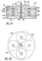
- variable induction coil With reference to FIGS. 3A and 3B, we now describes a first embodiment of a variable induction coil.
- a cylindrical oil circulation tank 44 contains three insulating discs 46, 48, 50 parallel, drilled in their center to allow the passage of an insulating and hollow shaft 52.
- the discs 46 and 50 are fixed to crowns 54, 56 secured to the tank 44.
- the central disc 48 is secured to the axis 52 which fits into a bearing 58 welded or glued to the bottom of the tank 44.
- the axis 52 is provided with a toothed ring fitted into a pinion 62 integral with the axis of a motor 64.
- Each disc 46, 48, 50 supports four flat coils 66 arranged symmetrically with respect to their centers as can be seen in the front view of the disc 48 (FIG. 3B).
- Each winding 66 is wound in an opposite direction with respect to the windings of the neighboring windings.
- the four windings 66 of a disk are connected together in a series connection.
- the windings 66 of the discs 46 and 50 are superimposed, the windings facing each other being wound in the same direction.
- the windings 66 of the discs 46 and 50 are connected in series with each other.
- the windings 66 of the central disc 48 have twice as many windings as the windings 66 of the discs 46, 50.
- the current inlet and outlet wires of the windings of the central disc 48 run through the hollow axis 52 and are connected to insulators placed outside the tank 44.
- the variations in inductance are obtained by modifying, by rotation, the position of the central disc 48.
- the maximum inductance is obtained when the windings supported by the central disc 48 are superimposed on the windings of the discs 46 and 50, the windings of the opposite windings being in the same direction.
- the minimum inductance is obtained by rotating the central disc 48 by 90 ° from the maximum inductance position.
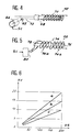
- FIG. 4 schematically represents another embodiment of a coil with variable inductance.
- the variation in inductance is obtained by adjusting the penetration length of a magnetic bar 68 inside the winding 70.
- the bar 68 is integral with a rack 72 fitted into a pinion 62 placed at the end of the axis of a motor 64. In this way, the bar can be driven in translation along the longitudinal axis of the winding 70.
- FIG. 5 schematically represents another embodiment of a variable inductance coil.
- the variation in inductance is obtained by modifying the induction coefficient of a magnetic bar 76 placed inside a coil 74 and along its longitudinal axis.
- a control winding 78 connected to means 80 for delivering a current surrounds the magnetic bar 76.
- the induction coefficient of the magnetic bar 76 and therefore the inductance of the coil 74 depend on the intensity of the current passing through the winding of control 78.
- the winding 74 comprises two series of turns 74a and 74b wound in different directions. In this way, the "transformer" effect of the winding is canceled and, consequently, protection is obtained against possible voltage pulses originating from the reflection of the energy delivered to the tube 18 of the laser, the impedances of the tube 18. and circuit not being perfectly adapted.
- FIG. 6 schematically represents different charge curves relating to an electrical supply device in accordance with that of FIG. 2.
- Curves a, b, c correspond respectively to inductances of 400 mH, 1000 mH and 2000 mH.
- the capacitance of the charge capacitor 20 is 8nF and the repetition frequency of the laser shots is 5 kHz (one shot every 200 microseconds).
- the discharge takes place approximately in 200 ns, which amounts to saying that at the scale adopted in the figure, the discharge curve is substantially vertical.
- the slope of the load curves varies depending on the inductance L of the induction coil 42.
- the voltage reached after 200 microseconds between point A and ground is a function of this slope.
- the power of the laser beam is a direct function of this voltage.
- this adjustment can be automated by means of a servo device referenced 21 in FIG. 2.
- This servo device is described in more detail below with reference to FIG. 7.
- the voltage delivered between point A and earth is controlled by a set value Vc determined by the user.
- a voltmeter 210 measures the voltage applied between point A and mass. This voltmeter performs an average on a hundred measurements for example and delivers on an output a signal indicating the average voltage between point A and ground. This average voltage is compared to the set value Vc by a comparator 212. The latter delivers a signal, function of the comparison, on an input of a control device 214 able to deliver on an output a control signal Sc.
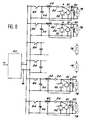
- FIG. 8 schematically represents a device according to the invention applied to the electrical supply of several lasers.
- a single converter 40 converts the alternating voltage of the network into a high direct voltage supplied between its outputs (+) and (-).
- Each of the tubes 18 is connected to a means for delivering a pulse voltage of maximum adjustable amplitude.
- the pulse voltage is adjusted so as to obtain the desired power for each laser beam.
- each of the means for delivering a pulse voltage is in accordance with the embodiment of FIG. 2. These means are all connected in an arrangement parallel to the outputs (+) and (-) of the converter 40. Each of these means is provided with a switch 84 enabling the tube 18 to which they are connected to be put into or out of service.
- the adjustment of the maximum amplitude of the pulse voltage is independent of the conversion of the AC voltage into a DC voltage.
Landscapes
- Physics & Mathematics (AREA)
- Electromagnetism (AREA)
- Engineering & Computer Science (AREA)
- Plasma & Fusion (AREA)
- Optics & Photonics (AREA)
- Lasers (AREA)
- Generation Of Surge Voltage And Current (AREA)
Claims (5)
- Elektrische Versorgungsvorrichtung, insbesondere für einen oder mehrere Metalldampflaser, umfassend:einen einzigen Umformer (40) einer Wechselspannung in eine Gleichspannung mit fester Amplitude, undwenigstens eine Einrichtung, die aus dieser Spannung eine Impulsspannung mit einer regelbaren maximalen Amplitude macht,dadurch gekennzeichnet,daß diese Einrichtung einen steuerbaren Schalter (32) umfaßt, verbunden mit einer Ladeschaltung elektrischer Energie, die eine veränderliche Ladesteilheit aufweist und diese Energie in der Folge der Schließung dieses steuerbaren Schalters (32) entladen kann, unddadurch, daß die Ladung der elektrischen Energie in einem Ladungskondensator (20) erfolgt, verbunden in einem Punkt A mit einer Elektrode einer Diode (24), die verbunden ist mit einer Spule mit variabler Induktion (42), die die Veränderung der Ladesteilheit der Ladeschaltung ermöglicht und deren Induktanz automatisch geregelt wird.
- Vorrichtung nach Anspruch 1, dadurch gekennzeichnet, daß besagte Spule mit variabler Induktion (24) wenigstens zwei Spulen (66) umfaßt, untereinander beweglich und in Serie geschaltet, um eine von ihrer jeweiligen Lage abhängige gegenseitige Induktanz aufzuweisen.
- Vorrichtung nach Anspruch 1, dadurch gekennzeichnet, daß besagte Spule mit variabler Induktion (42) einen in Längsrichtung entsprechend der Spulenachse beweglichen Magnetkern (68) aufweist.
- Vorrichtung nach Anspruch 1, dadurch gekennzeichnet, daß die Spule mit variabler Induktion (42) einen in eine Wicklung (74) eingeführten ferromagnetischen Kern (76) umfaßt, wobei eine Steuerumschlingung (78) den ferromagnetischen Kern (76) umgibt, sowie Einrichtungen (80), die in der Steuerumschlingung (78) einen Strom fließen lassen, um die Induktion des Kerns zu verändern.
- Vorrichtung nach Anspruch 1, dadurch gekennzeichnet, daß sie zusätzlich zu dem genannten Umformer (40) mehrere Einrichtungen zur Lieferung einer Impulsspannung umfaßt, wobei jede Einrichtung mit diesem Umformer verbunden ist.
Applications Claiming Priority (2)
| Application Number | Priority Date | Filing Date | Title |
|---|---|---|---|
| FR9001455 | 1990-02-08 | ||
| FR9001455A FR2658011B1 (fr) | 1990-02-08 | 1990-02-08 | Dispositif d'alimentation electrique pour un ou plusieurs lasers a vapeur metallique. |
Publications (2)
| Publication Number | Publication Date |
|---|---|
| EP0444986A1 EP0444986A1 (de) | 1991-09-04 |
| EP0444986B1 true EP0444986B1 (de) | 1996-09-04 |
Family
ID=9393494
Family Applications (1)
| Application Number | Title | Priority Date | Filing Date |
|---|---|---|---|
| EP19910400280 Expired - Lifetime EP0444986B1 (de) | 1990-02-08 | 1991-02-06 | Elektrische Spannungsversorgungsvorrichtung für einen oder mehrere Metalldampflaser |
Country Status (4)
| Country | Link |
|---|---|
| EP (1) | EP0444986B1 (de) |
| JP (1) | JP2977299B2 (de) |
| DE (1) | DE69121741T2 (de) |
| FR (1) | FR2658011B1 (de) |
Families Citing this family (1)
| Publication number | Priority date | Publication date | Assignee | Title |
|---|---|---|---|---|
| RU2216849C2 (ru) * | 2002-02-05 | 2003-11-20 | Государственное унитарное предприятие "Всероссийский электротехнический институт им. В.И.Ленина" | Высоковольтное коммутирующее устройство |
Family Cites Families (3)
| Publication number | Priority date | Publication date | Assignee | Title |
|---|---|---|---|---|
| US3363184A (en) * | 1963-05-21 | 1968-01-09 | Atomic Energy Commission Usa | Power scavenging deq'ing circuit for a line-type pulser |
| US3749975A (en) * | 1970-08-26 | 1973-07-31 | Wisconsin Alumni Res Found | Adjustable waveform spark source |
| GB2104326B (en) * | 1981-08-08 | 1984-11-21 | Marconi Co Ltd | A pulse generator |
-
1990
- 1990-02-08 FR FR9001455A patent/FR2658011B1/fr not_active Expired - Fee Related
-
1991
- 1991-02-06 DE DE1991621741 patent/DE69121741T2/de not_active Expired - Fee Related
- 1991-02-06 EP EP19910400280 patent/EP0444986B1/de not_active Expired - Lifetime
- 1991-02-07 JP JP3038177A patent/JP2977299B2/ja not_active Expired - Fee Related
Also Published As
| Publication number | Publication date |
|---|---|
| FR2658011A1 (fr) | 1991-08-09 |
| DE69121741D1 (de) | 1996-10-10 |
| FR2658011B1 (fr) | 1997-04-25 |
| JPH04213885A (ja) | 1992-08-04 |
| JP2977299B2 (ja) | 1999-11-15 |
| DE69121741T2 (de) | 1997-03-06 |
| EP0444986A1 (de) | 1991-09-04 |
Similar Documents
| Publication | Publication Date | Title |
|---|---|---|
| FR2565435A1 (fr) | Convertisseur unipolaire de recuperation pour moteur a reluctance commutee utilisant un dispositif principal de commutation par phase | |
| FR2486348A1 (fr) | Circuit d'alimentation de puissance pour une lampe de decharge a haute intensite | |
| FR2463533A1 (fr) | Machine electrique a vitesse variable et a densite reglee du flux magnetique | |
| FR2768273A1 (fr) | Dispositif de conversion de l'energie a butee auto-adaptive et son procede de fonctionnement | |
| EP0444986B1 (de) | Elektrische Spannungsversorgungsvorrichtung für einen oder mehrere Metalldampflaser | |
| EP0125948A1 (de) | Leistungsmodulator mit einem Transformator | |
| FR2726405A1 (fr) | Procede et dispositif de commande de puissance d'une charge via un systeme a reglage de phase | |
| WO1997019508A1 (fr) | Procede et dispositif de compensation des forces d'attraction magnetique a l'interieur d'une machine discoide | |
| FR2558656A1 (fr) | Dispositif pour le demarrage d'un moteur electrique asynchrone | |
| FR2797535A1 (fr) | Dispositif de production d'electricite | |
| EP1344305B1 (de) | Hochspannungsgenerator für elektrostatische farbaufbringungsgeräte | |
| EP0670624A1 (de) | Angepasster Schaltnetzteil zur Niederspannungsschaltung | |
| EP1580873A1 (de) | Vorrichtung und Verfahren zur Steuerung eines Umwandlers und Umwandler und eine solche Vorrichtung enthaltende Elektroinstallation | |
| FR2597285A1 (fr) | Dispositif d'alimentation en courant d'un filament de tube radiogene | |
| CH497073A (fr) | Installation comprenant un générateur de haute tension | |
| FR2961966A1 (fr) | Procede de charge de moyens d'accumulation et dispositif de charge correspondant | |
| FR2466803A1 (fr) | Dispositif pour regler et stabiliser un regulateur de commutation | |
| EP0005107A1 (de) | Vorrichtung und Verfahren zur Energieentnahme aus einer kapazitiven Quelle mit Regelung durch Nebenschlussumschaltung | |
| FR2481530A1 (fr) | Procede et dispositif de production d'impulsions electriques pour le pompage d'un laser | |
| US5202894A (en) | Electric supply device for one or more metal vapor lasers using an electric power charging circuit with a variable inductor to provide a variable charging gradient | |
| EP0540375B1 (de) | Zündungsgenerator mit einer hohen Energie, insbesondere für Gasturbinen | |
| FR3008253A1 (fr) | Demarreur de vehicule automobile | |
| FR2698499A1 (fr) | Circuit pour faire fonctionner une charge inductive. | |
| FR3138019A1 (fr) | Convertisseur DC/DC comprenant deux modules de conversion électrique | |
| EP1283588A2 (de) | Induktor mit Schaltgesteuertem Wert |
Legal Events
| Date | Code | Title | Description |
|---|---|---|---|
| PUAI | Public reference made under article 153(3) epc to a published international application that has entered the european phase |
Free format text: ORIGINAL CODE: 0009012 |
|
| AK | Designated contracting states |
Kind code of ref document: A1 Designated state(s): DE GB NL |
|
| 17P | Request for examination filed |
Effective date: 19920207 |
|
| 17Q | First examination report despatched |
Effective date: 19940727 |
|
| GRAH | Despatch of communication of intention to grant a patent |
Free format text: ORIGINAL CODE: EPIDOS IGRA |
|
| GRAH | Despatch of communication of intention to grant a patent |
Free format text: ORIGINAL CODE: EPIDOS IGRA |
|
| GRAA | (expected) grant |
Free format text: ORIGINAL CODE: 0009210 |
|
| AK | Designated contracting states |
Kind code of ref document: B1 Designated state(s): DE GB NL |
|
| REF | Corresponds to: |
Ref document number: 69121741 Country of ref document: DE Date of ref document: 19961010 |
|
| GBT | Gb: translation of ep patent filed (gb section 77(6)(a)/1977) |
Effective date: 19961122 |
|
| PLBE | No opposition filed within time limit |
Free format text: ORIGINAL CODE: 0009261 |
|
| STAA | Information on the status of an ep patent application or granted ep patent |
Free format text: STATUS: NO OPPOSITION FILED WITHIN TIME LIMIT |
|
| 26N | No opposition filed | ||
| PGFP | Annual fee paid to national office [announced via postgrant information from national office to epo] |
Ref country code: NL Payment date: 20000229 Year of fee payment: 10 |
|
| PG25 | Lapsed in a contracting state [announced via postgrant information from national office to epo] |
Ref country code: NL Free format text: LAPSE BECAUSE OF NON-PAYMENT OF DUE FEES Effective date: 20010901 |
|
| NLV4 | Nl: lapsed or anulled due to non-payment of the annual fee |
Effective date: 20010901 |
|
| REG | Reference to a national code |
Ref country code: GB Ref legal event code: IF02 |
|
| PGFP | Annual fee paid to national office [announced via postgrant information from national office to epo] |
Ref country code: GB Payment date: 20020206 Year of fee payment: 12 |
|
| PGFP | Annual fee paid to national office [announced via postgrant information from national office to epo] |
Ref country code: DE Payment date: 20020419 Year of fee payment: 12 |
|
| PG25 | Lapsed in a contracting state [announced via postgrant information from national office to epo] |
Ref country code: GB Free format text: LAPSE BECAUSE OF NON-PAYMENT OF DUE FEES Effective date: 20030206 |
|
| PG25 | Lapsed in a contracting state [announced via postgrant information from national office to epo] |
Ref country code: DE Free format text: LAPSE BECAUSE OF NON-PAYMENT OF DUE FEES Effective date: 20030902 |
|
| GBPC | Gb: european patent ceased through non-payment of renewal fee |