EP0444536A2 - Telephone exchange system and method - Google Patents
Telephone exchange system and method Download PDFInfo
- Publication number
- EP0444536A2 EP0444536A2 EP91102563A EP91102563A EP0444536A2 EP 0444536 A2 EP0444536 A2 EP 0444536A2 EP 91102563 A EP91102563 A EP 91102563A EP 91102563 A EP91102563 A EP 91102563A EP 0444536 A2 EP0444536 A2 EP 0444536A2
- Authority
- EP
- European Patent Office
- Prior art keywords
- recording
- telephone
- voice
- exchange system
- control means
- Prior art date
- Legal status (The legal status is an assumption and is not a legal conclusion. Google has not performed a legal analysis and makes no representation as to the accuracy of the status listed.)
- Granted
Links
Images


Classifications
-
- H—ELECTRICITY
- H04—ELECTRIC COMMUNICATION TECHNIQUE
- H04M—TELEPHONIC COMMUNICATION
- H04M3/00—Automatic or semi-automatic exchanges
- H04M3/42—Systems providing special services or facilities to subscribers
- H04M3/50—Centralised arrangements for answering calls; Centralised arrangements for recording messages for absent or busy subscribers ; Centralised arrangements for recording messages
- H04M3/53—Centralised arrangements for recording incoming messages, i.e. mailbox systems
- H04M3/533—Voice mail systems
-
- H—ELECTRICITY
- H04—ELECTRIC COMMUNICATION TECHNIQUE
- H04M—TELEPHONIC COMMUNICATION
- H04M3/00—Automatic or semi-automatic exchanges
- H04M3/42—Systems providing special services or facilities to subscribers
-
- H—ELECTRICITY
- H04—ELECTRIC COMMUNICATION TECHNIQUE
- H04M—TELEPHONIC COMMUNICATION
- H04M2201/00—Electronic components, circuits, software, systems or apparatus used in telephone systems
- H04M2201/38—Displays
-
- H—ELECTRICITY
- H04—ELECTRIC COMMUNICATION TECHNIQUE
- H04M—TELEPHONIC COMMUNICATION
- H04M3/00—Automatic or semi-automatic exchanges
- H04M3/42—Systems providing special services or facilities to subscribers
- H04M3/487—Arrangements for providing information services, e.g. recorded voice services or time announcements
-
- H—ELECTRICITY
- H04—ELECTRIC COMMUNICATION TECHNIQUE
- H04M—TELEPHONIC COMMUNICATION
- H04M3/00—Automatic or semi-automatic exchanges
- H04M3/42—Systems providing special services or facilities to subscribers
- H04M3/50—Centralised arrangements for answering calls; Centralised arrangements for recording messages for absent or busy subscribers ; Centralised arrangements for recording messages
- H04M3/53—Centralised arrangements for recording incoming messages, i.e. mailbox systems
- H04M3/537—Arrangements for indicating the presence of a recorded message, whereby the presence information might include a preview or summary of the message
Abstract
Description
- This invention relates to a telephone exchange system which accommodates a plurality of main lines and a plurality of telephones. More particularly, the invention relates to a telephone exchange system in which the audio of a telephonic communication is recorded in a recording area shared by a plurality of telephones, and the recorded audio is played back by any of the telephones or transferred.
- In a conventional telephone exchange system, telephones each having a recording/playback function are used as extension telephones connected to the system in order to record the audio of a telephonic communication that is in progress. This makes it possible for each extension to individually record and/or playback the audio of the communication. In another conventional telephone exchange system, the system is provided with a memory device shared by each extension telephone, the storage area of the memory device is divided among the extensions, and a telephonic communication is recorded in or played back from an area that has been designated from an extension telephone by an operation performed at this telephone.
- If the former arrangement having a recording/playback function for every extension is adopted, it raises the cost of the telephone exchange system. In order to convey the contents of a recording as is from one extension telephone to another, a troublesome operation is required in which the recording medium such as a recording tape is handed over to the party for which the message is intended or the recording is re-recorded on the recording medium possessed by this party.
- In the latter case where the storage area of one memory device is apportioned to each of a plurality of extension telephones and used to record and/or playback a telephonic communication, the storage areas used are fixedly assigned to the telephones. Consequently, the storage capacity for a particular user may be inadequate or, even if the storage capacity for a user is more than enough, it cannot be used by another telephone. Thus, the storage areas cannot be effectively exploited by the system as a whole.
- Further, in conventional telephone exchange systems, when a message is requested to be delivered to someone who is absent, and the party who is to receive the message happens to return to the location of his or her own telephone while the recording is in progress, this individual may not know that the message intended for him or her is being recorded and will not be able to engage the calling party who is in the process of leaving the message.
- In addition, since the starting time of a recording cannot be determined in conventional telephone exchange systems, one may not respond soon enough to a recorded message, to the detriment of a commercial transaction or the like.
- Accordingly, an object of the present invention is to provide an inexpensively constructed telephone exchange system in which efficient use is made of a recording/playback memory shared by each extension telephone accommodated by the exchange system, thereby raising degree of freedom in terms of recording/playback and improving service.
- Another object of the present invention is to provide a telephone exchange system in which a party to receive a message is capable of knowing that the message is in the process of being recorded, thereby making it possible for this party to respond to the party leaving the message.
- According to the present invention, the foregoing objects are attained by providing a telephone exchange system comprising recording control means for controlling the starting and stopping of recording of a voice on recording means, managing means for managing the recording operation of the recording means, specific-information storing means for storing, based upon results of management performed by the managing means, at least recording area information, telephone-specifying information, recording starting-position information and recording end-position information as information specifying a recording, altering means for altering information, which has been stored in the specific-information storing means, in accordance with a change in the information specifying recording based upon the management performed by the managing means, erasing means for erasing a recording on the recording means after the recording is transferred in response to a transfer request, voice detecting means for detecting whether a voice is present during a telephone call, means for starting or stopping recording of the voice by the recording means based upon results of detection performed by the voice detecting means, recording sensing means for sensing whether there is a recording for a specific telephone based upon results of management performed by the managing means, display means for displaying, on the specific telephone, and based upon the results of sensing performed by the recording sensing means, a message to the effect that there is a recording for this specific telephone, acknowledging means for acknowledging a connect request from the specific telephone while the recording means is recording a voice, and connection control means for connecting the telephone which has issued the connect request and the calling party when the acknowledging means acknowledges the connect request.
- Still another object of the present invention is to provide a telephone exchange system in which, when a recording is played back, the time at which the recording was made is announced by voice, thereby enhancing the reliability of recorded information.
- According to the present invention, the foregoing object is attained by providing a telephone exchange system comprising recording control means for controlling the starting and stopping of recording of a voice on recording means, managing means for managing the recording operation of the recording means, recording specifying means for specifying a recording in the recording means based upon results of management performed by the managing means, telephone specifying means for specifying a telephone among a plurality of telephones based upon results of management performed by the managing means, playback control means for playing back the recording, which has been specified by the recording specifying means, by the telephone specified by the telephone specifying means, timekeeping means for clocking time, and converting means for converting time clocked by the timekeeping means into an audible voice.
- Other features and advantages of the present invention will be apparent from the following description taken in conjunction with the accompanying drawings, in which like reference characters designate the same or similar parts throughout the figures thereof.
-
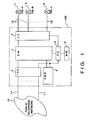
- Fig. 1 is a block diagram illustrating the overall construction of a first embodiment of a telephone exchange system according to the present invention;
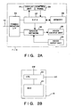
- Fig. 2A is a block diagram illustrating the construction of an extension telephone connected to the telephone exchange system;
- Fig. 2B is a block diagram showing the internal construction of a voice-message controller;
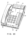
- Fig. 2C is an external view of the extension telephone connected to the telephone exchange system;
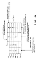
- Fig. 3 is a diagram showing a management index table of a voice memory;
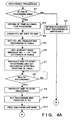
- Fig. 4 is a flowchart illustrating a processing procedure for recording of a voice message during a telephone call according to the first embodiment;
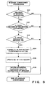
- Fig. 5 is a flowchart illustrating a processing procedure for playing back a voice message according to the first embodiment;
- Fig. 6 is a flowchart illustrating a processing procedure for conveying a voice message according to the first embodiment;
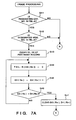
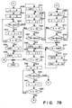
- Fig. 7 is a flowchart illustrating a processing procedure for erasing a recorded voice message according to the first embodiment;
- Fig. 8 is a flowchart illustrating modification of a processing procedure for conveying a voice message according to the first embodiment;
- Fig. 9 is a block diagram illustrating the internal construction of a voice-message controller according to a second embodiment of the present invention;
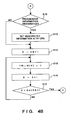
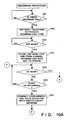
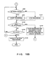
- Fig. 10 is a flowchart illustrating a recording processing procedure according to the second embodiment;
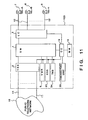
- Fig. 11 is a block diagram illustrating the overall construction of a third embodiment of a telephone exchange system according to the present invention;
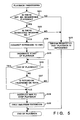
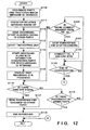
- Fig. 12 is a flowchart illustrating a call processing procedure according to the third embodiment;
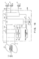
- Fig. 13 is a block diagram illustrating the overall construction of a fourth embodiment of a telephone exchange system according to the present invention;
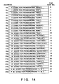
- Fig. 14 is a diagram showing the construction of a time-stamp ROM;
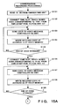
- Fig. 15 is a flowchart illustrating a call recording processing procedure according to the fourth embodiment;
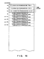
- Fig. 16 is a diagram showing the construction of a voice memory according to the fourth embodiment;
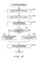
- Fig. 17 is a flowchart illustrating an operation for playing back a recording according to the fourth embodiment; and
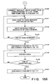
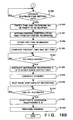
- Fig. 18 is a flowchart illustrating a modification of the operation for playing back a recording according to the fourth embodiment.
- Fig. 1 is a block diagram showing the overall construction of a telephone exchange system according to a first embodiment of the present invention.
- The telephone exchange system, indicated at
numeral 100, includes a switch circuit network (SW) 1 for performing time-division switching, a trunk circuit unit (TRK) 2 which interfaces a plurality ofline wires 11 accommodated in thesystem 100 and connected to apublic telephone network 10, a line circuit (LC) 3 having an interface forextensions 12, a memory (MM) 4 for storing a control program and data, a central controller (CC) 5 for controlling the overall system, and a voice message controller (VMR) 6 which, in response to instructions from theCC 5, applies predetermined processing, described later, to voice information handled by the telephone exchange system. Extension telephones 7 through 9 are connected to theLC 3 via theextensions 12. - Fig. 2A is a block diagram showing the construction of the extension telephones, which are private telephones connected to the
telephone exchange system 100. Each of the extension telephones 7 through 9 includes acommunication interface 24 for connecting channels to thetelephone exchange system 100 and communicating control data between the telephones and the exchange system, adisplay unit 31 for displaying dialed numbers, messages and the like, aCPU 27 comprising a microprocessor which controls the overall operation of theextension telephones 7 through 9, acontrol panel 25 comprising dial buttons or the like, amemory 26 which stores a program that decides the operation of theCPU 27 as well as control information such as information necessary for operation of theextension telephones 7 through 9, avoice input unit 28 comprising a microphone or transmitter, and avoice output unit 29 comprising a speaker or receiver. - Fig. 2B is a block diagram illustrating the internal construction of the
voice message controller 6 constituting part of thetelephone exchange system 100. - The
voice message controller 6 is provided with a voice memory (REC) 21 constituted by a semiconductor memory for storing a recorded voice, and a voice controller (CTL) 22 which controls the recording and playback operations of the voice memory. - More specifically, when recording is performed, the
voice controller 22 starts recording a voice, which is received from theswitch circuit network 1, from a recording starting position in thevoice memory 21 designated by thecentral controller 5, and continues the recording operation until the end is designated by thecentral controller 5. After the recording operation is ended by the end designation, thecentral controller 5 is informed of the recording end position in thevoice memory 21. - When playback is performed, the
voice controller 22 plays back the voice data from the starting position to the end position of thevoice memory 21 designated by thecentral controller 5. Thevoice controller 22 outputs the played back voice data to theswitch circuit network 1 and, at the conclusion of playback, so informs thecentral controller 5. - Fig. 2C is an external view of the
extension telephones 7 through 9 connected to the telephone exchange system of this embodiment. As shown in Fig. 2C, each of theextension telephones 7 through 9 includes a ten-key pad 43 serving as a control panel, a line-wire selecting key 44, arecording key 45, ahold key 46, and aspeaker 42 serving as a voice output unit. Ahandset 41 functions as both a voice output unit and a voice input unit. - Fig. 3 is a diagram showing a management index table of the
voice memory 21. - In the illustrated embodiment, the
voice memory 21 is managed by being divided into storage areas (hereinafter referred to as "blocks") of four-second units serving as recording time. The management index table comprises a table A (TBL-A) shown in Fig. 3a and a table B (TBL-B) shown in Fig. 3B. - The table A has records R0 through Rn. The record R0 comprises a counter (CNT1) the value of which represents the block number of the next recording starting position, and a counter (CNT2) the value of which represents the number of blocks capable of being recorded on consecutively from the recording starting position. The records R1 through Rn are constituted by an extension number (D1) serving as information indicating the possessor of a recorded voice message, a message number (D2) for specifying individual voice messages for the same possessor, a block number (D3) which indicates the recording starting position of the voice message within the
voice memory 21, and a block number D4 which indicates the recording end position of the voice message within thevoice memory 21. - The table B indicates the status of use of every block. If the status of a block is that the block is unused, this is indicated by a "0"; if the status of a block is that the block is being used, this is indicated by a "1".
- In Fig. 3B, blocks 0 - 2 indicate that the possessor of extension number "10" has been recorded as
message number 01; blocks 3 - 5 indicate that the possessor of extension number "11" has been recorded asmessage number 01 and blocks 6 - 7 indicate that the same possessor has been recorded asmessage number 02 has been recorded; and blocks 10 - 11 indicate that the possessor of extension number "13" has been recorded asmessage number 01. The remainingblocks block 12, and a maximum of four blocks, namely 16 seconds of conversation, can be recorded, as record R0 indicates in Fig. 3A. - The processing procedure for a voice message in accordance with this embodiment will now be described.
- Fig. 4 is a flowchart illustrating a processing procedure for recording a voice message while a call is in progress.
- Assume that a special number (e.g., 80) which requests the start of recording has been dialed in from the extension telephone 7 (TEL-A) while this telephone is engaged in a call via a line wire. This request is sent to the
central controller 5 via theline circuit 3. - At step S1 of the flowchart, the
central controller 5 checks to determine whether an area capable of being recorded in is available in the voice memory 21 (i.e., whether CNT2 = 0 holds). If there are no blank areas, the extension telephone which has made the recording request is informed, as by an audible tone or visible display, of the fact that recording is impossible (step S2). - If recording is possible, the extension telephone is informed, from the value of CNT2, of the amount of time available for recording (step S3). The
central controller 5 connects the line wire involved in the call and thevoice message controller 6 via the switch circuit network 1 (step S4). - Next, the
central controller 5 searches for a blank record in the table A. In the example illustrated in Fig. 3A, the extension number (assumed to be "10") of the extension telephone which has made the recording request is stored at D1 of record R5 (step S5). Next, "10" is searched from D1 of each record in table A, the maximum value among the already used message numbers is retrieved, one is added to this value and the sum is set at D2 of record R5. In this example, "2" is set (step S6). - The
central controller 5 then instructs thevoice message controller 6 to start recording from the position indicated at CNT1, and sets this recording starting position at D3 of record R5 in table A (step S7). In this example, "12" is set. - The system then waits for a recording-end request from the extension telephone (step S8). This request is made using a special number (e.g., 81) entered from the extension telephone, in the same manner as the request for starting recording. If the
central controller 5 has received the recording-end request transmitted via theline circuit 3, then it instructs thevoice message controller 6 to terminate the recording (step S9). - Upon receiving the recording end position from the
voice message controller 6, thecentral controller 5 sets this position at D4 of record R5 (step S10) and opens the connection between thevoice message controller 6 and the line wire 11 (step S11). - The record R5 is completed by the foregoing processing. It should be noted that the extension telephone which has made the recording request (its extension number is "10" in this case) is the possessor of the recorded message, however, the possesor can be designated when the recording ends. For example, this can be done if the pertinent extension number is dialed in following the special number "81" mentioned above.
- If possessor information is designated (step S12), D1 of record R5 is changed by the
central controller 5 to what has been designated (step S13). - Next, the table B is updated. It should be noted that X in the flowchart indicates a working counter.
- First, the block number of the currently prevailing recording starting position is set in the counter X (step S14), and the value of the position in table B indicated by the counter X is made "1", which indicates that recording has been completed (step S15). Next, one is added to counter X (step S16), and the value in counter X is compared with the value of D4 (step S17). Steps S14 and S15 are repeated until it is determined that the position is the recording end position. When the updating of table B ends, processing for updating CNT1 and CNT2 is carried out. This processing will be described later.
- In order to maintain confidentiality, it is assumed here that in principle the voice message can only be played back by the extension telephone indicated at D1 of each record in table A. In order for a playback request to be made by the extension telephone, it will suffice to dial in a special number indicative of a playback request as well as the message number after the telephone is taken off the hook.
- It should be noted that the
central controller 5 instructs the extension telephone where the voice message is to be played back, to display the fact that there is the message stored to the telephone and the message number associated with it. - Fig. 5 is a flowchart for describing processing in a case where a playback request is received.
- The
central controller 5 determines whether a voice message possessed by the extension telephone which has issued the playback request is present in the table A (step S21) and checks to see whether the requested message number is present (S22) in table A. If these are not present in table A, then the program proceeds to step S23, where thecentral controller 5 informs the requesting extension telephone, by means of an audible tone or visual display, of the fact that playback is impossible. Processing is then terminated. - If a requested voice message does exist, however, the
voice message controller 6 is connected, via theswitch circuit network 1, to the extension which has issued the request (step S24). Thecentral controller 5 then obtains the playback starting and end positions from D3 and D4 of the record in table A that match the playback request, and thevoice message controller 6 is instructed to perform playback based upon these positions (step S25). Next, while the system waits for the end of playback from thevoice message controller 6, monitoring is performed to determine if the extension telephone which has made the playback request has been hung up (steps S26, S27). If the latter is detected, thevoice message controller 6 is instructed to terminate playback (step S28), and the connection between thevoice message controller 6 and the requesting extension is opened (step S29). - Thus, a voice of a telephonic communication in progress can be recorded and played back from any extension telephone.
- Next, a case will be described in which a voice message already recorded by applying steps S12, S13 (Fig. 4B) at the time of recording is played back by another extension telephone. For example, in a case where a message intended for the possessor of extension telephone (extension number assumed to be "12") is recorded by the foregoing method at extension telephone (extension number assumed to be "11") and the possessor of the pertinent recorded voice message is extension telephone "11", the message can be conveyed by the method shown in Fig. 6.
- First, after the extension telephone "11" is taken off the hook, a special number requesting conveyance of the message, the message number and the extension number "12" which is the destination of the message are dialed in. When there is such a request for conveyance of a message (YES at step S31), it is verified at step S32 whether the record corresponding to the extension telephone "11", which is the extension telephone making the request, is present in table A, and then it is verified at step S33 whether the designated message number is present in table A. If the answer is YES at steps S32 and S33, then D1 of the pertinent record is changed to the designated extension number "12"(step S34), and the message number also is updated in dependence upon the changed extension number (step S35). Upon completion of such updating, the extension telephone that has newly become the possessor of the voice message is informed, by an audible tone or visible display, of the fact that there is a message to be conveyed (step S36). Processing for conveyance of the message is then terminated.
- On the other hand, if the possessor of the extension telephone "12" informed of the fact that there is a message performs the above-described playback operation, this telephone can play back the voice message intended for it.
- In the foregoing processing, rather than entering a specific extension number as the destination of a message, e.g., "00" can be entered to designate all extensions, or "01" - "09" can be entered to designate separately determined groups of extensions, in which case the designated extensions would become the destination of the message to be conveyed. With such an arrangement, the extension telephone "11" could receive a message from a superior outside the office, and this message could then be delivered to all of the extensions. The same is true for the operation at step 13 (Fig. 4B)
- Fig. 7 is a flowchart illustrating processing for erasing an already recorded voice message.
- Erasing of a voice message is carried out based upon dialing in, from an extension telephone, a special number requesting erasure and a message number.
- First, the
central controller 5 verifies whether a record matching the requesting extension number and the designated message number is present in table A (steps S41, S42). If the record is not present, this processing is terminated. If the abovementioned numbers are present, however, D1, D2 of the pertinent record are cleared (step S43) and table B is updated by making "0" the status of use of this block in table B, which is indicated by D3 of the pertinent record (step S44). ("0" means that the block is not being used.) The value of D3 is then incremented (step S45), and the processing which makes the pertinent blocks of table B "0" is continued until the value of D3 exceeds a value corresponding to the position indicated by D4 of the pertinent record (step S46). - When all of the pertinent blocks of table B have been made "0", D3 and D4 are cleared (step S47) and a transition is made to processing for updating CNT1 and CNT2. In the description that follows, n represents a working counter which corresponds to block position in the table B, m represents a working counter which represents the number of blocks in a non-utilized state.
- First, the counters n, m are initialized to "0" (steps S50, S51) and a search is performed successively from 0 in order to detect blocks not being used (steps S52, S53, S54). If there are no unused blocks over the total number of blocks, the values of counters n, m are set in CNT1, CNT2, respectively (steps S55, S56). This indicates that CNT1, CNT2 are both "0", meaning that the entirety of the
voice memory 21 has been used up. - If an unused block has been found in table B at step S52, then the value of n prevailing at this time is set in CNT1 (step S57). Counter m is then incremented (step S58) and the number of consecutive unused blocks is counted (steps S58, S59, S60, S61).
- When it is determined at step S60 that the value of n has exceeded 15, indicating that the end of table B has been reached, or when it is determined at step S61 that there are no unused blocks, the value in counter m is set in CNT2 (step S56 or S62). After the processing of step S62, the counter n is incremented (step S63). If the search has reached the end of table B, i.e., if the decision rendered at step S64 is NO, then processing is terminated.
- On the other hand, if it is decided at step S64 that the search has not reached the end of table B, then the program proceeds to step S65, where counter m is initialized to "0", and unused blocks are retrieved (steps S66, S67, S68) just as in steps S52 through S54 above.
- If an unused block is found at step S66, the number of consecutive unused blocks is counted (steps S69, S70, S71) just as in steps S58 through S61 above.
- If it is decided at step S71 that the end of table B has been reached, or if an unused block is found at step S72, then the program proceeds to step S73, where the number m of blocks just counted and the block count CNT2 counted last are compared. If m is greater, the program proceeds to step S74, where the value of m is set in CNT2. Next, a value obtained by subtracting m from the present block position n is set in CNT1 (step S75) as the recording starting position which corresponds to CNT2. The program then proceeds to step S63 and processing is repeated up to the end of the table B.
- By virtue of the foregoing processing, the maximum number of consecutive blocks in an unused state in
voice memory 21 can be set in CNT2 and the number of the recording starting block can be set in CNT1 at the same time. - In accordance with the first embodiment, as described above, a memory which stores voice messages and an index for managing individual voice messages in the entire memory are provided, the memory is shared mutually by the extension telephones connected to the system, and the memory is managed upon being divided into units of minimum capacity sufficient for ordinary recording purposes. The following advantages are obtained:
- (1) It is unnecessary to make a copy of a voice message, which has been recorded in the memory, for the purpose of delivering the message to another party, and no increase in the capacity of the memory is required. This means that there is no increase in the cost of the system.
- (2) A change in the possessor information in the index is performed in exact fashion, and processing for conveying a message to a third party can be performed simply while maintaining confidentiality.
- (3) Recording always can be performed for the maximum recordable period of time in dependence upon the status of use of the memory when a telephone conversation is recorded, and the memory can be exploited efficiently.
- (4) Even if recording and playback are repeated, only enough memory capacity needed for recording is set aside, and the memory can be used effectively without leaving areas in the memory that are incapable of being used.
- Furthermore, in the present embodiment, requests for starting and ending recording and playback, a request for erasure, etc., are capable of being made by dialing in special numbers from an extension telephone. However, an arrangement can be adopted in which the extension telephone is provided with function buttons corresponding to these various requests.
- In addition, if the number of voice messages that can be recorded per extension telephone is limited to one, the message numbers used in the embodiment can be omitted.
- Further, the possessor information is not limited to extension numbers. For example, use can be made of other information specifying a particular individual, such as the physical location at which the telephone has been installed, an employee number at the time or recording, etc. Moreover, by additionally designating a password at the time of recording and requesting input of the password at the time of playback, confidentiality can be better protected. All of these options can be realized with facility by expanding the possessor information in table A.
- If the capacity of the
voice memory 21 and the units of the blocks are of the minimum necessary capacity needed to record a single telephonic communication, these values may be set as desired, and the size of the table B can be changed accordingly. Thevoice memory 21 can be a magnetic tape instead of a semiconductor memory, and it will suffice if the information recorded on these media is information indicative of starting- and end-positions in table A. - Furthermore, though the present embodiment deals with voice messages from outside line wires, an arrangement can be adopted in which voice messages between extensions are also recorded.
- In the first embodiment described above, processing for delivering a message is such that the possessor of extension telephone "11" performs a prescribed operation to inform the extension telephone "12" of the fact that there is a message to be delivered. A modification of this embodiment will now be described with reference to the flowchart of Fig. 8.
- After the extension telephone "11" is taken off the hook, a special number requesting conveyance of the message, the message number and the extension number which is the destination of the message are dialed in from extension telephone "11". When there is such a request for conveyance of a message (YES at step S81), the
central controller 5 verifies at step S82 whether the record corresponding to the extension telephone "11", which is the extension telephone making the request, is present in table A, and then verifies at step S83 whether the designated message number is present in table A. If the answer is YES at steps S82 and S83, then D1 of the pertinent record is changed to the designated extension number (step S84), and the message number also is updated in dependence upon the changed extension number (step S85). Upon completion of such updating, the extension telephone that has newly become the possessor of the voice message is informed, by an audible tone or visible display, of the fact that there is a message to be conveyed (step S86). - At the same time, the
central controller 5 starts, via theline circuit 3, a recording/playback unit (not shown) belonging to the extension telephone "12", and transfers the voice data, that has been stored in thevoice memory 21, to this recording/playback unit (step S87). Next, at step S88, it is determined whether the transfer has ended. If the answer is YES, then the voice data in thevoice memory 21 is erased at the ensuing step S89. It should be noted that this erasing processing is the same as that illustrated in Fig. 7 and therefore need not be described again. - The possessor of extension telephone "12", which has received the transfer of voice data, is capable of determining, by the aforementioned audible tone or visible display, that there is a message to be delivered to this telephone. By performing a prescribed operation, the possessor of this telephone is capable of hearing the contents of the message.
- Thus, this modification is such that in a telephone exchange system having a function for recording a telephonic communication for the purpose of allowing it to be heard by a third party, it is no longer necessary to hold all recordings in a memory within the system. This makes it possible to reduce the necessary memory capacity that is provided within the system for the purpose of voice recording/playback, and to effectively utilize any extra memory area for other applications.
- A second embodiment of the present invention will now be described. It should be noted that the construction of the telephone exchange system according to this embodiment is the same as that of the first embodiment and therefore need not be described again.
- Fig. 9 is a block diagram illustrating the internal construction of the voice message controller constituting the telephone exchange system of the second embodiment. As shown in Fig. 9, a
voice detector 23 is for detecting the absence or presence of a voice during a telephonic communication. Thevoice detector 23 determines that there is a voice present only when a voice above a predetermined level continues in excess of a predetermined period of time. The result of this determination is delivered to thecentral controller 5. - Fig. 10 is a flowchart illustrating recording processing according to the second embodiment.
- The
central controller 5 monitors an incoming-call signal fromline wire 11 via thetrunk circuit 2. When there is an incoming call (YES at step S91), apredetermined extension telephone 7 is made to issue an incoming-call tone (step S92) and theline circuit 3 is actuated to monitor whether theextension telephone 9 has been taken off the hook (step S93). - When it is detected that the
extension telephone 9 has been taken off the hook, thetrunk circuit 2 is actuated to close a loop in theline wire 11, and theswitch circuit network 1 is controlled to connect a channel between theline wire 11 andextension telephone 9, thereby establishing a state of communication (step S94). Next, monitoring of the end of the call (step S95) and monitoring of a recording-start operation (step S96) is performed repeatedly. - When it is detected at step S95 that the
extension telephone 9 has been hung up, on-hook processing is executed (step S105) and this cycle of processing is terminated. - On the other hand, when a recording-start operation from the
extension telephone 9 is detected by theline circuit 3, thecentral controller 5 instructs thevoice controller 22 to connect theswitch circuit network 1 and thevoice memory 21 in order that a recording may be made, and to connect theswitch circuit network 1 and thevoice detector 23 in order that a voice may be detected. A recording-standby state is thus established (step S97). - When the
voice detector 23 detects a voice in a telephonic communication (step S98), thecentral controller 5 actuates thevoice controller 22, which responds by starting recording (step S99). As a result, voice data from theline wire 11 is stored in thevoice memory 21. However, when thevoice detector 23 cannot detect a voice, thevoice controller 22 is actuated to halt the recording operation (step S101). - Next, when a recording-end operation from the
extension telephone 9 is detected via the line circuit 3 (step S102), thecentral controller 5 actuates thevoice controller 22 to halt the recording operation and controls theswitch circuit network 1 to break the connection between theswitch circuit network 1 andvoice memory 21 and between theswitch circuit network 1 andvoice detector 23, thereby establishing the voice data, which has been stored in thevoice memory 21, as one message to be delivered (step S103). Thereafter, on-hook monitoring is performed at step S95. - On the other hand, in a case where it is detected that the
extension telephone 9 has been hung up without detecting the recording-end operation (step S104), on-hook processing is executed (step S105) and this cycle of processing is terminated. When hanging up of the telephone is not detected, the program returns to step S98, where it is determined whether or not a voice is present. - It is permissible to adopt an arrangement in which, when it is detected at step S104 that the phone is on the hook, the on-hook processing is not executed immediately but is instead executed after the voice data, which has been stored in the
voice memory 21, has been established as one message to be delivered. - Further, an arrangement can be adopted in which the operation of the
voice detector 23 is halted, i.e., the connection between thevoice detector 23 and theswitch circuit network 1 is broken, the possessor of theextension telephone 9 determines himself whether there is a voice and then either starts recording or stops recording. By adopting such an arrangement, the speaker can start or stop recording based upon whether the subject matter of the conversation is important or not. - In accordance with the second embodiment, as described above, the arrangement is such that if the voice of the other party is recorded during a telephonic communication, recording can be stopped when the other party is not speaking. This makes it possible to utilize the voice storage area effectively.
- A third embodiment of the present invention will now be described.
- Fig. 11 is a block diagram illustrating the overall construction of a telephone exchange system according to the third embodiment. Elements identical with those in the telephone exchange system of the first embodiment are designated by like reference characters and need not be described again.
- In Fig. 11, the
telephone exchange system 100 includes aguidance signal generator 33 which, upon receiving an instruction from thecentral controller 5, generates a guidance signal, which is indicative of the start of recording, to the other party in a conversation via theswitch circuit network 1, asound source 34 which generates an audible tone at theextension telephones 7 through 9 and at the other party, and atimekeeping unit 35 which, in accordance with an instruction from thecentral controller 5, performs a timekeeping operation to inform thecentral controller 5 of the result of timekeeping, namely when time has run out, etc. - Fig. 12 is a flowchart illustrating a call processing procedure according to the third embodiment.
- When, during communication between the
line wire 11 and theextension telephone 7, the party engaged in the conversation with theextension telephone 7 reports to the speaker onextension telephone 7 that there is a message to be relayed to the possessor of theextension telephone 8, who is absent, the speaker onextension telephone 7 first presses a key for designating theextension telephone 8, namely the party for which the message is intended (step S110), and then performs an on-hook operation, such as hanging up the handset (step S111). This is the operation to relay the message. - After it is detected that the person performing the message relaying operation has hung up, the
central controller 5 of thetelephone exchange system 100 actuates theguidance signal generator 33 so that a guidance signal indicative of the start of recording is transmitted to the other party (step S112). Also, thetimekeeping unit 35 is started (step S113). In addition, the voice message controller is actuated to start recording, and the voice is stored in thevoice memory 21 along with information designating the party for which the message is intended (step S114). - Next, when the
central controller 5 sends a predetermined signal to theextension telephone 8, which is the party for which the message is intended, theextension telephone 8 causes thedisplay unit 31 to present a display to the effect that the message is being recorded (step S115). - Thereafter, the
central controller 5 determines whether a time-out signal, which indicates that a preset period of time has elapsed, has been generated by the timekeeping unit 35 (step S116). If the time has run out, theguidance signal generator 33 is actuated again to transmit a guidance signal to the other party (step S117). This is guidance which indicates to this party that the time for recording is at an end. Recording is then terminated at step S118. - If the time has not run out, it is determined at step S119 by the
central controller 5 whether the other party terminated the call. If the answer at step S119 is YES, then the program proceeds to step S118 and recording is ended. - However, if the other party has not terminated the call, then it is determined by the
central controller 5 whether a connect request has been made by theextension telephone 8, which is the party that is to receive the message. Here the determination as to whether a connect request has been made is performed by detecting input of a password specifically assigned to each of the system extension telephone users or merely by detecting that this extension telephone has been taken off the hook. - If it is determined at step S120 that a connect request has been made, the
central controller 5 halts the timekeeping operation of thetimekeeping unit 35 and the recording in the voice memory 21 (step S121), and then makes a connection between theextension telephone 8 and the other party, namely the party that requested delivery of the message (step S122). - If it is determined at step S120 that a connect request has not been made, the program returns to step S116 and processing for determining whether the time-out signal is present or not is continued.
- Thereafter, in a case where the possessor of
extension telephone 8 learns, from the display ondisplay unit 31, that there is a message intended for this extension telephone, the possessor performs a prescribed operation to extract and listen to the contents of the message. This operation is the same as that for requesting playback set forth in the first embodiment and need not be described again. - It should be noted that the indication given at step S115 informing of the fact that recording is in progress need not be presented using the
display unit 31. For example, this indication can be made by flashing an LED belonging to a line-wire select/status display button constituting part of thecontrol panel 25. The flashing of the LED in this case would have a period different from that indicating that a call is on hold. In addition, if the LED is capable of emitting light having two or more colors, the fact that the display is one indicating that recording is in progress can be distinguished by color. - In accordance with the third embodiment, as described above, the arrangement is such that if a party for whom a message is intended returns to the location of his or her own extension telephone while recording of the message is in progress, and if this party then realizes from the display that recording of this message is in progress and responds by issuing a connect request from his or her own extension telephone, then this extension telephone and the party attempting to convey the message are connected, thereby making it possible for the two parties to promptly carry on a conversation.
-
- A fourth embodiment of the present invention will now be described.
- Fig. 13 is a block diagram illustrating the overall construction of a telephone exchange system according to the fourth embodiment. Elements identical with those in the telephone exchange system of the first embodiment are designated by like reference characters and need not be described again.
- In Fig. 13, the
telephone exchange system 100 is provided with a time-stamp ROM (TS) 102 which stores time-stamp information for recording, in a manner described below, the time at which a telephonic communication starts to be recorded. Upon receiving instructions from thecentral controller 5, the time-stamp ROM 102 sends this time-stamp information to thevoice message controller 6 via aPCM highway 115 and theswitch circuit network 1. Atimekeeping unit 103 successively transmits the present time to thecentral controller 5 in a prescribed format. - The time-
stamp ROM 102 constituting part of the telephone exchange system according to the fourth embodiment will now be described in detail. - As shown in Fig. 14, PCM codes, which correspond to the actual pronunciations of times, are written in the time-
stamp ROM 102 in order to record time in the form of a voice at each ofaddresses 1n through 26n. - As shown in Fig. 14, a PCM code for pronouncing "zero" (numeral 0) is stored at
address 1n, and a PCM code for pronouncing "one" (numeral 1) is stored ataddress 2n. A total of 26 PCM codes, inclusive of the pronunciations of "forty" at address 23n and "A.M." at address 25n, etc., are stored in the same manner. - These PCM codes are sent to time slots, which correspond to the illustrated time-slot numbers, on the up-side of a
PCM highway 115 at all times. For example, "zero" ataddress 1n is sent totime slot 0, and "P.M." ataddress 26n is sent totime slot 25. - The procedure for a series of operations from recording to playback of a telephonic communication according to this embodiment will now be described.
- In a case where a
telephone 111 and theextension telephone 7 are in communication in Fig. 13, the voice fromtelephone 111 enters theswitch circuit network 1 via thepublic telephone network 10,trunk circuit 2 and aPCM highway 113. - The
central controller 5 controls theswitch circuit network 1 to connect thePCM highway 113 and aPCM highway 114 so that the voice from thetelephone 111 arrives at theextension telephone 7 via thePCM highway 114,line circuit 3 andextension 12. - If the operator of
extension telephone 7 performs a recording operation at thetelephone 7 at this time, theline circuit 3 senses this operation and sends this information to thecentral controller 5. When thecentral controller 5 receives this information, the present time is read from thetimekeeping unit 103. - Reference will now be had to Fig. 15 to describe conversation recording processing which includes the recording of recording starting time in a case where the time read out from the
timekeeping unit 103 is 10:05 A.M., by way of example. - After 10:05 A.M. is read from the timekeeping unit 103 (step S131), the
central controller 5 controls theswitch circuit network 1 so that thetime slot 10, which transmits the PCM code for pronouncing "ten" stored ataddress 11n of the time-stamp ROM 102, is connected to a PCM highway 117 (step S132), and this code is sent to the voice message controller 6 (step S133). - When the
voice message controller 6 receives the PCM code from thePCM highway 117, the controller stores this PCM code at a predetermined address of the voice memory 21 (step S134). - Fig. 16 is a diagram showing the contents of the voice memory in which the code information is stored. Here the PCM code for "ten" is stored at
address 1n. - When it has been determined (step S135) that storage of the code information has ended, the
central controller 5 controls theswitch circuit network 1 to connecttime slot 5, which transmits the PCM code for pronouncing "five", to the PCM highway 117 (step S136). This code is sent to the voice message controller 6 (step S137). Just as in the case of "ten" described above, thevoice message controller 6 stores the PCM code for "five" ataddress 2n of the voice memory (step S138). - Thereafter, and in similar fashion, the
time slot 24 which transmits the PCM code for pronouncing "A.M." is connected to thePCM highway 117, and this code is stored ataddress 3n of the voice memory (steps S140 through S143). - When all of the time-stamp information has been stored in the voice memory, the
central controller 5 controls theswitch circuit network 1 to open the bus between thePCM highway 115 of the time-stamp ROM 102 and thePCM highway 117 of thevoice message controller 6, after which thePCM highway 113 andPCM highway 117 are connected (step S148) to preform recording of a telephonic communication (step S149). - When it is determined that the
telephone 111 on the side of the other party to the communication has been hung up, thecentral controller 5 controls theswitch circuit network 1 to open thePCM highway 117 leading to the voice message controller 6 (step S151). - Next, when the operation for recording the telephonic communication is performed at the extension telephone in the manner described above, the time-stamp information is stored from the address which follows that in the voice memory used previously as a storage area, and recording of the telephonic communication is then carried out.
- Thus, the recording starting time is always recorded in the form of a voice at the beginning of the recording of a telephonic communication.
- The operation for playing back the recorded communication will now be described.
- Fig. 17 is a flowchart illustrating the operation for playing back the contents of a recording.
- First, when a prescribed playback operation is performed at the
extension telephone 7, theline circuit 3 serving as the extension interface detects that this playback operation has occurred and transmits this information to the central controller 5 (step S161). Upon receiving this information, thecentral controller 5 controls theswitch circuit network 1 to connect thePCM highway 117, which leads to thevoice message controller 6, with the PCM highway 114 (step S162). At the completion of this connection operation, thevoice memory 21 is actuated so that the PCM codes stored there are read out sequentially starting from the smaller-number addresses and transmitted to the PCM highway 114 (step S163). - When the
line circuit 3 receives the PCM codes, the type of extension telephone is discriminated (step S164). If the extension telephone is of the analog type, the PCM codes are converted into analog voice signals by a D/A converter (not shown) (step S165), and these analog signals are delivered to the extension telephone. If the extension telephone is of the digital type, the PCM codes are transmitted to the extension telephone as is. In case of the digital extension telephone, the PCM codes are D/A converted internally (step S166). Then the extension telephone outputs the voice signal (step S167). - As a result, the operator of the
extension telephone 7 is capable of hearing a time-stamped recorded message, namely a message "10:05 A.M.; Good day!" according to the example mentioned above. - In accordance with this embodiment, as described above, the time at the start of recording of a telephonic communication is recorded in the form of a voice at the beginning of the recorded communication, thereby making it possible to determine, at playback, when the recording started. This enhances the reliability of the recorded information.
- The details of a modification of the fourth embodiment will be described in accordance with the flowchart shown in Fig. 18.
- When, in the telephone exchange system shown in Fig. 13, the
extension telephone 7 is taken off the hook (step S171), the CPU 27 (see Fig. 2A) within thisextension telephone 7 detects the fact and so informs thecentral controller 5 via theline circuit 3 serving as the extension interface (step S172). - The
central controller 5 controls theswitch circuit network 1 to connect a sound source (not shown) to theextension 12 via theline circuit 3, thereby transmitting a dial tone to the extension telephone 7 (step S173). The operator of theextension telephone 7 verifies the output of this dial tone from the voice output unit 29 (Fig. 2A). - Next, the operator enters the telephone number of the other party from the
control panel 25 and, when the other party responds, performs a recording operation in order to record the telephonic communications (step S174). TheCPU 27 of the telephone detects the recording operation and so informs the central controller 5 (step S176) in the same way as when the telephone was taken off the hook. - In response, the
central controller 5 places thevoice message controller 6 in a recording-enable state (step S177) and controls theswitch circuit network 1 to connect theextension 12 to thevoice message controller 6. - Thereafter, the voice of the operator of
extension telephone 7 is recorded in thevoice memory 21 within thevoice message controller 6 via thevoice input unit 28,speech network 30,communication interface 24,extension 12 and switch circuit network 1 (step S178). - Next, when the
extension telephone 7 is hung up (step S179), theCPU 27 of this telephone detects the fact and so informs the central controller 5 (step S180). The latter regards this as being the end of recording and severs the channel between thevoice message controller 6 and the extension 12 (step S181). - Next, when the operator of the
extension telephone 7 performs a prescribed playback-time setting operation (step S182) using thecontrol panel 25 and enters the present time as well as the telephone number of the party to be notified of the particular business (step S183), theCPU 27 communicates this information to the central controller 5 (step S184). The latter then stores the set time in memory 4 (step S185). - The
central controller 5 reads the present time from thetimekeeping unit 103 and compares this time with the time that has been stored in the memory 4 (step S186). If the two agree (YES at step S187), the extension telephones that are the parties to be notified, e.g., theextension telephones - Further, the
central controller 5 controls theswitch circuit network 1 to connect thevoice message controller 6 with theextension telephones 8, 9 (step S189) and actuates thevoice memory 21 to play back the contents of the recording. As a result, the voice from theextension telephone 7 that has been recorded in thevoice memory 21 is transmitted to theextension telephones switch circuit network 1 andextensions 12, whereby the voice is outputted by thevoice output units 29 of the respective extension telephones (step S190). - When the
voice message controller 6 informs thecentral controller 5 of the fact that the entire message has been played back, or when the recording time and the playback time agree, this is regarded as being the end of playback (step S191) and the CPU's of theextension telephones extension telephones central controller 5 again controls theswitch circuit network 1 to open the channel connecting thevoice message controller 6 with theextension telephones - By virtue of the foregoing operations, the operator of the
extension telephone 7 is capable of recording an item of business at any time, and of playing back the recorded message at any set time and sending its contents to the users of theextension telephones - In the modification described above, the playback time is set after the item of business to be conveyed is recorded. However, it can be arranged to record the item of business after the playback time is set. In addition, an arrangement can be adopted in which the voice played back is outputted not only to the
extension telephones - In accordance with this modification, as described above, a voice recorded at any desired time can be transmitted to a plurality of parties at any set time as a service function in a so-called general broadcast- or general calling-type telephone exchange system. Accordingly, the labor entailed by transmitting a message indicating the start of a conference or the like to several parties one at a time is curtailed. If, at the time it is decided to hold a conference, a matter of business to this effect is recorded and the time at which the conference is to start is set in advance, the matter of business can be conveyed to the other parties reliably at the set time.
- As many apparently widely different embodiments of the present invention can be made without departing from the spirit and scope thereof, it is to be understood that the invention is not limited to the specific embodiment s thereof except as defined in the appended claims.
- A telephone exchange system accommodates a plurality of central office lines and a plurality of telephones and records a telephonic communication in a recording area shared by the plurality of telephones. When predetermined conditions are satisfied, the recording is played back or transferred. The shared recording area can be utilized effectively by erasing a recording after it has been transferred, and by detecting the presence of a voice during a telephonic communication and starting and stopping the recording operation based upon the results of detection. The time at which a recording has been made can be comprehended in the form of a voice when the recording is played back.
Claims (19)
- A telephone exchange system capable of accommodating a plurality of extension telephones, comprising:
memory means for storing a voice message; and
control means for controlling writing of a voice message in said memory means and reading of a voice message out of said memory means;
wherein said control means writes the voice message in said memory means and writes specifying data, which includes information specifying an extension to which the voice message is to be transferred, in said memory means in a form correlated with said voice message; and
when playback of the voice message stored in said memory means is requested from an extension telephone, said control means reads the voice message out of said memory means and transmits said voice message to said extension telephone based upon said specifying data. - The telephone exchange system according to claim 1, wherein said memory means is capable of storing a plurality of voice messages; and
said control means selects, from the plurality of voice messages stored in said memory means, and based upon said specifying data, a voice message to be transmitted to an extension requesting playback. - The telephone exchange system according to claim 1, wherein said control means writes specifying data, which conforms to an instruction from the extension telephone, in said memory means.
- The telephone exchange system according to claim 3, wherein said control means rewrites the specifying data, which has been written in said memory means, in dependence upon an instruction from the extension telephone; and
said control means reads a voice message out of said memory means based upon the rewritten specifying data. - A telephone exchange system capable of accommodating a plurality of extension telephones, comprising:
memory means for storing a voice; and
control means for controlling writing of a voice message in said memory means and reading of a voice message out of said memory means;
wherein said control means writes the voice message in said memory means and writes designating data, which designates a time at which the voice message is played back, in said memory means in a form correlated with said voice message; and
said control means reads the voice message out of said memory means and transmits said voice message to an extension telephone at the time designated by the designating data. - The telephone exchange system according to claim 5, wherein said control means has timekeeping means, said control means reading the voice message out of said memory means and transmitting said voice message to the extension telephone when a time clocked by said timekeeping means and the time designated by said designating data agree.
- A telephone exchange system accommodating a plurality of central office lines and a plurality of telephones and having recording means, which are shared by said plurality of telephones, for recording a voice during a telephonic communication, comprising:
recording control means for controlling starting and stopping of recording of the voice on said recording means;
managing means for managing the recording operation of said recording means;
specific-information storing means for storing, based upon results of management performed by said managing means, at least recording area information, telephone-specifying information, recording starting-position information and recording end-position information as information specifying a recording; and
altering means for altering information, which has been stored in said specific-information storing means, in accordance with a change in the information specifying a recording based upon the management performed by said managing means. - The telephone exchange system according to claim 7, wherein said recording control means has playback control means for playing back the recording, which has been recorded on said recording means, in response to a playback request, when the information stored in said specific-information storing means satisfies predetermined conditions.
- The telephone exchange system according to claim 7, wherein said recording control means has transfer control means for transferring the recording, which has been recorded on said recording means, in response to a transfer request, when the information stored in said specific-information storing means satisfies predetermined conditions.
- The telephone exchange system according to claim 8, wherein when the playback request and the telephone-specifying information agree, said playback control means plays back a recording, playback of which has been requested, on a telephone specified by the telephone-specifying information.
- The telephone exchange system according to claim 9, wherein when the transfer request and the telephone-specifying information agree, said transfer control means transfers a recording, transfer of which has been request, to a telephone specified by the telephone-specifying information altered by said altering means.
- The telephone exchange system according to claim 9, wherein after the recording is transferred in response to the transfer request, said transfer control means erases the recording in said recording means.
- The telephone exchange system according to claim 7, wherein said recording control means has voice detecting means for detecting whether a voice is present during a telephone call, recording of the voice on said recording means being started and stopped based upon results of detection by said voice detecting means.
- The telephone exchange system according to claim 13, wherein said recording control means records the voice on said recording means only when said voice detecting means detects that the voice is present.
- A telephone exchange system accommodating a plurality of central office lines and a plurality of telephones and having recording means, which are shared by said plurality of telephones, for recording a voice during a telephonic communication, comprising:
recording sensing means for sensing whether there is a recording for a specific telephone in said recording means;
display means for displaying, on said specific telephone, and based upon results of sensing performed by said recording sensing means, a message to the effect that there is a recording for this specific telephone;
acknowledging means for acknowledging a connect request from said specific telephone while said recording means is recording the voice during the telephonic communication; and
connection control means for connecting the telephone which has issued the connect request and the calling party when said acknowledging means acknowledges the connect request. - The telephone exchange system according to claim 15, wherein said connection control means controls to stop the recording of the voice on said recording means after said connection control means connects the telephone which has issued the connect request and the calling party.
- A telephone exchange system accommodating a plurality of central office lines and a plurality of telephones and having recording means, which are shared by said plurality of telephones, for recording a voice during a telephonic communication, comprising:
recording specifying means for specifying a recording in said recording means;
telephone specifying means for specifying a telephone among said plurality of telephones;
playback control means for playing back the recording, which has been specified by said recording specifying means, by the telephone specified by said telephone specifying means;
timekeeping means for clocking time; and
converting means for converting time clocked by said timekeeping means into an audible voice. - The telephone exchange system according to claim 17, wherein said playback control means has time designating means for designating playback time, the recording being played back when the designated time and the time clocked by said timekeeping means agree.
- The telephone exchange system according to claim 17, wherein said converting means records the time, which has been converted into the audible voice, on said recording means whenever said recording means starts recording.
Applications Claiming Priority (14)
| Application Number | Priority Date | Filing Date | Title |
|---|---|---|---|
| JP4290290A JPH03245652A (en) | 1990-02-23 | 1990-02-23 | Private branch of exchange |
| JP42902/90 | 1990-02-23 | ||
| JP42901/90 | 1990-02-23 | ||
| JP42903/90 | 1990-02-23 | ||
| JP4290190A JPH03245651A (en) | 1990-02-23 | 1990-02-23 | Private branch of exchange |
| JP4290390A JPH03245653A (en) | 1990-02-23 | 1990-02-23 | Private branch of exchange |
| JP49036/90 | 1990-02-28 | ||
| JP4903690A JP2928933B2 (en) | 1990-02-28 | 1990-02-28 | Telephone switching equipment |
| JP53256/90 | 1990-03-05 | ||
| JP5325690A JPH03254560A (en) | 1990-03-05 | 1990-03-05 | Pushbutton telephone set |
| JP5439690A JP2896396B2 (en) | 1990-03-06 | 1990-03-06 | Telephone switching equipment |
| JP54396/90 | 1990-03-06 | ||
| JP9002590A JPH03289249A (en) | 1990-04-04 | 1990-04-04 | Telephone exchange system |
| JP90025/90 | 1990-04-04 |
Publications (3)
| Publication Number | Publication Date |
|---|---|
| EP0444536A2 true EP0444536A2 (en) | 1991-09-04 |
| EP0444536A3 EP0444536A3 (en) | 1992-01-22 |
| EP0444536B1 EP0444536B1 (en) | 1996-09-11 |
Family
ID=27564554
Family Applications (1)
| Application Number | Title | Priority Date | Filing Date |
|---|---|---|---|
| EP91102563A Expired - Lifetime EP0444536B1 (en) | 1990-02-23 | 1991-02-21 | Telephone exchange system and method |
Country Status (3)
| Country | Link |
|---|---|
| US (1) | US5586172A (en) |
| EP (1) | EP0444536B1 (en) |
| DE (1) | DE69121939T2 (en) |
Cited By (3)
| Publication number | Priority date | Publication date | Assignee | Title |
|---|---|---|---|---|
| US5805671A (en) * | 1992-12-04 | 1998-09-08 | Canon Kabushiki Kaisha | Audio message service apparatus |
| AU749917B2 (en) * | 1998-04-14 | 2002-07-04 | Alcatel | Voice mail detector arrangement for a telephone |
| DE10114997A1 (en) * | 2001-03-26 | 2002-10-17 | Elchanan Tanzer | Recording system for cordless telephone, files administrative information enabling identification of at least one subscriber |
Families Citing this family (24)
| Publication number | Priority date | Publication date | Assignee | Title |
|---|---|---|---|---|
| US5646839A (en) * | 1990-05-29 | 1997-07-08 | Mcic Communications Corporation | Telephone-based personnel tracking system |
| DE4438941A1 (en) * | 1994-10-31 | 1996-05-02 | Sel Alcatel Ag | Process for controlling a switching center and control devices and program modules therefor and switching center and switching system with it |
| JPH0965430A (en) * | 1995-08-28 | 1997-03-07 | Nec Corp | Mobile body voice mail message connecting system |
| US7421066B1 (en) * | 1996-06-12 | 2008-09-02 | Estech Systems, Inc. | Telephone call/voice processing system |
| US6252944B1 (en) * | 1997-06-11 | 2001-06-26 | Estech Systems, Inc. | Telephone call/voice processing system |
| KR100268664B1 (en) * | 1996-12-21 | 2000-10-16 | 윤종용 | Apparatus and method for controlling automatic answering service of portable telephone in a base station |
| JP3501623B2 (en) | 1997-06-18 | 2004-03-02 | キヤノン株式会社 | Transmission device |
| JPH1198281A (en) * | 1997-09-16 | 1999-04-09 | Hitachi Telecom Technol Ltd | Recording controller in dealing speech system |
| US6850609B1 (en) * | 1997-10-28 | 2005-02-01 | Verizon Services Corp. | Methods and apparatus for providing speech recording and speech transcription services |
| FI110152B (en) * | 1999-08-18 | 2002-11-29 | Elisa Comm Oyj | A method for recording a call |
| US20030007611A1 (en) * | 2000-05-15 | 2003-01-09 | Junichi Morita | Voice storage system, exchange and voice storage apparatus |
| US7272210B1 (en) * | 2001-01-02 | 2007-09-18 | Ss8 Networks, Inc. | System and method for voice organizer message delivery |
| US6674459B2 (en) * | 2001-10-24 | 2004-01-06 | Microsoft Corporation | Network conference recording system and method including post-conference processing |
| US7133362B2 (en) * | 2001-11-14 | 2006-11-07 | Microsoft Corporation | Intelligent buffering process for network conference video |
| US7162418B2 (en) * | 2001-11-15 | 2007-01-09 | Microsoft Corporation | Presentation-quality buffering process for real-time audio |
| US20040203752A1 (en) * | 2002-11-18 | 2004-10-14 | Toshiba America Information Systems, Inc. | Mobility communications system |
| US7362858B2 (en) * | 2003-11-07 | 2008-04-22 | Telematrix, Inc. | High-speed telephone connection |
| JP2006325003A (en) * | 2005-05-19 | 2006-11-30 | Toshiba Corp | Exchange system, telephone exchange, and voice message informing method |
| US9106737B2 (en) * | 2007-03-30 | 2015-08-11 | Verint Americas, Inc. | Systems and methods for recording resource association for recording |
| US8054954B1 (en) * | 2007-06-20 | 2011-11-08 | Avaya Inc. | One touch voice memo |
| JP2009290783A (en) * | 2008-05-30 | 2009-12-10 | Canon Inc | Communication system, and method and program for controlling communication system, and storage medium |
| JP5473643B2 (en) * | 2010-02-04 | 2014-04-16 | キヤノン株式会社 | Power supply device and image forming apparatus using the same |
| JP5676945B2 (en) | 2010-07-08 | 2015-02-25 | キヤノン株式会社 | Electronic device, element separation method for electronic device, method for manufacturing electronic device, and display device including electronic device |
| JP7080623B2 (en) | 2017-11-29 | 2022-06-06 | キヤノン株式会社 | Power supply and image forming equipment |
Citations (4)
| Publication number | Priority date | Publication date | Assignee | Title |
|---|---|---|---|---|
| JPS5928747A (en) * | 1982-08-09 | 1984-02-15 | Nippon Telegr & Teleph Corp <Ntt> | Input and output managing system of message storage and exchange system |
| EP0112967A1 (en) * | 1982-12-30 | 1984-07-11 | Wang Laboratories Inc. | Call interceptor |
| EP0255325A2 (en) * | 1986-07-30 | 1988-02-03 | AT&T Corp. | Call transfer between a message service system and a telephone switching system |
| WO1988008654A1 (en) * | 1987-04-27 | 1988-11-03 | American Telephone & Telegraph Company | Message service system network |
Family Cites Families (9)
| Publication number | Priority date | Publication date | Assignee | Title |
|---|---|---|---|---|
| US4602129A (en) * | 1979-11-26 | 1986-07-22 | Vmx, Inc. | Electronic audio communications system with versatile message delivery |
| US4625081A (en) * | 1982-11-30 | 1986-11-25 | Lotito Lawrence A | Automated telephone voice service system |
| US4975896A (en) * | 1986-08-08 | 1990-12-04 | Agosto Iii Nicholas A D | Communications network and method |
| GB2202107B (en) * | 1987-03-11 | 1990-12-12 | Hashimoto Kazuo | Automatic telephone answering device with conversation recording function |
| US4853952A (en) * | 1987-12-03 | 1989-08-01 | Dictaphone Corporation | Method and apparatus for visual indication of stored voice signals |
| US5003575A (en) * | 1987-12-24 | 1991-03-26 | Chamberlin David B | Method and apparatus for storing and forwarding voice signals with controlled access |
| US4837807A (en) * | 1987-12-30 | 1989-06-06 | American Telephone And Telegraph Company | Station to station message arrangement |
| US4926462A (en) * | 1988-02-24 | 1990-05-15 | Vmx/Opcom | Interface to and operation of a voice messaging system |
| JPH0648835B2 (en) * | 1989-09-26 | 1994-06-22 | 橋本コーポレイション株式会社 | A combination system of an answering machine and a voice mail device |
-
1991
- 1991-02-21 DE DE69121939T patent/DE69121939T2/en not_active Expired - Fee Related
- 1991-02-21 EP EP91102563A patent/EP0444536B1/en not_active Expired - Lifetime
-
1994
- 1994-09-20 US US08/309,968 patent/US5586172A/en not_active Expired - Lifetime
Patent Citations (4)
| Publication number | Priority date | Publication date | Assignee | Title |
|---|---|---|---|---|
| JPS5928747A (en) * | 1982-08-09 | 1984-02-15 | Nippon Telegr & Teleph Corp <Ntt> | Input and output managing system of message storage and exchange system |
| EP0112967A1 (en) * | 1982-12-30 | 1984-07-11 | Wang Laboratories Inc. | Call interceptor |
| EP0255325A2 (en) * | 1986-07-30 | 1988-02-03 | AT&T Corp. | Call transfer between a message service system and a telephone switching system |
| WO1988008654A1 (en) * | 1987-04-27 | 1988-11-03 | American Telephone & Telegraph Company | Message service system network |
Non-Patent Citations (6)
| Title |
|---|
| COMPUTER COMMUNICATIONS, vol. 8, no. 3, June 1985, pages 115-120, Guildford, Surrey, GB; S. NEWTON: "Voice messaging systems", page 119, right-hand column, lines 30-37 * |
| CONFERENCE RECORD, INTERNATIONAL CONFERENCE ON COMMUNICATIONS, Boston, 10th - 14th June 1979, vol. 1, pages 3.3.1-3.3.7, IEEE, New York, US; R.G. CORNELL et al.: "A centralized approach to new network services", page 3.3.2, right-hand column, line 6 - page 3.3.4, left-hand column, line 12; page 3.3.4, right-hand column, lines 10-19; page 3.3.4, lines 43-62, page 3.3.5, lines 14-44; figures 2,3. * |
| OPERATING SYSTEMS REVIEW, vol. 21, no. 5, 8th - 11th November 1987, pages 103-104, New York, US; D.B. TERRY et al.: "Managing stored voice in the etherphone system" * |
| PATENT ABSTRACTS OF JAPAN, vol. 8, no. 115 (E-247)[1552], 29 May 1984; & JP - A - 59 028 747 (NIPPON DENSHIN DENWA KOSHA), 15-02-1984 * |
| PATENT ABSTRACTS OF JAPAN, vol. 8, no. 115 (E-247)[1552], 29th May 1984; & JP-A-59 28 747 (NIPPON DENSHIN DENWA KOSHA) 15-02-1984 * |
| THE BELL SYSTEM TECHNICAL JOURNAL, vol. 61, no. 5, May/June 1982, pages 863-883, American Telephone and Telegraph Co., Murray Hill, NJ, US; G.W. GATES et al.: "1A Voice storage system: Software", page 863 * |
Cited By (3)
| Publication number | Priority date | Publication date | Assignee | Title |
|---|---|---|---|---|
| US5805671A (en) * | 1992-12-04 | 1998-09-08 | Canon Kabushiki Kaisha | Audio message service apparatus |
| AU749917B2 (en) * | 1998-04-14 | 2002-07-04 | Alcatel | Voice mail detector arrangement for a telephone |
| DE10114997A1 (en) * | 2001-03-26 | 2002-10-17 | Elchanan Tanzer | Recording system for cordless telephone, files administrative information enabling identification of at least one subscriber |
Also Published As
| Publication number | Publication date |
|---|---|
| EP0444536A3 (en) | 1992-01-22 |
| EP0444536B1 (en) | 1996-09-11 |
| DE69121939D1 (en) | 1996-10-17 |
| DE69121939T2 (en) | 1997-02-27 |
| US5586172A (en) | 1996-12-17 |
Similar Documents
| Publication | Publication Date | Title |
|---|---|---|
| US5586172A (en) | Telephone exchange system | |
| US5220599A (en) | Communication terminal apparatus and its control method with party identification and notification features | |
| CA1315428C (en) | Communication terminal apparatus and its control method | |
| KR960011831B1 (en) | Call transfer between a message service system and a telephone switching system | |
| EP0211860B1 (en) | Integrated message service system | |
| CA1244536A (en) | Integrated message service system | |
| CA1267207A (en) | Method and apparatus for automatically transmitting a message to a telephone terminal | |
| JP3130529B2 (en) | Communication terminal device | |
| EP0637158A1 (en) | Telephone answering system | |
| KR100404094B1 (en) | Voice mail services method for base station | |
| JP2935953B2 (en) | Voice mail system | |
| JPS6395764A (en) | Automatic sending system for information | |
| JPS62152254A (en) | Communication equipment | |
| JPH07162522A (en) | Voice storage device | |
| KR200267227Y1 (en) | The keyphone system for the managing voice recorder | |
| KR100352266B1 (en) | A receiver calling method of telephone | |
| JP2002064846A (en) | Button telephone device | |
| KR100238526B1 (en) | Method for displaying a message transmitter using caller id in a voice mailing system | |
| JPH0946415A (en) | Communication terminal equipment | |
| KR100217037B1 (en) | Message transmitting method of a switching system | |
| KR19980020512A (en) | Various kinds of holding sound transmission circuit in telephone terminal device and method | |
| JP3123570B2 (en) | Communication terminal | |
| CA2429739C (en) | Telephone answering device linking displayed data with recorded audio message | |
| JP2817671B2 (en) | Voice mail system | |
| JPH06244946A (en) | Message store and reproduction system |
Legal Events
| Date | Code | Title | Description |
|---|---|---|---|
| PUAI | Public reference made under article 153(3) epc to a published international application that has entered the european phase |
Free format text: ORIGINAL CODE: 0009012 |
|
| AK | Designated contracting states |
Kind code of ref document: A2 Designated state(s): DE FR GB IT |
|
| PUAL | Search report despatched |
Free format text: ORIGINAL CODE: 0009013 |
|
| AK | Designated contracting states |
Kind code of ref document: A3 Designated state(s): DE FR GB IT |
|
| 17P | Request for examination filed |
Effective date: 19920303 |
|
| 17Q | First examination report despatched |
Effective date: 19940526 |
|
| GRAH | Despatch of communication of intention to grant a patent |
Free format text: ORIGINAL CODE: EPIDOS IGRA |
|
| GRAA | (expected) grant |
Free format text: ORIGINAL CODE: 0009210 |
|
| GRAH | Despatch of communication of intention to grant a patent |
Free format text: ORIGINAL CODE: EPIDOS IGRA |
|
| AK | Designated contracting states |
Kind code of ref document: B1 Designated state(s): DE FR GB IT |
|
| PG25 | Lapsed in a contracting state [announced via postgrant information from national office to epo] |
Ref country code: IT Free format text: LAPSE BECAUSE OF FAILURE TO SUBMIT A TRANSLATION OF THE DESCRIPTION OR TO PAY THE FEE WITHIN THE PRE;WARNING: LAPSES OF ITALIAN PATENTS WITH EFFECTIVE DATE BEFORE 2007 MAY HAVE OCCURRED AT ANY TIME BEFORE 2007. THE CORRECT EFFECTIVE DATE MAY BE DIFFERENT FROM THE ONE RECORDED.SCRIBED TIME-LIMIT Effective date: 19960911 Ref country code: FR Effective date: 19960911 |
|
| REF | Corresponds to: |
Ref document number: 69121939 Country of ref document: DE Date of ref document: 19961017 |
|
| EN | Fr: translation not filed | ||
| PLBE | No opposition filed within time limit |
Free format text: ORIGINAL CODE: 0009261 |
|
| STAA | Information on the status of an ep patent application or granted ep patent |
Free format text: STATUS: NO OPPOSITION FILED WITHIN TIME LIMIT |
|
| 26N | No opposition filed | ||
| REG | Reference to a national code |
Ref country code: GB Ref legal event code: IF02 |
|
| PGFP | Annual fee paid to national office [announced via postgrant information from national office to epo] |
Ref country code: DE Payment date: 20090228 Year of fee payment: 19 |
|
| PGFP | Annual fee paid to national office [announced via postgrant information from national office to epo] |
Ref country code: GB Payment date: 20090218 Year of fee payment: 19 |
|
| GBPC | Gb: european patent ceased through non-payment of renewal fee |
Effective date: 20100221 |
|
| PG25 | Lapsed in a contracting state [announced via postgrant information from national office to epo] |
Ref country code: DE Free format text: LAPSE BECAUSE OF NON-PAYMENT OF DUE FEES Effective date: 20100901 |
|
| PG25 | Lapsed in a contracting state [announced via postgrant information from national office to epo] |
Ref country code: GB Free format text: LAPSE BECAUSE OF NON-PAYMENT OF DUE FEES Effective date: 20100221 |