EP0444320A2 - Wirkdruck beim Gegen-Schwerkraft-Giessen mit Reaktionskammer für das Legieren - Google Patents
Wirkdruck beim Gegen-Schwerkraft-Giessen mit Reaktionskammer für das Legieren Download PDFInfo
- Publication number
- EP0444320A2 EP0444320A2 EP90125797A EP90125797A EP0444320A2 EP 0444320 A2 EP0444320 A2 EP 0444320A2 EP 90125797 A EP90125797 A EP 90125797A EP 90125797 A EP90125797 A EP 90125797A EP 0444320 A2 EP0444320 A2 EP 0444320A2
- Authority
- EP
- European Patent Office
- Prior art keywords
- mold
- reaction chamber
- molten metal
- inlet
- casting
- Prior art date
- Legal status (The legal status is an assumption and is not a legal conclusion. Google has not performed a legal analysis and makes no representation as to the accuracy of the status listed.)
- Withdrawn
Links
- 238000005266 casting Methods 0.000 title claims abstract description 78
- 238000006243 chemical reaction Methods 0.000 title claims abstract description 75
- XEEYBQQBJWHFJM-UHFFFAOYSA-N Iron Chemical compound [Fe] XEEYBQQBJWHFJM-UHFFFAOYSA-N 0.000 claims description 34
- 229910052751 metal Inorganic materials 0.000 claims description 29
- 239000002184 metal Substances 0.000 claims description 29
- 229910052742 iron Inorganic materials 0.000 claims description 16
- 239000003795 chemical substances by application Substances 0.000 claims description 14
- 229910001141 Ductile iron Inorganic materials 0.000 claims description 12
- OKTJSMMVPCPJKN-UHFFFAOYSA-N Carbon Chemical compound [C] OKTJSMMVPCPJKN-UHFFFAOYSA-N 0.000 claims description 10
- 238000000034 method Methods 0.000 claims description 10
- 229910052799 carbon Inorganic materials 0.000 claims description 9
- 238000004891 communication Methods 0.000 claims description 6
- 238000007654 immersion Methods 0.000 claims 1
- 239000000155 melt Substances 0.000 abstract description 59
- 239000000203 mixture Substances 0.000 description 12
- 239000011777 magnesium Substances 0.000 description 9
- 239000000463 material Substances 0.000 description 8
- FYYHWMGAXLPEAU-UHFFFAOYSA-N Magnesium Chemical group [Mg] FYYHWMGAXLPEAU-UHFFFAOYSA-N 0.000 description 7
- 229910045601 alloy Inorganic materials 0.000 description 7
- 239000000956 alloy Substances 0.000 description 7
- 239000007789 gas Substances 0.000 description 7
- 229910052749 magnesium Inorganic materials 0.000 description 7
- RYGMFSIKBFXOCR-UHFFFAOYSA-N Copper Chemical compound [Cu] RYGMFSIKBFXOCR-UHFFFAOYSA-N 0.000 description 4
- 238000004873 anchoring Methods 0.000 description 4
- 229910052802 copper Inorganic materials 0.000 description 4
- 239000010949 copper Substances 0.000 description 4
- 239000002054 inoculum Substances 0.000 description 4
- 230000008018 melting Effects 0.000 description 4
- 238000002844 melting Methods 0.000 description 4
- 229910000805 Pig iron Inorganic materials 0.000 description 3
- VYPSYNLAJGMNEJ-UHFFFAOYSA-N Silicium dioxide Chemical compound O=[Si]=O VYPSYNLAJGMNEJ-UHFFFAOYSA-N 0.000 description 3
- 238000007789 sealing Methods 0.000 description 3
- 238000007711 solidification Methods 0.000 description 3
- 230000008023 solidification Effects 0.000 description 3
- 229910000616 Ferromanganese Inorganic materials 0.000 description 2
- 229910000519 Ferrosilicon Inorganic materials 0.000 description 2
- 238000007792 addition Methods 0.000 description 2
- 230000001419 dependent effect Effects 0.000 description 2
- DALUDRGQOYMVLD-UHFFFAOYSA-N iron manganese Chemical compound [Mn].[Fe] DALUDRGQOYMVLD-UHFFFAOYSA-N 0.000 description 2
- 238000004519 manufacturing process Methods 0.000 description 2
- 230000002093 peripheral effect Effects 0.000 description 2
- 239000004576 sand Substances 0.000 description 2
- VYZAMTAEIAYCRO-UHFFFAOYSA-N Chromium Chemical compound [Cr] VYZAMTAEIAYCRO-UHFFFAOYSA-N 0.000 description 1
- 229910001060 Gray iron Inorganic materials 0.000 description 1
- ZOKXTWBITQBERF-UHFFFAOYSA-N Molybdenum Chemical compound [Mo] ZOKXTWBITQBERF-UHFFFAOYSA-N 0.000 description 1
- 229910007981 Si-Mg Inorganic materials 0.000 description 1
- 229910008316 Si—Mg Inorganic materials 0.000 description 1
- 229910000831 Steel Inorganic materials 0.000 description 1
- 239000000654 additive Substances 0.000 description 1
- 229910052782 aluminium Inorganic materials 0.000 description 1
- XAGFODPZIPBFFR-UHFFFAOYSA-N aluminium Chemical compound [Al] XAGFODPZIPBFFR-UHFFFAOYSA-N 0.000 description 1
- 230000000712 assembly Effects 0.000 description 1
- 238000000429 assembly Methods 0.000 description 1
- 239000001996 bearing alloy Substances 0.000 description 1
- 239000011230 binding agent Substances 0.000 description 1
- 230000015556 catabolic process Effects 0.000 description 1
- 239000000919 ceramic Substances 0.000 description 1
- 229910052804 chromium Inorganic materials 0.000 description 1
- 239000011651 chromium Substances 0.000 description 1
- 239000011248 coating agent Substances 0.000 description 1
- 238000000576 coating method Methods 0.000 description 1
- 238000007872 degassing Methods 0.000 description 1
- 238000006731 degradation reaction Methods 0.000 description 1
- 230000001066 destructive effect Effects 0.000 description 1
- 230000003009 desulfurizing effect Effects 0.000 description 1
- 230000008020 evaporation Effects 0.000 description 1
- 238000001704 evaporation Methods 0.000 description 1
- 238000007667 floating Methods 0.000 description 1
- 239000003292 glue Substances 0.000 description 1
- 229910002804 graphite Inorganic materials 0.000 description 1
- 239000010439 graphite Substances 0.000 description 1
- 230000006698 induction Effects 0.000 description 1
- 238000011221 initial treatment Methods 0.000 description 1
- 235000000396 iron Nutrition 0.000 description 1
- WPBNNNQJVZRUHP-UHFFFAOYSA-L manganese(2+);methyl n-[[2-(methoxycarbonylcarbamothioylamino)phenyl]carbamothioyl]carbamate;n-[2-(sulfidocarbothioylamino)ethyl]carbamodithioate Chemical compound [Mn+2].[S-]C(=S)NCCNC([S-])=S.COC(=O)NC(=S)NC1=CC=CC=C1NC(=S)NC(=O)OC WPBNNNQJVZRUHP-UHFFFAOYSA-L 0.000 description 1
- 229910052750 molybdenum Inorganic materials 0.000 description 1
- 239000011733 molybdenum Substances 0.000 description 1
- 239000002245 particle Substances 0.000 description 1
- 230000035515 penetration Effects 0.000 description 1
- 230000035699 permeability Effects 0.000 description 1
- 239000000088 plastic resin Substances 0.000 description 1
- 238000002360 preparation method Methods 0.000 description 1
- 229910052710 silicon Inorganic materials 0.000 description 1
- 239000010703 silicon Substances 0.000 description 1
- 239000010959 steel Substances 0.000 description 1
- 239000000126 substance Substances 0.000 description 1
- 238000011282 treatment Methods 0.000 description 1
- XLYOFNOQVPJJNP-UHFFFAOYSA-N water Substances O XLYOFNOQVPJJNP-UHFFFAOYSA-N 0.000 description 1
Images
Classifications
-
- B—PERFORMING OPERATIONS; TRANSPORTING
- B22—CASTING; POWDER METALLURGY
- B22D—CASTING OF METALS; CASTING OF OTHER SUBSTANCES BY THE SAME PROCESSES OR DEVICES
- B22D18/00—Pressure casting; Vacuum casting
- B22D18/06—Vacuum casting, i.e. making use of vacuum to fill the mould
-
- B—PERFORMING OPERATIONS; TRANSPORTING
- B22—CASTING; POWDER METALLURGY
- B22D—CASTING OF METALS; CASTING OF OTHER SUBSTANCES BY THE SAME PROCESSES OR DEVICES
- B22D27/00—Treating the metal in the mould while it is molten or ductile ; Pressure or vacuum casting
Definitions
- This invention relates to an improved apparatus and method for the differential pressure, countergravity casting of a melt in such a manner as to pass the melt through a reaction chamber to selectively introduce alloyant into the melt as it is countergravity cast into the mold.
- a vacuum countergravity casting process using a gas permeable mold sealingly received in a vacuum housing is described in such patents as the Chandley et al U.S. Patents 3,900,064; 4,340,108 and 4,606,396. That countergravity process involves providing a mold having a porous, gas permeable upper mold member (cope) and a lower mold member (drag) sealingly engaged at a parting plane, sealing the mouth of a vacuum housing to a surface of the mold such that a vacuum chamber formed in the housing confronts the gas permeable upper mold member, submerging the underside of the lower mold member in an underlying melt and evacuating the vacuum chamber to draw the melt upwardly through one or more narrow ingates (pin gates) in the lower mold member and into one or more mold cavities formed between the upper and lower mold members.
- the melt is typically prepared in a melting vessel (e.g., a cupola) using a charge of pig iron to which additions of alloyants are made to provide the desired base melt chemistry.
- a melting vessel e.g., a cupola
- pig iron to which additions of alloyants are made to provide the desired base melt chemistry.
- ferromanganese Fe-Mn
- Fe-Si ferrosilicon
- other additions are made to the base pig iron charge to provide a desired base melt chemistry.
- the melt is transferred from the melting vessel to a ladle where a nodularizing agent (e.g., a magnesium bearing alloy such as Fe-Si-Mg) is added to spherodize (nodularize) the carbon.
- a nodularizing agent e.g., a magnesium bearing alloy such as Fe-Si-Mg
- the treated base melt is then transferred from the ladle to a casting vessel to provide a melt pool from which a plurality of molds are successively vacuum countergravity cast over time.
- the practice has been to prepare separate base melts of the desired different compositions using pig iron charges to which appropriate alloy additives are made in the melting vessel and then ladling and countergravity casting the separate base melts from the casting vessel as described above.
- This practice amounts to producing castings of one composition/microstructure in one batch and castings of another different composition/microstructure in a separate batch with preparation as well as subsequent handling, treatment and casting of different base melts for each batch.
- a fugitive alloyant such as a Mg nodularizing agent used to nodularize iron
- the present invention contemplates an improved apparatus and method for the differential pressure, countergravity casting of a melt
- a casting mold e.g., a gas permeable cope and a drag
- the casting mold includes a mold cavity and one or more ingates (e.g., pin gates) on the mold underside.
- the mold ingates are communicated directly or indirectly (e.g., via runners) to the reaction chamber for supplying the treated melt from the reaction chamber to the mold cavity during casting.
- a sufficient differential pressure is established between the mold cavity and the underlying source of melt when the sprue inlet and the source are engaged to draw the melt upwardly through the sprue into the reaction chamber where the melt so contacts the alloyant as to have the alloyant introduced therein.
- the treated (alloyed) melt then is drawn through the mold ingates to fill the mold cavity with the treated melt.
- a lateral runner system is formed in the underside of the casting mold (e.g., in the underside of the mold drag) and communicates the narrow ingates (e.g., pin gates) formed in the mold drag to the reaction chamber in the drag slab.
- the reaction chamber in the drag slab contains a fugitive magnesium-bearing nodularizing agent contacted by the melt drawn through the reaction chamber during countergravity casting so as to introduce the nodularizing agent into the melt immediately prior to its entering the mold cavity.
- concentration of the fugitive nodularizing agent in the melt entering the mold cavity is maintained above a predetermined effective concentration for nodularizing the carbon in the melt. This alleviates problems of loss (or fade) over time of the nodularizing agent from the melt.
- an alloyant is introduced into the melt in the reaction chamber in the drag slab for supply to the mold to form a casting having a composition/microstructure tailored to a particular end use and different from that obtainable by solidification of the underlying melt.
- copper can be introduced into a ferritic nodular iron melt as it is drawn through the reaction chamber prior to entering the mold cavity to produce a casting having a microstructure and mechanical properties (e.g., tensile and yield strength) corresponding to a pearlitic nodular iron grade.
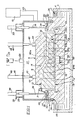
- Figure 1 is a sectioned, side view of a vacuum countergravity casting apparatus in accordance with the invention.
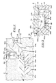
- Figure 2 is a plan view of the upper side of the drag slab along the line 2-2 of Fig. 1 with the runner and pin gate pattern formed in the underside of the mold drag superimposed in phantom lines over the upper side of the drag slab. For clarity, no alloyant is shown in the reaction chamber of the drag slab.
- Figure 3 is an enlarged fragmentary sectioned view taken along line 3-3 of Fig. 2.
- Figure 1 depicts a pool 2 of melt 4 which is to be drawn up into a casting mold assembly 6 comprising a gas-permeable casting mold 7 disposed on a lower drag slab 11 at a parting line 13.
- the casting mold 7 includes a gas permeable upper mold portion 8 (mold cope) and a lower mold portion 10 (mold drag) engaged at a parting line 12 and defining a mold cavity 14 therebetween.
- the melt 4 is contained in an underlying casting furnace or vessel 3 heated by one or more induction coils (not shown) to maintain the melt 4 at a desired casting temperature.
- the drag slab 11 is sealed to the mouth 18 of a vacuum box 20 defining a vacuum chamber 22 via a seal 24 (e.g., high temperature rubber, ceramic rope, etc.).
- the seal 24 is affixed to the lower edge of the depending peripheral side 25 of the vacuum box 20 to this end.
- the vacuum chamber 22 encompasses the upper mold portion 8 and communicates with a vacuum source 23 (e.g., a vacuum pump) via conduit 26.
- the seal 24 on the peripheral wall 25 of the vacuum box 20 may engage the upper mold portion 8 or the lower mold portion 10 in lieu of engaging the drag slab 11.
- the exterior surfaces of the mold 7 and/or drag slab 11 exposed outside the vacuum box 20 may be substantially sealed as by coating with a core wash material (e.g., a silica-slurry) well known in the art to reduce the gas permeability of those surfaces and provide better control of the negative differential pressure established between the inside and the outside of the vacuum box 20.
- a core wash material e.g., a silica-slurry
- one or both of the parting lines 12,13 may be glued to this same end; i.e., to reduce or prevent drawing of air into the mold assembly 6 at the parting lines 12,13.
- the upper mold portion 8 comprises a gas-permeable material (e.g., resin-bonded sand) which permits gases to be withdrawn therethrough from the mold cavity 14 when a vacuum is drawn in the vacuum chamber 22.
- the lower mold portion 10 and the drag slab 11 may conveniently comprise the same material as the upper mold portion 8 or other materials, permeable or impermeable, which are compatible with the material of the upper mold portion 8.
- the drag slab 11 includes an upstanding levee 26 surrounding the seal 24 and isolating it from the melt 4 for purposes described in U.S. Patent 4,745,962 and assigned to the assignee of the present invention.
- the upper and lower mold portions 8,10 and the drag slab 11 are each made in accordance with known mold practice where a compliant (shapeable) mixture of sand or equivalent particles and a settable binder material (e.g., an inorganic or organic thermal or chemical setting plastic resin) is formed to shape and then cured or hardened against respective contoured pattern plates (not shown).
- a compliant (shapeable) mixture of sand or equivalent particles and a settable binder material e.g., an inorganic or organic thermal or chemical setting plastic resin
- the drag slab 11 could be made of a different material resistant to degradation in the melt to enable repeated use in casting multiple disposable molds in succession.
- the drag slab 11 includes a plurality of anchoring sites 28 engaged by T-bar keepers 30 of the type described in commonly assigned U.S. patent application Serial No. 147,863, abandoned in favor of patent application Serial No. 286,051, providing means for mounting a mold assembly to the vacuum box 20.
- the drag slab 11 is provided with a plurality of anchoring cavities 32 adapted to receive the T-bar keepers 30 via slots 34 in the shelves 40 overlying the anchoring cavities 32 and attached to the drag slab 11.
- a 90° rotation of the T-bar carrying shafts 36 e.g., by air motors 38
- Other known mold assembly-to-vacuum box mounting means can also be employed in practicing the invention (e.g., see U.S. Patent 4,658,880).
- the upper mold portion 8, the lower mold portion 10 and the drag slab 11 are pressed into sealing engagement (i.e., at the parting lines 12 and 13) by means of a plurality of plungers 42 so as to eliminate, if desired, the need to glue the upper and lower mold portions 8,10 at the parting line 12 and lower mold portion 10 and drag slab 11 at the parting line 13.
- Feet 44 on the ends of the plungers 42 distribute the force of the plungers 42 more widely across the top of the upper mold portion 8 to prevent penetration/puncture thereof by the ends of the plungers 42.
- Pneumatic springs 46 bias the plungers 42 downwardly to resiliently press the upper mold portion 8 against the lower mold portion 10 and the lower mold portion 10 against the drag slab 11 as the mold assembly 6 is being positioned in the mouth 18 of the vacuum box 22.
- Schrader valves 48 on the air springs 46 permit varying the pressure in the springs 46 as needed to apply sufficient force to press the upper mold portion 8, the lower mold portion 10 and the drag slab 11 into sealing engagement, and, as needed, to prevent destructive inward flexure of the mold assembly 6 when the casting vacuum is drawn.
- the force applied by the plungers 42 will not be so great as to overpower and damage the anchoring sites 28, dislodge the mold assembly 6 from the mouth 18 of the box 20, or break the seal formed thereat.
- the drag slab 11 includes a single sprue 50 having a lower inlet 50a for engaging the pool 2 and supplying the melt 4 to a reaction chamber 52 when the lower side 11a of the drag slab 11 is immersed in the pool 2 with the mold cavity 14 evacuated.
- the sprue 50 extends between the lower side 11a and the upper side 11b of the drag slab 11 and is in flow communication with the reaction chamber 52 via a recessed inlet chamber 54 formed in the upper side 11b of the drag slab 11.
- the reaction chamber 52 includes a horizontal bottom wall 52a and upstanding (slightly outwardly diverging) side walls 52b.
- the top of the reaction chamber 52 and the recessed inlet chamber 54 are closed off by the bottom side 7a of the casting mold 7 (i.e., by the bottom side of the mold drag 10) as best shown in Fig. 3.
- an alloyant 60 in suitable form (e.g., alloy particulate) is disposed in the reaction chamber 52 to be so contacted by the melt 4 drawn upwardly through the sprue 50 and into the reaction chamber 52 during countergravity casting as to introduce a selected quantity of the alloyant 60 into the melt 4 immediately prior to its entering the mold cavity 14.
- the alloyant 60 is positioned in the reaction chamber 52 of the drag slab 11 before the drag slab 11 is assembled with the casting mold 7.
- the appropriate quantity of the alloyant 60 is first placed in the reaction chamber 52 of the drag slab 11 and the casting mold 7 is then disposed atop the drag slab 11 as shown in Fig. 1.
- the mold 7 is described as including a single mold cavity 14, the invention envisions supplying the treated melt 4 from the reaction chamber 52 to a plurality of mold cavities 14 in one or more molds 7 disposed on the drag slab 11.
- the reaction chamber 52 includes an inlet 52c at its juncture with the recessed inlet chamber 54 and an outlet 52d at its juncture with a primary, lateral (horizontal) runner 62 formed in the bottom side 7a of the mold 7.
- the runner 62 communicates in flow relation with a secondary lateral (horizontal) runner 64 also formed in the bottom side 7a of the mold 7.
- the secondary runner 64 in turn communicates in flow relation with each of the plurality of narrow upstanding ingates 16 (i.e., pin gates) formed in the lower mold portion 10 and extending between the mold cavity 14 and the bottom side 7a.
- the primary runner 62 includes a riser portion 62a proximate the outlet 52d of the reaction chamber 52.
- the riser portion 62a has an increased vertical dimension (compared to other portions 62b of the runner 62 remote from the reaction chamber outlet 52d) so as to trap dross inclusions and other floating debris in the treated melt 4 exiting the reaction chamber 52.
- the outlet 52d of the reaction chamber 52 communicates directly with the riser portion 62a formed in the bottom side 7a of the mold 7 to this end.
- the secondary runner includes a main runner portion 64a and a plurality of branch runner portions 64b each communicating with a respective ingate 16.
- the ingates 16 pin gates
- the ingates 16 preferably have a major dimension (e.g., diameter for the cylindrical ingates shown) not exceeding about 0.50 inch, preferably not exceeding about 0.25 inch (e.g., about .22 inch) for purposes set forth in U.S. Patent 4,340,108 and hereinafter described.
- a particular pattern of the primary and secondary runners 62,64 formed in the bottom side 7a of the mold 7 is shown best in Fig. 2 wherein the pattern is superimposed in phantom lines atop the upper side 11b of the drag slab 11.
- countergravity casting of the melt 4 into the casting mold assembly 6 is effected by relatively moving the mold assembly 6 and the pool 2 to immerse the underside 11a of the drag slab 11 in the melt 4.
- the casting mold assembly 6 is lowered toward the pool 2 using a hydraulic power cylinder 61 (shown schematically) actuating a movable support arm 63 (shown schematically) that is connected to the vacuum box 20.
- the vacuum chamber 22 is then evacuated to draw the melt 4 upwardly through the sprue 50 and through reaction chamber 52 where the melt 4 so contacts the alloyant 60 as to have the alloyant 60 introduced (e.g., dissolved) therein above a predetermined effective concentration.
- the treated melt 4 i.e., the melt containing the alloyant
- the vacuum box 22 is raised by hydraulic power cylinder 60 to withdraw the underside 11a of the drag slab 11 out of the pool 2.
- the number and size of the narrow pin gates 16 to achieve melt solidification initially at the pin gates 16 can be selected in accordance with the teachings of U.S. Patent 4,340,108.
- the treated melt 4 can be allowed to solidify in both the pin gates 16 and the mold cavity 14 before raising the vacuum box 22 to withdraw the mold assembly 6 out of the pool 2. The vacuum box 22 and the melt-filled mold assembly 6 are then separated.
- the size and shape of the sprue 50, reaction chamber 52 and inlet chamber 54 formed in the drag slab 11 are dependent upon the size and shape of the part to be cast as well as on the composition of the specific melt 4 and alloyant 60 employed. Moreover, the size and shape of the primary and secondary runners 62,64 and pin gates 16 formed in the mold drag 10 are similarly dependent. These features of the mold assembly 6 are selected to provide a desired melt flow rate and residence time in the reaction chamber 52 and melt flow rate into the mold cavity 12.
- a casting mold 7 and drag slab 11 similar to those described hereinabove were used to countergravity cast an automobile engine manifold of nodular iron.
- the cast exhaust manifold weighed about 21 lbs. including the solidified metal in the reaction chamber 52, runners 62,64 and pin gates 16.
- the reaction chamber 52 included an upper square (about 4.47 inch x about 4.47 inch) cross-section tapering down (5 ) to a depth of about 2.52 inches to provide a lower square (about 4.05 inch x about 4.05 inch) cross-section at the bottom wall 52a.
- the sprue 50 had a length of about 3.70 inches and a maximum diameter of about 1.40 inch at its outlet adjacent the recessed inlet chamber 54 and minimum diameter of about .79 inch at its inlet 50a.
- the recessed chamber 54 was about .30 inch in depth and about 1.62 inch in width where it intersected the reaction chamber 52 to provide a reaction chamber inlet area of about .49 square inches.
- the longitudinal axis of the sprue 50 was offset from the reaction chamber inlet 52c by about 1.25 inch.
- the primary and secondary runners 62,64 were formed in the bottom side 7a of the casting mold 7 in a pattern similar to that illustrated in Fig. 2.
- the primary runner 62 had an overall length of about 5.12 inches.
- the riser portion 62a of the primary runner 62 was rectangular in cross-section (about 1.68 inch major width x about .413 minor width x about 1.00 inch height) and intersected the reaction chamber 52 to provide a reaction chamber outlet area of about .42 square inches.
- the area of the reaction chamber outlet 52d was selected to maintain the reaction chamber 52 metalloscatically pressurized and filled with the melt 4 during the entire casting process (i.e., until the mold cavity 14 was filled with the melt 4).
- the smaller potions 62b of the primary runner 62 had a square cross-section (about .413 inch x about .413 inch).
- the main portion 64a of the secondary runners 64 had a square cross-section (about .413 inch x about .413 inch) and an overall length of about 25.62 inches (the left hand segment in Fig. 2 being about 14.50 inches in length and the right hand segment being about 11.12 inches in length).
- the smaller branch portions 64b of the secondary runners 64 each had a generally square cross-section (about .220 inch x about .220 inch).
- the branch portions 64b were formed with cylindrical wells 64c (about .375 inch diameter) in communication with each cylindrical pin gate 16 (.220 inch diameter) formed in the mold drag 10.
- a total of fifteen pin gates 16 were used to supply treated molten iron to the manifold-shaped mold cavity 14.
- Molten metal Filter (not shown) may be used in the runner system 62,64
- an inoculant alloy 60 in particulate form Prior to assembly of the casting mold 7 and the drag slab 11, about 120 grams (0.264 lbs.) of an inoculant alloy 60 in particulate form (e.g., 5 x 18 mesh) was positioned in the reaction chamber 52 to a depth of about .25 inches.
- the inoculant alloy 60 has a nominal composition in weight percent (w/o) of 4.06 w/o Mg, 46.04 w/o Si, 1.14 w/o total rare earths, .48 w/o Ca, .71 w/o Al, balance Fe and is available under the trademark INMOLD II inoculant alloy owned by Material & Methods Limited, surrey, England.
- a gray iron melt 4 devoid of any carbon nodularizing agent was maintained at about 2640°F in the underlying casting vessel 3.
- the melt 4 was drawn upwardly from the vessel 3 by establishing a suitable vacuum in the vacuum chamber 22 (e.g., about 140 inches of water) when the lower side 11a of the drag slab 11 was immersed in the melt 4.
- the iron melt 4 was drawn upwardly through the sprue 50 and passed through the reaction chamber 52 where it reacted (dissolved) the INMOLD II inoculant alloy 60.
- the treated iron melt 4 was supplied to the mold cavity 14 via the runners 62,64 and the pin gates 16.
- the solidified exhaust manifold casting was sectioned, examined and found to contain nodularizied carbon (graphite) throughout the casting.
- alloyants such as copper, chromium, manganese, molybdenum, silicon as well as others that are soluble in the melt 4 may be introduced into the melt 4 during countergravity casting in accordance with the invention.
- the alloyant 60 in the reaction chamber 52 may comprise copper in particulate or other form.
- a ferritic nodular iron melt 4 (corresponding in composition to the known ferritic nodular iron grade 4010) is drawn upwardly from the casting vessel 3 through the sprue 50, through the reaction chamber 52 and then into the mold cavity 14 in the manner as described hereinabove.
- the copper is introduced (i.e., dissolved) into the melt 4 as it passes through the reaction chamber 52 in a sufficient amount (e.g., about 0.4 w/o minimum to about .5 w/o maximum) to impart a microstructure and mechanical properties to the resultant casting corresponding to the known pearlitic nodular iron grade 5203.
- the present invention thus envisions producing castings having different compositions/microstructures and resultant mechanical properties from a common underlying melt 4 by successively countergravity casting a plurality of mold assemblies 6 having different alloyants 60 in their reaction chambers 52 from the common pool 2.
- a "universal" cupola melt thus can be used to supply the common pool 2.
- the need to prepare and handle different base melts in one or more melting vessels/ladles is thereby eliminated.
- the flexibility of the vacuum countergravity casting process in meeting ever changing production schedule variations is tremendously improved.
- the invention is not limited to the casting of cast irons and may also be used in the differential pressure, countergravity casting of other metal/alloys where selective introduction of one or more alloyants is desired for some purpose.
- the present invention may be used to introduce (dissolve) known degassing, desulfurizing, deslagging and similar treating agents into aluminum and steel during the vacuum countergravity casting thereof.
Landscapes
- Engineering & Computer Science (AREA)
- Mechanical Engineering (AREA)
- Molds, Cores, And Manufacturing Methods Thereof (AREA)
Applications Claiming Priority (2)
| Application Number | Priority Date | Filing Date | Title |
|---|---|---|---|
| US485587 | 1990-02-27 | ||
| US07/485,587 US5038846A (en) | 1990-02-27 | 1990-02-27 | Differential pressure, countergravity casting with alloyant reaction chamber |
Publications (2)
| Publication Number | Publication Date |
|---|---|
| EP0444320A2 true EP0444320A2 (de) | 1991-09-04 |
| EP0444320A3 EP0444320A3 (en) | 1993-08-25 |
Family
ID=23928710
Family Applications (1)
| Application Number | Title | Priority Date | Filing Date |
|---|---|---|---|
| EP19900125797 Withdrawn EP0444320A3 (en) | 1990-02-27 | 1990-12-28 | Differential pressure countergravity casting with alloyant reaction chamber |
Country Status (5)
| Country | Link |
|---|---|
| US (1) | US5038846A (de) |
| EP (1) | EP0444320A3 (de) |
| JP (1) | JPH04220154A (de) |
| BR (1) | BR9100246A (de) |
| CA (1) | CA2030495A1 (de) |
Cited By (1)
| Publication number | Priority date | Publication date | Assignee | Title |
|---|---|---|---|---|
| EP0562170A1 (de) * | 1992-03-26 | 1993-09-29 | General Motors Corporation | Differentialdruck-Gegenschwerkraftgiessen |
Families Citing this family (6)
| Publication number | Priority date | Publication date | Assignee | Title |
|---|---|---|---|---|
| US5174356A (en) * | 1991-07-19 | 1992-12-29 | General Motors Corporation | Casting apparatus |
| US5887646A (en) * | 1997-01-16 | 1999-03-30 | Ford Global Technologies, Inc. | Modular sand mold system for metal treatment and casting |
| DE112006000461T5 (de) | 2005-02-22 | 2008-03-13 | Milwaukee School Of Engineering, Milwaukee | Gießverfahren |
| WO2012092244A2 (en) | 2010-12-29 | 2012-07-05 | Android Industries Llc | Working tank with vacuum assist |
| US8770265B2 (en) | 2011-12-28 | 2014-07-08 | Bedloe Industries Llc | Method and system for manufacturing railcar couplers |
| EP3544716A4 (de) | 2017-10-27 | 2020-06-24 | United Technologies Corporation | Vorrichtung zum steigenden giessen und entschwefelungsverfahren |
Family Cites Families (25)
| Publication number | Priority date | Publication date | Assignee | Title |
|---|---|---|---|---|
| US3488756A (en) * | 1967-01-09 | 1970-01-06 | Potter Instrument Co Inc | Speed control system for a low inertia d.c. motor |
| US3414250A (en) * | 1967-07-31 | 1968-12-03 | American Cast Iron Pipe Co | Ladle for use in treatment of molten metal |
| GB1278265A (en) * | 1968-07-17 | 1972-06-21 | Materials & Methods Ltd | Improved process for the manufacture of nodular cast iron |
| GB1311093A (en) * | 1969-03-13 | 1973-03-21 | Materials & Methods Ltd | Process for the treatment of molten metals |
| GB1511246A (en) * | 1974-04-29 | 1978-05-17 | Materials & Methods Ltd | Process for the manufacture of cast iron |
| US3746078A (en) * | 1971-02-04 | 1973-07-17 | Meehanite Metal Corp | Gating system for introducing additives to molten metal |
| US3765876A (en) * | 1972-11-01 | 1973-10-16 | W Moore | Method of making nodular iron castings |
| US3900064A (en) * | 1972-12-04 | 1975-08-19 | Hitchiner Manufacturing Co | Metal casting |
| US3870512A (en) * | 1973-03-05 | 1975-03-11 | Deere & Co | Method of producing spheroidal graphite cast iron |
| FR2226233B1 (de) * | 1973-04-20 | 1976-11-12 | Renault | |
| GB1472321A (en) * | 1973-05-28 | 1977-05-04 | Pont A Mousson | Substance for nodularizing graphite in liquid cast iron and a process for using said substance |
| US4125144A (en) * | 1973-11-08 | 1978-11-14 | Toyota Jidosha Kogyo Kabushiki Kaisha | Refractory material for labeling, which contains an activatable element |
| US4037643A (en) * | 1975-08-22 | 1977-07-26 | Ford Motor Company | Nodularizing treatment employing unitized modifying agent |
| US4040821A (en) * | 1975-08-22 | 1977-08-09 | Ford Motor Company | Nodularizing catalyst for cast iron and method of making same |
| US4606396A (en) * | 1978-10-02 | 1986-08-19 | Hitchiner Manufacturing Co., Inc. | Sand mold and apparatus for reduced pressure casting |
| JPS5550965A (en) * | 1978-10-09 | 1980-04-14 | Mitsubishi Heavy Ind Ltd | Production of spherical graphite castings |
| US4210195A (en) * | 1978-12-13 | 1980-07-01 | Ford Motor Company | Method of treating cast iron using packaged granular molten metal treatment mold inserts |
| US4340108A (en) * | 1979-09-12 | 1982-07-20 | Hitchiner Manufacturing Co., Inc. | Method of casting metal in sand mold using reduced pressure |
| JPS56111551A (en) * | 1980-02-08 | 1981-09-03 | Takaoka Kogyo Kk | Installation method for graphite spheroidizing agent in mold |
| US4312688A (en) * | 1980-02-11 | 1982-01-26 | Brodis Eric P | Method and apparatus for making simulated stained-glass |
| US4638846A (en) * | 1980-07-01 | 1987-01-27 | Ford Motor Company | Method of making thin-walled ductile iron castings |
| US4330024A (en) * | 1980-08-27 | 1982-05-18 | Steel Founder's Society Of America | Method for in-mold deoxidation of steel |
| JPS59150654A (ja) * | 1983-02-18 | 1984-08-28 | Hitachi Metals Ltd | 減圧鋳造法における接種方法 |
| JPS60196259A (ja) * | 1984-03-15 | 1985-10-04 | Takaoka Kogyo Kk | 溶融金属への添加材添加方法 |
| US4865113A (en) * | 1988-08-30 | 1989-09-12 | General Motors Corporation | Countergravity casting apparatus and process for casting thin-walled parts |
-
1990
- 1990-02-27 US US07/485,587 patent/US5038846A/en not_active Expired - Fee Related
- 1990-11-21 CA CA002030495A patent/CA2030495A1/en not_active Abandoned
- 1990-12-28 EP EP19900125797 patent/EP0444320A3/en not_active Withdrawn
-
1991
- 1991-01-21 BR BR919100246A patent/BR9100246A/pt not_active Application Discontinuation
- 1991-02-26 JP JP3053135A patent/JPH04220154A/ja not_active Withdrawn
Cited By (1)
| Publication number | Priority date | Publication date | Assignee | Title |
|---|---|---|---|---|
| EP0562170A1 (de) * | 1992-03-26 | 1993-09-29 | General Motors Corporation | Differentialdruck-Gegenschwerkraftgiessen |
Also Published As
| Publication number | Publication date |
|---|---|
| US5038846A (en) | 1991-08-13 |
| EP0444320A3 (en) | 1993-08-25 |
| CA2030495A1 (en) | 1991-08-28 |
| JPH04220154A (ja) | 1992-08-11 |
| BR9100246A (pt) | 1991-10-22 |
Similar Documents
| Publication | Publication Date | Title |
|---|---|---|
| US4961455A (en) | Countergravity casing apparatus and method with magnetically actuated valve to prevent molten metal run-out | |
| CA1239010A (en) | Metal casting | |
| US4993473A (en) | Differential pressure, countergravity casting using mold ingate chills | |
| US5038846A (en) | Differential pressure, countergravity casting with alloyant reaction chamber | |
| US4862945A (en) | Vacuum countergravity casting apparatus and method with backflow valve | |
| US5271451A (en) | Metal casting using a mold having attached risers | |
| US4901781A (en) | Method of casting a metal matrix composite | |
| KR890004167B1 (ko) | 저압주조의 용융금속 접종방법과 장치 | |
| EP0473062A2 (de) | Differentialdruck-Gegenschwerkraftgiessen mit Einführung einer Legierung in die Schmelze | |
| EP0562170B1 (de) | Differentialdruck-Gegenschwerkraftgiessen | |
| GB1559584A (en) | Method and apparatus for conditioning molten cast iron | |
| US4989662A (en) | Differential pressure, countergravity casting of a melt with a fugative alloyant | |
| US5390723A (en) | Method of treating casting metals | |
| EP0415091B1 (de) | Gegenschwerkraftgiessen unter Benutzung von gesondert gefüllten Vakuumkammern | |
| EP0078611B1 (de) | Behandlung von Gussmetall im Formkastenoberteil-Giessbecken | |
| EP0444319A2 (de) | Wirkdruck beim Gegen-Schwerkraft-Giessen mit selektiver Einführung der Legierung | |
| US4779663A (en) | Process and apparatus for producing ductile iron castings | |
| CA1078132A (en) | Method of making ductile iron treating agents | |
| US4977946A (en) | Differential pressure, countergravity casting of individual charges of melt from a casting basin | |
| US4723763A (en) | Device for continuous injection under low pressure of a powdered additive into a stream of molten metal | |
| US5062467A (en) | Vacuum countergravity casting apparatus and method | |
| JPS6434571A (en) | Full mold casting method | |
| SU959892A1 (ru) | Способ поверхностного упрочнени металлических литейных форм | |
| Rooze et al. | Manufacture of Cast-Iron Ingot Molds | |
| JP2000005864A (ja) | 溶湯の接種方法及びその装置 |
Legal Events
| Date | Code | Title | Description |
|---|---|---|---|
| PUAI | Public reference made under article 153(3) epc to a published international application that has entered the european phase |
Free format text: ORIGINAL CODE: 0009012 |
|
| AK | Designated contracting states |
Kind code of ref document: A2 Designated state(s): DE FR GB IT |
|
| PUAL | Search report despatched |
Free format text: ORIGINAL CODE: 0009013 |
|
| AK | Designated contracting states |
Kind code of ref document: A3 Designated state(s): DE FR GB IT |
|
| STAA | Information on the status of an ep patent application or granted ep patent |
Free format text: STATUS: THE APPLICATION HAS BEEN WITHDRAWN |
|
| 18W | Application withdrawn |
Withdrawal date: 19940218 |