EP0443907B1 - Method for automatically setting paper in the paper cutter of a printing machine - Google Patents
Method for automatically setting paper in the paper cutter of a printing machine Download PDFInfo
- Publication number
- EP0443907B1 EP0443907B1 EP91400340A EP91400340A EP0443907B1 EP 0443907 B1 EP0443907 B1 EP 0443907B1 EP 91400340 A EP91400340 A EP 91400340A EP 91400340 A EP91400340 A EP 91400340A EP 0443907 B1 EP0443907 B1 EP 0443907B1
- Authority
- EP
- European Patent Office
- Prior art keywords
- paper
- cover
- roll
- opening
- free end
- Prior art date
- Legal status (The legal status is an assumption and is not a legal conclusion. Google has not performed a legal analysis and makes no representation as to the accuracy of the status listed.)
- Expired - Lifetime
Links
- 238000000034 method Methods 0.000 title claims description 12
- 238000011144 upstream manufacturing Methods 0.000 claims description 4
- 230000000717 retained effect Effects 0.000 claims description 3
- 238000010276 construction Methods 0.000 description 1
- 230000002950 deficient Effects 0.000 description 1
Images
Classifications
-
- B—PERFORMING OPERATIONS; TRANSPORTING
- B41—PRINTING; LINING MACHINES; TYPEWRITERS; STAMPS
- B41J—TYPEWRITERS; SELECTIVE PRINTING MECHANISMS, i.e. MECHANISMS PRINTING OTHERWISE THAN FROM A FORME; CORRECTION OF TYPOGRAPHICAL ERRORS
- B41J15/00—Devices or arrangements of selective printing mechanisms, e.g. ink-jet printers or thermal printers, specially adapted for supporting or handling copy material in continuous form, e.g. webs
- B41J15/04—Supporting, feeding, or guiding devices; Mountings for web rolls or spindles
- B41J15/042—Supporting, feeding, or guiding devices; Mountings for web rolls or spindles for loading rolled-up continuous copy material into printers, e.g. for replacing a used-up paper roll; Point-of-sale printers with openable casings allowing access to the rolled-up continuous copy material
-
- B—PERFORMING OPERATIONS; TRANSPORTING
- B41—PRINTING; LINING MACHINES; TYPEWRITERS; STAMPS
- B41J—TYPEWRITERS; SELECTIVE PRINTING MECHANISMS, i.e. MECHANISMS PRINTING OTHERWISE THAN FROM A FORME; CORRECTION OF TYPOGRAPHICAL ERRORS
- B41J11/00—Devices or arrangements of selective printing mechanisms, e.g. ink-jet printers or thermal printers, for supporting or handling copy material in sheet or web form
- B41J11/66—Applications of cutting devices
- B41J11/70—Applications of cutting devices cutting perpendicular to the direction of paper feed
Definitions
- the subject of the present invention is a process for automatically placing paper in the paper cutter of a printing machine of the type comprising, upstream of the paper cutter, a paper feed roll, a printing roll and a head. printing cooperating with the printing roller and carried by a pivoting cover closing an opening formed in the upper wall of the machine and giving access to the food roller and the printing roller when the cover is raised.
- the present invention therefore aims to remedy the drawbacks of the method defined above.
- the present invention relates to a process for automatically placing paper in the paper cutter of a printing machine, of the type comprising, upstream of the paper cutter, a paper feed roll, a print roll and a printhead cooperating with the printing roller and carried by a pivoting cover closing an opening in the upper wall of the machine and giving access to the food roller and the printing roller when the cover is raised, process in which, after opening the cover swivel and place the paper food roll in its housing, unroll the paper from the roll, close the cover, thus retaining the paper at the outlet of the printing roller, start the machine in the direction of rewinding the paper to bring the end of the tape to the downstream outlet of the printing roller, then restart the machine in the direction of unwinding of the paper to push the tape up u that its cut free end enters the paper cutter, characterized in that, before closing the cover, the paper is rolled out from the roll until part of it comes out through the upper wall opening and , after having closed the cover, the paper being retained between the free end edge of the
- the process of the invention ensures automatic positioning of the paper in the paper cutter, manual intervention being limited, apart from the laying of the paper food roll in its housing, when cutting a portion of strip on the free end edge of the cover. Because of this strip end cut, we are assured of the perfect condition of this end, obviously facilitating its introduction into the paper cutter.
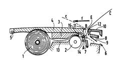
- a printing machine such as for example a fax machine, namely the paper food roll 1, the printing roll 2, cooperating with a print head 3 carried by a pivoting cover 4 around the axis 5, the paper cutter 6 comprising a lower pivoting blade 7 and an upper pivoting blade 8 provided with flexible blades 9.
- the cover 4 closes an opening formed in the upper wall 10 of the machine, and its free end edge 11 faces the corresponding edge 12 of this opening, thus delimiting a gap E allowing the passage of the paper.
- the guide element On either side of the printing roller 2, elements for guiding the paper strip C are provided. Between the paper roller 1 and the printing roller 2, the guide element is constituted by a chute 13 which faces at the print head 3 and, on the other side of the roller 2, the guide element is formed by a plate 14 and a stud 15 carried by the cover 4.
- the roll of paper 1 is introduced through the upper opening and placed in its housing. Pull on the strip C, which passes over the chute 13 and the printing roller 2, to get it out of the upper opening of an arbitrary length, for example 20 cm.
- the cover 4 is closed and the print head 3 applies the paper strip in its guide chute 13 and against the printing roller 2.
- the stud 15 retains at A, against the plate 14, the strip which is retained also between the edge 11 of the cover 4 and the edge 12 of the upper opening.
- the strip is then pulled by its end in the direction of arrow F to produce its cut at B against the edge 11 of the cover 4.
- the distance l between the points A and B is determined by construction.
- the machine is then rotated in the direction of rewinding the paper on its roll, so as to swallow up the strip section of length l .
Landscapes
- Handling Of Sheets (AREA)
- Rotary Presses (AREA)
Abstract
Description
La présente invention a pour objet un procédé de mise en place automatique du papier dans le coupe-papier d'une machine imprimante du type comportant, en amont du coupe-papier, un rouleau alimentaire de papier, un rouleau imprimeur et une tête d'impression coopérant avec le rouleau imprimeur et portée par un capot pivotant obturant une ouverture ménagée dans la paroi supérieure de la machine et donnant accès au rouleau alimentaire et au rouleau imprimeur lorsque le capot est soulevé.The subject of the present invention is a process for automatically placing paper in the paper cutter of a printing machine of the type comprising, upstream of the paper cutter, a paper feed roll, a printing roll and a head. printing cooperating with the printing roller and carried by a pivoting cover closing an opening formed in the upper wall of the machine and giving access to the food roller and the printing roller when the cover is raised.
La mise en place manuelle du papier dans le coupe-papier de ce type de machines est une opération délicate, qui prend souvent plus de temps que prévu et dont le résultat est parfois défectueux, du fait notamment du mauvais état de l'extrémité de la bande de papier que l'on doit introduire dans le coupe-papier.The manual placement of the paper in the paper cutter of this type of machine is a delicate operation, which often takes longer than expected and the result of which is sometimes defective, due in particular to the poor condition of the end of the strip of paper to be inserted into the cutter.
On connaît déjà par le document PATENT ABSTRACTS OF JAPAN, vol.11, no.302 (M-629) (2749), 2 octobre 1987 ; & JP-A-6293176 (RICOH) 28.04.1987 un procédé similaire à celui défini en objet. Mais il n'y est pas enseigné de découper la bande de papier contre le capot ni surtout de résoudre le problème du mauvais état de l'extrémité de la bande de papier.We already know from the document PATENT ABSTRACTS OF JAPAN, vol.11, no.302 (M-629) (2749), October 2, 1987; & JP-A-6293176 (RICOH) 28.04.1987 a process similar to that defined in object. But it is not taught there to cut the paper strip against the cover nor especially to solve the problem of the bad condition of the end of the paper strip.
On connaît encore par le document PATENT ABSTRACTS OF JAPAN, vol.12, no.269 (M-723) (3116), 27 juillet 1988 ; JP-A-6351252 (CANON) 04.03.1988 un procédé enseignant de découper, en amont d'une tête, une bande de papier, mais, non pas pour pallier le mauvais état de l'extrémité d'une bande de papier, mais pour éviter son entraînement par une autre feuille.We also know from the document PATENT ABSTRACTS OF JAPAN, vol.12, no.269 (M-723) (3116), July 27, 1988; JP-A-6351252 (CANON) 04.03.1988 a teaching method of cutting, upstream of a head, a strip of paper, but, not to alleviate the bad state of the end of a strip of paper, but to avoid its entrainment by another sheet.
La présente invention vise donc à remédier aux inconvénients du procédé défini ci-dessus.The present invention therefore aims to remedy the drawbacks of the method defined above.
A cet effet, la présente invention concerne un procédé de mise en place automatique du papier dans le coupe-papier d'une machine imprimante, du type comportant, en amont du coupe-papier, un rouleau alimentaire de papier, un rouleau imprimeur et une tête d'impression coopérant avec le rouleau imprimeur et portée par un capot pivotant obturant une ouverture ménagée dans la paroi supérieure de la machine et donnant accès au rouleau alimentaire et au rouleau imprimeur lorsque le capot est soulevé, procédé dans lequel, après ouverture du capot pivotant et mise en place du rouleau alimentaire de papier dans son logement, on déroule le papier du rouleau, on referme le capot , retenant ainsi le papier à la sortie du rouleau imprimeur, on met en marche la machine dans le sens du réenroulement du papier pour ramener l'extrémité de bande à la sortie aval du rouleau imprimeur, puis on remet en marche la machine dans le sens de déroulement du papier pour repousser la bande jusqu'à ce que son extrémité libre découpée pénètre dans le coupe-papier, caractérisé par le fait que, avant de refermer le capot, on déroule le papier du rouleau jusqu'à en faire sortir une partie par l'ouverture de paroi supérieure et, après avoir refermé le capot, le papier étant retenu entre le bord d'extrémité libre du capot et le bord d'ouverture opposé, on tire la partie de papier sortie de l'ouverture pour la rabattre contre le capot et provoquer sa découpure contre son bord d'extrémité libre.To this end, the present invention relates to a process for automatically placing paper in the paper cutter of a printing machine, of the type comprising, upstream of the paper cutter, a paper feed roll, a print roll and a printhead cooperating with the printing roller and carried by a pivoting cover closing an opening in the upper wall of the machine and giving access to the food roller and the printing roller when the cover is raised, process in which, after opening the cover swivel and place the paper food roll in its housing, unroll the paper from the roll, close the cover, thus retaining the paper at the outlet of the printing roller, start the machine in the direction of rewinding the paper to bring the end of the tape to the downstream outlet of the printing roller, then restart the machine in the direction of unwinding of the paper to push the tape up u that its cut free end enters the paper cutter, characterized in that, before closing the cover, the paper is rolled out from the roll until part of it comes out through the upper wall opening and , after having closed the cover, the paper being retained between the free end edge of the cover and the opposite opening edge, the portion of paper taken out of the opening is pulled to fold it against the cover and cause it to be cut against its free end edge.
On voit que le procédé de l'invention assure une mise en place automatique du papier dans le coupe-papier, l'intervention manuelle étant limitée, en dehors de la pose du rouleau alimentaire de papier dans son logement, à la coupe d'une portion de bande sur le bord d'extrémité libre du capot. Du fait de cette coupe d'extrémité de bande, on est assuré du parfait état de cette extrémité, facilitant évidemment son introduction dans le coupe-papier.It can be seen that the process of the invention ensures automatic positioning of the paper in the paper cutter, manual intervention being limited, apart from the laying of the paper food roll in its housing, when cutting a portion of strip on the free end edge of the cover. Because of this strip end cut, we are assured of the perfect condition of this end, obviously facilitating its introduction into the paper cutter.
Le procédé de l'invention est illustré par la figure unique du dessin annexé, pour l'expliquer de façon plus détaillée, mais nullement limitative.The process of the invention is illustrated by the single figure of the appended drawing, to explain it in more detail, but in no way limiting.
Sur cette figure, sont représentés schématiquement les éléments principaux d'une machine imprimante, comme par exemple un télécopieur, à savoir le rouleau alimentaire de papier 1, le rouleau imprimeur 2, coopérant avec une tête d'impression 3 portée par un capot 4 pivotant autour de l'axe 5, le coupe-papier 6 comportant une lame pivotante inférieure 7 et une lame pivotante supérieure 8 munie de lames souples 9.In this figure, are schematically represented the main elements of a printing machine, such as for example a fax machine, namely the paper food roll 1, the
Le capot 4 obture une ouverture ménagée dans la paroi supérieure 10 de la machine, et son bord d'extrémité libre 11 fait face au bord correspondant 12 de cette ouverture, délimitant ainsi un interstice E permettant le passage du papier.The cover 4 closes an opening formed in the
De part et d'autre du rouleau imprimeur 2, sont prévus des éléments de guidage de la bande de papier C. Entre le rouleau de papier 1 et le rouleau imprimeur 2, l'élément de guidage est constitué par une goulotte 13 qui fait face à la tête d'impression 3 et, de l'autre côté du rouleau 2, l'élément de guidage est formé par une plaque 14 et un téton 15 porté par le capot 4.On either side of the
Dans la machine agencée comme elle vient d'être décrite, on comprend qu'en procédant selon l'invention, le papier sera mis en place automatiquement dans le coupe-papier 6.In the machine arranged as just described, it is understood that by proceeding according to the invention, the paper will be placed automatically in the
Le procédé de l'invention est maintenant expliqué en détail, en se référant à la figure schématique annexée.The process of the invention is now explained in detail, with reference to the attached schematic figure.
Le capot 4 étant soulevé, on introduit par l'ouverture supérieure, le rouleau de papier 1 qu'on met dans son logement. On tire sur la bande C, qui passe au-dessus de la goulotte 13 et du rouleau imprimeur 2, pour la faire sortir de l'ouverture supérieure d'une longueur arbitraire, par exemple 20 cm. On ferme le capot 4 et la tête d'impression 3 applique la bande de papier dans sa goulotte de guidage 13 et contre le rouleau imprimeur 2. Par ailleurs, le téton 15 retient en A, contre la plaque 14, la bande qui est retenue également entre le bord 11 du capot 4 et le bord 12 de l'ouverture supérieure.With the cover 4 raised, the roll of paper 1 is introduced through the upper opening and placed in its housing. Pull on the strip C, which passes over the
On tire ensuite la bande par son extrémité dans la direction de la flèche F pour produire sa coupure en B contre le bord 11 du capot 4. La distance l entre les pointes A et B est déterminée par construction.The strip is then pulled by its end in the direction of arrow F to produce its cut at B against the edge 11 of the cover 4. The distance l between the points A and B is determined by construction.
On fait alors tourner la machine dans le sens du rembobinage du papier sur son rouleau, de façon à ravaler la section de bande de longueur l.The machine is then rotated in the direction of rewinding the paper on its roll, so as to swallow up the strip section of length l .
Il suffit ensuite de refaire tourner le rouleau 2 dans le sens du déroulement pour repousser cette section de bande, dont l'extrémité est parfaitement coupée, vers le coupe-papier 6, dans la zone D comprise entre les lames 9 et l'élément inférieur 7.Then simply turn the
Claims (1)
- Method of automatically putting paper in the paper cutter of a printing machine, of the type including, upstream of the paper cutter, a paper feed roll, a printer roll and a printing head interacting with the printer roll and carried by a pivoting cover closing off an opening made in the upper wall of the machine and giving access to the feed roll and to the printer roll when the cover is raised, in which method, after opening the pivoting cover (4) and putting the paper feed roll (1) in place in its housing, the paper is unwound from the roll (1), the cover (4) is closed again, thus retaining the paper at the output of the printer roll, the machine is switched on in the direction of rewinding of the paper in order to bring the end of the web to the downstream output of the printer roll (2) and then the machine is switched on again in the direction of unwinding of the paper in order to drive the web until its cut free end penetrates the paper cutter (6), characterized in that, before closing the cover (4) again, the paper is unwound from the roll (1) until a portion of it has been taken out through the opening in the upper wall (10) and, after having closed the cover (4) again, the paper being retained between the free end edge (11) of the cover and the opposite end (12) of the opening, the portion of paper taken out through the opening is pulled in order to bring it back down against the cover (4) and to cause it to be cut against its free end edge (11).
Applications Claiming Priority (2)
| Application Number | Priority Date | Filing Date | Title |
|---|---|---|---|
| FR9002009 | 1990-02-20 | ||
| FR9002009A FR2658447B1 (en) | 1990-02-20 | 1990-02-20 | PROCESS FOR AUTOMATICALLY PLACING PAPER IN THE PAPER CUTTER OF A PRINTER MACHINE. |
Publications (2)
| Publication Number | Publication Date |
|---|---|
| EP0443907A1 EP0443907A1 (en) | 1991-08-28 |
| EP0443907B1 true EP0443907B1 (en) | 1996-09-11 |
Family
ID=9393898
Family Applications (1)
| Application Number | Title | Priority Date | Filing Date |
|---|---|---|---|
| EP91400340A Expired - Lifetime EP0443907B1 (en) | 1990-02-20 | 1991-02-12 | Method for automatically setting paper in the paper cutter of a printing machine |
Country Status (4)
| Country | Link |
|---|---|
| EP (1) | EP0443907B1 (en) |
| AT (1) | ATE142564T1 (en) |
| DE (1) | DE69121938D1 (en) |
| FR (1) | FR2658447B1 (en) |
Families Citing this family (2)
| Publication number | Priority date | Publication date | Assignee | Title |
|---|---|---|---|---|
| DE69511762T2 (en) * | 1994-05-27 | 2000-06-08 | Seiko Epson Corp., Tokio/Tokyo | Cutting mechanism and associated pressure device |
| FR2790998B1 (en) * | 1999-03-16 | 2001-04-20 | Sagem | OFFICE MACHINE WITH ROLL PAPER PRINTER |
Family Cites Families (3)
| Publication number | Priority date | Publication date | Assignee | Title |
|---|---|---|---|---|
| DE3402067C2 (en) * | 1984-01-21 | 1986-05-22 | Siemens AG, 1000 Berlin und 8000 München | Direct writing paper writer |
| JPH0643224B2 (en) * | 1984-06-20 | 1994-06-08 | 株式会社東芝 | Recording device |
| EP0263319B1 (en) * | 1986-09-11 | 1994-12-14 | Canon Kabushiki Kaisha | Method of recording images |
-
1990
- 1990-02-20 FR FR9002009A patent/FR2658447B1/en not_active Expired - Fee Related
-
1991
- 1991-02-12 EP EP91400340A patent/EP0443907B1/en not_active Expired - Lifetime
- 1991-02-12 AT AT91400340T patent/ATE142564T1/en not_active IP Right Cessation
- 1991-02-12 DE DE69121938T patent/DE69121938D1/en not_active Expired - Lifetime
Also Published As
| Publication number | Publication date |
|---|---|
| ATE142564T1 (en) | 1996-09-15 |
| FR2658447A1 (en) | 1991-08-23 |
| DE69121938D1 (en) | 1996-10-17 |
| EP0443907A1 (en) | 1991-08-28 |
| FR2658447B1 (en) | 1994-12-30 |
Similar Documents
| Publication | Publication Date | Title |
|---|---|---|
| EP0443907B1 (en) | Method for automatically setting paper in the paper cutter of a printing machine | |
| EP0785901B1 (en) | Cartridge and roller for a consumable ribbon, receiving apparatus, and rotational roller coupling method | |
| FR2528023A1 (en) | PROCESS AND DEVICE FOR THE RECOVERY OF FLAT PRODUCTS PRESENTING IN SCALE PROVISIONS, PARTICULARLY FOR THE RECOVERY OF PRINTED SHEETS | |
| CA2349047A1 (en) | Loading device for wiping material distribution apparatus | |
| EP0349448B1 (en) | Apparatus to introduce an end of a film unrolled from a cassette to a developing apparatus for films, and a module for using this apparatus | |
| EP1145196B1 (en) | Ticket dispensing apparatus | |
| JP2789003B2 (en) | Paper unwrapping method in splicing pretreatment | |
| US5725170A (en) | Film cartridge | |
| JPS6221566A (en) | image recording device | |
| JP2857563B2 (en) | Stencil making machine in stencil printing machine | |
| JP2568066Y2 (en) | Paper binding device | |
| JP2552402Y2 (en) | Backing machine tape | |
| FR2497781A1 (en) | METHOD FOR CHANGING COILS AND CHUCKS OF WINDING MACHINES WITHOUT AXIS | |
| FR2729336A1 (en) | Machine for cutting, pre-cutting or perforating sheet of paper | |
| JP2928194B2 (en) | Roll paper supply device | |
| JP4576559B2 (en) | Paper passing method when changing the frame | |
| TW202409375A (en) | Lower thread winding apparatus characterized by automatically threading a lower thread into the corner portion of a bobbin shell | |
| JP2694686B2 (en) | Rotary transfer printing device | |
| JP4676133B2 (en) | Stencil printing machine | |
| JP4617514B2 (en) | Fusing material cutting device | |
| BE486071A (en) | ||
| JPS63115768A (en) | Rolled paper type plotter | |
| JP2553270Y2 (en) | Paper binding device | |
| JP3945615B2 (en) | Roll paper feeder | |
| FR2582968A1 (en) | Improvement to installations for reeling steel strips or strips of sheet metal onto a reel |
Legal Events
| Date | Code | Title | Description |
|---|---|---|---|
| PUAI | Public reference made under article 153(3) epc to a published international application that has entered the european phase |
Free format text: ORIGINAL CODE: 0009012 |
|
| AK | Designated contracting states |
Kind code of ref document: A1 Designated state(s): AT BE CH DE DK ES FR GB GR IT LI LU NL SE |
|
| 17P | Request for examination filed |
Effective date: 19920227 |
|
| 17Q | First examination report despatched |
Effective date: 19931209 |
|
| GRAH | Despatch of communication of intention to grant a patent |
Free format text: ORIGINAL CODE: EPIDOS IGRA |
|
| GRAA | (expected) grant |
Free format text: ORIGINAL CODE: 0009210 |
|
| AK | Designated contracting states |
Kind code of ref document: B1 Designated state(s): AT BE CH DE DK ES FR GB GR IT LI LU NL SE |
|
| PG25 | Lapsed in a contracting state [announced via postgrant information from national office to epo] |
Ref country code: ES Free format text: THE PATENT HAS BEEN ANNULLED BY A DECISION OF A NATIONAL AUTHORITY Effective date: 19960911 Ref country code: IT Free format text: LAPSE BECAUSE OF FAILURE TO SUBMIT A TRANSLATION OF THE DESCRIPTION OR TO PAY THE FEE WITHIN THE PRE;WARNING: LAPSES OF ITALIAN PATENTS WITH EFFECTIVE DATE BEFORE 2007 MAY HAVE OCCURRED AT ANY TIME BEFORE 2007. THE CORRECT EFFECTIVE DATE MAY BE DIFFERENT FROM THE ONE RECORDED.SCRIBED TIME-LIMIT Effective date: 19960911 Ref country code: AT Effective date: 19960911 Ref country code: GB Effective date: 19960911 Ref country code: DK Effective date: 19960911 Ref country code: NL Free format text: LAPSE BECAUSE OF FAILURE TO SUBMIT A TRANSLATION OF THE DESCRIPTION OR TO PAY THE FEE WITHIN THE PRESCRIBED TIME-LIMIT Effective date: 19960911 Ref country code: GR Free format text: LAPSE BECAUSE OF FAILURE TO SUBMIT A TRANSLATION OF THE DESCRIPTION OR TO PAY THE FEE WITHIN THE PRESCRIBED TIME-LIMIT Effective date: 19960911 |
|
| REF | Corresponds to: |
Ref document number: 142564 Country of ref document: AT Date of ref document: 19960915 Kind code of ref document: T |
|
| REF | Corresponds to: |
Ref document number: 69121938 Country of ref document: DE Date of ref document: 19961017 |
|
| PG25 | Lapsed in a contracting state [announced via postgrant information from national office to epo] |
Ref country code: SE Effective date: 19961211 |
|
| PG25 | Lapsed in a contracting state [announced via postgrant information from national office to epo] |
Ref country code: DE Effective date: 19961212 |
|
| NLV1 | Nl: lapsed or annulled due to failure to fulfill the requirements of art. 29p and 29m of the patents act | ||
| GBV | Gb: ep patent (uk) treated as always having been void in accordance with gb section 77(7)/1977 [no translation filed] |
Effective date: 19960911 |
|
| PLBE | No opposition filed within time limit |
Free format text: ORIGINAL CODE: 0009261 |
|
| STAA | Information on the status of an ep patent application or granted ep patent |
Free format text: STATUS: NO OPPOSITION FILED WITHIN TIME LIMIT |
|
| 26N | No opposition filed | ||
| PGFP | Annual fee paid to national office [announced via postgrant information from national office to epo] |
Ref country code: LU Payment date: 20050114 Year of fee payment: 15 |
|
| PGFP | Annual fee paid to national office [announced via postgrant information from national office to epo] |
Ref country code: CH Payment date: 20050214 Year of fee payment: 15 |
|
| PGFP | Annual fee paid to national office [announced via postgrant information from national office to epo] |
Ref country code: FR Payment date: 20050228 Year of fee payment: 15 |
|
| PGFP | Annual fee paid to national office [announced via postgrant information from national office to epo] |
Ref country code: BE Payment date: 20050309 Year of fee payment: 15 |
|
| PG25 | Lapsed in a contracting state [announced via postgrant information from national office to epo] |
Ref country code: LU Free format text: LAPSE BECAUSE OF NON-PAYMENT OF DUE FEES Effective date: 20060228 Ref country code: BE Free format text: LAPSE BECAUSE OF NON-PAYMENT OF DUE FEES Effective date: 20060228 Ref country code: LI Free format text: LAPSE BECAUSE OF NON-PAYMENT OF DUE FEES Effective date: 20060228 Ref country code: CH Free format text: LAPSE BECAUSE OF NON-PAYMENT OF DUE FEES Effective date: 20060228 |
|
| REG | Reference to a national code |
Ref country code: CH Ref legal event code: PL |
|
| REG | Reference to a national code |
Ref country code: FR Ref legal event code: ST Effective date: 20061031 |
|
| BERE | Be: lapsed |
Owner name: SOC. D'APPLICATIONS GENERALES D'ELECTRICITE ET DE Effective date: 20060228 |
|
| PG25 | Lapsed in a contracting state [announced via postgrant information from national office to epo] |
Ref country code: FR Free format text: LAPSE BECAUSE OF NON-PAYMENT OF DUE FEES Effective date: 20060228 |