EP0443193A2 - Butt connection between two duct sections of sheet metal - Google Patents
Butt connection between two duct sections of sheet metal Download PDFInfo
- Publication number
- EP0443193A2 EP0443193A2 EP90125318A EP90125318A EP0443193A2 EP 0443193 A2 EP0443193 A2 EP 0443193A2 EP 90125318 A EP90125318 A EP 90125318A EP 90125318 A EP90125318 A EP 90125318A EP 0443193 A2 EP0443193 A2 EP 0443193A2
- Authority
- EP
- European Patent Office
- Prior art keywords
- flange
- butt joint
- joint according
- profile
- sections
- Prior art date
- Legal status (The legal status is an assumption and is not a legal conclusion. Google has not performed a legal analysis and makes no representation as to the accuracy of the status listed.)
- Granted
Links
- 239000002184 metal Substances 0.000 title claims abstract description 14
- 210000001503 joint Anatomy 0.000 claims abstract description 41
- 238000007789 sealing Methods 0.000 claims description 24
- 239000011324 bead Substances 0.000 claims description 14
- 238000003825 pressing Methods 0.000 claims description 2
- 239000003566 sealing material Substances 0.000 claims description 2
- 230000000149 penetrating effect Effects 0.000 claims 1
- 238000004519 manufacturing process Methods 0.000 description 6
- 238000003892 spreading Methods 0.000 description 3
- 230000007480 spreading Effects 0.000 description 3
- 238000003466 welding Methods 0.000 description 3
- 238000004804 winding Methods 0.000 description 3
- 238000010276 construction Methods 0.000 description 2
- 238000003780 insertion Methods 0.000 description 2
- 230000037431 insertion Effects 0.000 description 2
- 230000000284 resting effect Effects 0.000 description 2
- 230000006641 stabilisation Effects 0.000 description 2
- 238000011105 stabilization Methods 0.000 description 2
- 230000007704 transition Effects 0.000 description 2
- 238000005452 bending Methods 0.000 description 1
- 230000015572 biosynthetic process Effects 0.000 description 1
- 230000008859 change Effects 0.000 description 1
- 150000001875 compounds Chemical class 0.000 description 1
- 238000010924 continuous production Methods 0.000 description 1
- 238000007373 indentation Methods 0.000 description 1
- 230000001788 irregular Effects 0.000 description 1
- 238000000034 method Methods 0.000 description 1
- 230000008569 process Effects 0.000 description 1
- 230000000630 rising effect Effects 0.000 description 1
- 239000000565 sealant Substances 0.000 description 1
- 230000000087 stabilizing effect Effects 0.000 description 1
- 238000003860 storage Methods 0.000 description 1
Images


Classifications
-
- F—MECHANICAL ENGINEERING; LIGHTING; HEATING; WEAPONS; BLASTING
- F24—HEATING; RANGES; VENTILATING
- F24F—AIR-CONDITIONING; AIR-HUMIDIFICATION; VENTILATION; USE OF AIR CURRENTS FOR SCREENING
- F24F13/00—Details common to, or for air-conditioning, air-humidification, ventilation or use of air currents for screening
- F24F13/02—Ducting arrangements
- F24F13/0209—Ducting arrangements characterised by their connecting means, e.g. flanges
-
- F—MECHANICAL ENGINEERING; LIGHTING; HEATING; WEAPONS; BLASTING
- F16—ENGINEERING ELEMENTS AND UNITS; GENERAL MEASURES FOR PRODUCING AND MAINTAINING EFFECTIVE FUNCTIONING OF MACHINES OR INSTALLATIONS; THERMAL INSULATION IN GENERAL
- F16L—PIPES; JOINTS OR FITTINGS FOR PIPES; SUPPORTS FOR PIPES, CABLES OR PROTECTIVE TUBING; MEANS FOR THERMAL INSULATION IN GENERAL
- F16L23/00—Flanged joints
- F16L23/02—Flanged joints the flanges being connected by members tensioned axially
- F16L23/024—Flanged joints the flanges being connected by members tensioned axially characterised by how the flanges are joined to, or form an extension of, the pipes
- F16L23/026—Flanged joints the flanges being connected by members tensioned axially characterised by how the flanges are joined to, or form an extension of, the pipes by welding
-
- F—MECHANICAL ENGINEERING; LIGHTING; HEATING; WEAPONS; BLASTING
- F16—ENGINEERING ELEMENTS AND UNITS; GENERAL MEASURES FOR PRODUCING AND MAINTAINING EFFECTIVE FUNCTIONING OF MACHINES OR INSTALLATIONS; THERMAL INSULATION IN GENERAL
- F16L—PIPES; JOINTS OR FITTINGS FOR PIPES; SUPPORTS FOR PIPES, CABLES OR PROTECTIVE TUBING; MEANS FOR THERMAL INSULATION IN GENERAL
- F16L23/00—Flanged joints
- F16L23/12—Flanged joints specially adapted for particular pipes
- F16L23/14—Flanged joints specially adapted for particular pipes for rectangular pipes
Definitions
- the invention relates to a butt joint between two round, flat oval or rectangular air duct sections made of sheet metal according to the preamble of claim 1.
- the wound ducts have numerous advantages, such as airtightness without special sealing measures, automatic continuous production, any length of the individual air duct sections, a length of 6 m is usually customary, and as a result an enormous saving in flanges and assembly time.
- Flat oval and rectangular cross sections are preferred because in most buildings the room height is not sufficient for larger round pipes.
- the invention is intended to create a butt joint of the type mentioned at the outset, which can be used equally well for round, oval or rectangular air duct sections and, despite the production of the air duct by the winding process and the necessary folds and stiffening ribs, including a continuous, perfect sealing of the flange frame Allows intermediate connectors at the ends of the channel sections.
- each flange leg of the flange profile as an L-shaped hollow profile and the insertion of an L-shaped intermediate connector that fits snugly in this hollow profile ensures on the one hand that the flange frame can withstand the pull of the connecting devices, such as connecting bolts or clamping rings, essentially without distortion and that, on the other hand, a continuous sealing of the end of the duct section against the flange frame is also possible in the region of the inner profile leg of the intermediate connector which lies directly against the inside of the end of the duct section. There is no longer any need for any tolerances between the channel end and the flange frame, including the angular or correspondingly curved intermediate connectors, in order to ensure a good continuous Achieve sealing.
- the butt joint according to the invention can be used in the same way for all types of round, flat oval or rectangular air ducts, which enormously simplifies manufacture and storage. With this type of butt joint, it no longer matters whether the intermediate connector is fully inserted into the open ends of the adjoining sections of the flange frame so that the profile ends of the flange sections meet, or whether a middle part of the intermediate connector is exposed. In both cases, for example, a sealing bead can run seamlessly around the entire flange frame.
- An embodiment according to claim 2 is particularly expedient, in which the middle sections of the intermediate connectors which are directly adjacent to the inside of the channel wall absorb part of the tension of the connecting screws, so that the tension of the connecting screws no longer has to be fully absorbed by the flange frame legs, but largely is borne by the intermediate connectors themselves. This increases the stability of the entire butt joint.
- a sealing bead in the butt joint according to the invention can run seamlessly around the entire flange frame including the intermediate connector, which is the simplest and safest type of Represents sealing.
- Claim 7 particularly emphasizes that the butt joint according to the invention for intermediate connectors of any kind, in particular straight, curved or angular intermediate connectors, is equally well applicable.
- the openings receiving the bolts of the butt joint can be arranged at any point on each flange frame, i.e. that is, in the exposed central sections of the intermediate connectors or in the ends of the individual flange sections and in the end sections of the intermediate connectors filling them.
- the intermediate connector in which a bent edge of the outer profile leg of the intermediate connector is provided for further stiffening, according to claim 14 can be flattened in the area of the openings to provide greater stiffness and resistance of the intermediate connector and / or to ensure that the bolt heads or nuts are properly seated. The flattening can be achieved from the outset by compressing the folded edge or by omitting this edge in the flattened areas.
- the flange frame on the air duct section is particularly expediently carried out by means of an annular web which is pretensioned on the inside of the round tube and is known per se from DE-PS 31 43 893.
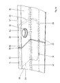
- each flange frame 14, 14 ' has an inner flange leg 16 or 16' resting on the inside of the associated channel section 10 or 12 and an outer flange leg 18 or 18 which projects approximately radially from the channel section 10, 12 ' on.
- the outer flange legs 18, 18 ' are formed continuously as a hollow profile, while of the inner flange legs 16, 16' only one of the abutting surface 19 of the butt joint arranged between the two flange frames 14, 14 'is designed as a hollow profile.
- This hollow profile part 20, 20 ' is extended into the interior of the channel sections 10, 12 as a flat, compressed double-walled profile part 22 or 22'.
- the flat profile parts 22, 22 ' are fixedly connected to the end of each channel section 10 or 12 by spot welding 24 or 24'.
- the hollow profile parts 18, 18 'and 20, 20' of the flange frame 14, 14 ' are filled in by the outer legs 26, 26' and inner legs 28 and 28 ', respectively, of L-shaped intermediate connectors generally designated 30 and 30' in the areas in which two ends of the flange frames 14, 14 'come together, as explained in more detail below.
- the outer legs 26, 26 'of the intermediate connectors 30, 30' and the associated areas of the outer profile legs 18, 18 'of the flange frames 14, 14' have openings 32 and 32 ', respectively, through which bolts 34 are guided, which are on the opposite side are held by nuts 36.
- Between the flange frame 14, 14 'sealing strips 38 made of elastic sealing compound are arranged, which run around the entire butt joint.
- the ends 40 and 40 'of the channel sections 10, 12 are also embedded in continuous sealing beads 42 and 42' made of elastic sealing material, which in the corners of the L-shaped profile of the flange frame 14, 14 'or in between the individual Flange frame sections lying areas in the corner of the profile of the intermediate connector 30, 30 'is arranged.
- this form of butt joint is suitable for any type of Round, flat oval or rectangular sheet metal ducts are excellently suitable, both in terms of stability and the continuous sealing of the butt joint.
- recesses 44 and 44 ' are provided on the side of the outer legs of the flange frame sections 14, 14' which points away from the abutment surface and which somewhat simplify the production of the profile and affect the stability of the arrangement only slightly because of the much greater stability of the intermediate connector 30.
- the higher stability of the closed embodiment shown in FIG. 2 is preferable. It should be noted that the same reference numerals are used for the same or corresponding parts in this and all subsequent embodiments.
- the outer flange leg 18 additionally has a triangular hollow profile 46 pointing away from the abutting surface of the channel sections 10, 12, which forms a channel 48 with the channel wall 10 to protect the sealing bead 42 and to guide the channel wall 10.
- the trough 48 can receive the spiral folds and spiral ribs, which are not shown and which project outward from the channel wall 10.
- the surface 50 of the triangular hollow profile 46 pointing towards the channel wall of the channel section 10 runs obliquely inwards towards the abutting surface and the channel wall 10 has wavy bulges 52 which press against the inner leg 28 of the intermediate connector profile.
- the undulating course of this wall 50 with the bulges 52 is shown in a detail in FIG. 5.
- the inclined wall 50 can also have trapezoidal or other shaped teeth 54 which press the channel wall 10 against the inner leg 28. Both the bulges 52 and the teeth 54 can, when the channel section 10 is pushed in, the winding folds or stiffening ribs, which are not shown and which stand outwards (ie upwards in the figures) dodge elastically or snap behind them. This does not impede the insertion or a distortion of channel walls or flange profiles.
- the hollow profile of the outer flange leg 18 is combined with the additional triangular hollow profile 46 to form a continuous hollow profile.
- the intermediate connector 30 has a chamfered edge 56, which is fitted into the triangular hollow profile 46 and points obliquely inwards and which provides an additional stiffening of the butt joint.
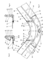
- FIG. 8 shows the embodiment shown in FIG. 2 in the area of an intermediate connector in a partial oblique view, the channel section 10 being omitted.
- Two ends 58 and 60, respectively, of a flange frame 14 that is bent together in one piece or of two successive flange frame sections 14, 14 ′′ are held in their position by the intermediate connector 30 inserted into the open profile ends 58 and 60.
- the intermediate connector 30 is only inserted with its end sections 62, 64 into the hollow profiles of the flange frame sections 14, 14 ′′, while an exposed middle section 66 contains the opening 32 which receives the screw bolt, not shown.
- the exposed inner leg 28 of the intermediate connector 30 lies approximately on the inside of the channel section 10, not shown, and, if greater stability is desired, can be attached to it.
- the sealing bead 42 runs in any case without gaps in the region of the flange frame sections 14, 14 ′′ and the central section 66 of the intermediate connector 30. Since the entire end edge of the channel section 10 is embedded in this sealing bead, a seal that can be achieved with known butt joints is difficult to achieve reached.
- the exemplary embodiment according to FIG. 9 differs from that of FIGS. 2 and 8 in that the inner leg 28 'in the central section 66 of the intermediate connector 30 extends to the end 68 of the inner leg 16 of the flange frame sections 14 and 14' and is flush with the outside of the inner flange leg is designed so that it fits snugly on a relatively large area on the inner surface of the channel portion 10, not shown, and can be attached to this if desired.
- FIG. 10 An embodiment is shown in which the two ends 58 and 60 of the flange frame sections 14 and 14 ′′ collide and the intermediate connector 30 is completely accommodated in the two hollow profiles of the flange frame.
- the opening 32 for receiving a screw bolt also penetrates the hollow profile walls of the one flange frame section 14 ′′.
- FIGS. 8 to 10 serve primarily for round or flat oval channels and flange frames.
- the exemplary embodiment shown in FIGS. 11 to 13 is suitable for rectangular channels with rounded corners, such a corner area being shown in FIG. 11.
- the two flange frame sections 14 and 14 ′′ are connected to one another by an intermediate connector 30 bent by 90 °, which is inserted with its two end sections 62 and 64 into the open profile ends 58, 60 of the flange frame sections 14, 14 ′′ and with its exposed middle section 66 forms a rounded corner of the flange frame.
- the intermediate connector 30 in this embodiment has a bevelled edge 56 which points away from the abutment surface 19 (see FIG. 1) which is not shown in FIGS. 11 to 13. That is fitted into the corresponding triangular hollow profile 46 of the flange frame sections 14, 14 ′′.
- the intermediate connector 30 has an elongated and thickened inner leg 28 ′ of the central section 66, which on the outside, on which the channel wall 10 (not shown) rests, is flush with the inner leg 16 of the flange frame sections 14, 14 '' transforms.
- the continuous sealing bead 42 is also omitted in FIG. 11. Both this sealing bead 42 and the channel section 10 omitted in FIG. 11 are, however, shown in the sectional representations of FIGS. 12 and 13.
- an opening 32 for receiving a screw bolt is provided approximately in the middle of the central section 66 of the intermediate connector 30 such that it passes through the outer profile leg 26 of the intermediate connector and the folded edge 56.
- the intermediate connector is flattened in the manner shown in FIGS. 11 and 13, so that the folded edge 56 rests on the outer profile leg 26. This results in good stability in the region 70 and a good fit of the screw bolt on the intermediate connector 30.
- FIG. 14 shows a part of an embodiment with a flat oval channel cross section, the intermediate connector 30 in this embodiment being bent by 180 ° in its central section 66, which is free of the substantially straight flange frame sections 14 and 14 ′′.
- the lengthened and thickened Formation of the inner profile leg 28 'in the central region 66 is particularly important, since the hold achieved by the relatively short, into the open profile ends of the flange frame sections 14 and 14''end sections 62 and 64 would be too small if the channel section 10, not shown, were not additionally on extended and directly against the inside of the channel section inner leg 28 'could not be additionally held and attached to it.
- the cross-sectional shape of the intermediate connector 30 in particular the beveled edge 56 ', which, in contrast to the beveled edge 56 pointing away from the abutment surface according to FIGS. 11 to 13, to that in FIG. 15 below and in FIGS 16 and 17 to the right, not shown butting surface 19 (see FIG. 1).
- the folded edge 56 ' is connected to the remaining part of the intermediate connector 30 via a web 57 which runs perpendicular to the abutting surface.
- the embodiment according to FIG. 18 is similar to the embodiment according to FIG. 14, but here, too, the flattened points 70 and 70 'do not have a folded edge 56', so that a simple flat cross section of the flange leg 26 results in these areas, as shown in Fig. 17.
- the rising, slowly bulging transition regions 71 and 71 ' are provided on both sides following the flat regions 70 and 70'.
- the embodiment according to FIG. 18 corresponds to the details of the embodiment according to FIG. 14.
- a sheet metal section 74, 74 ' which bears against the inside of the tubular channel section 10 (10' is omitted for the sake of clarity) is provided, the one to the abutting surface 19 indicative free edge to form an annular web 76, 76 'is angled outwards.
- the ring web 76 is bent into the position 76 ′′ shown in dashed lines and as a result its free edge 78 spreads out on the inside of the pipe section 10, whereby the flange frame 14 on the pipe section 10 against pulling out is largely determined.
- the tube section 10 is pressed into a desired circular shape by the prestressing of the ring web 76.
- the right flange frame 14 ' shows the state before driving into a pipe section, not shown.
- the ring web 76 itself takes over the sealing function in this embodiment and the attachment of a separate sealing bead can be omitted.
- a very similar embodiment can also be used in accordance with FIG. 20 for straight-walled air duct sections 10, 12, the flange frames 14, 14 'not being held together by a clamping ring but, as in the embodiment in accordance with FIG. 1, by means of screw bolts not shown in FIG. 20.
- this embodiment of course, no angled ring web 76, 76 'is required, but rather the sheet metal section 75, 75' resting on the inside of the air duct sections 10, 12 terminates in a straight line.
- the fixation on the air duct sections 10, 12 takes place here again by means of welding spots 24, 24 '.
Abstract
Eine Stoßverbindung zwischen zwei Luftkanalabschnitten (10,12) aus Blech weist zwei durch Schraubverbindungen (34,36) aneinander festzulegende Flanschrahmen (14,14') mit Zwischenverbindern (30,30') auf, die ihrerseits an den Enden aufeinanderstoßender Kanalabschnitte befestigt sind. Ein etwa radialer äußerer Flanschschenkel (14,14') und ein innerer Flanschschenkel (16,16') sind wenigstens teilweise als L-förmiges Hohlprofil ausgebildet, in welches das ebenfalls L-förmige Profil der Zwischenverbinder eingepaßt ist. <IMAGE>A butt joint between two air duct sections (10, 12) made of sheet metal has two flange frames (14, 14 ') to be fixed to one another by screw connections (34, 36) with intermediate connectors (30, 30'), which in turn are fastened to the ends of abutting duct sections. An approximately radial outer flange leg (14, 14 ') and an inner flange leg (16, 16') are at least partially designed as an L-shaped hollow profile into which the L-shaped profile of the intermediate connector is also fitted. <IMAGE>
Description
Die Erfindung betrifft eine Stoßverbindung zwischen zwei runden, flachovalen oder rechteckigen Luftkanalabschnitten aus Blech nach dem Oberbegriff des Anspruchs 1.The invention relates to a butt joint between two round, flat oval or rectangular air duct sections made of sheet metal according to the preamble of claim 1.
Im Luftkanalbau sind zahlreiche verschiedene Ausführungsformen von Stoßverbindungen zwischen den einzelnen Abschnitten eines Luftkanals bekannt, wobei jeweils unterschiedliche Flanschrahmen zum Verbinden von rechteckigen, runden oder flachovalen Luftkanälen verwendet werden müssen, um einerseits billige Herstellung und Montage und andererseits ausreichende Stabilität und Abdichtung zu erzielen. Außerdem ist im Luftkanalbau eine Wandlung im Gange, indem immer mehr von aus Blechtafeln abgekanteten, gebogenen und gefalzten Blechkanälen zu aus Blechbändern gewickelten Kanälen übergegangen wird. Ausgehend von dem altbekannten runden sog. Wickelfalzrohr bzw. Spiralfalzrohr stellte man durch Spreizung dieser runden Rohre Rohre mit flachovalem Querschnitt her, und neuerdings gibt es auch gewickelte Rechteckkanäle mit leicht gerundeten Ecken. Die gewickelten Kanäle haben zahlreiche Vorteile, wie Luftdichtigkeit ohne besondere Dichtungsmaßnahmen, automatische kontinuierliche Fertigung, beliebige Längen der einzelnen Luftkanalabschnitte, wobei meist eine Länge von 6 m üblich ist, und infolgedessen eine enorme Ersparnis von Flanschen und Montagezeit. Flachovale und rechteckige Querschnitte verwendet man deshalb bevorzugt, weil in den meisten Gebäuden die Raumhöhe nicht für größere runde Rohre ausreicht.In air duct construction, numerous different embodiments of butt connections between the individual sections of an air duct are known, wherein different flange frames must be used in each case for connecting rectangular, round or flat oval air ducts in order to achieve cheap manufacture and assembly on the one hand and sufficient stability and sealing on the other hand. In addition, a change is underway in air duct construction, in which more and more is being transitioned from sheet metal bends, bent and folded sheet metal ducts to ducts wound from sheet metal strips. Starting from the well-known round so-called spiral-seam tube or spiral-seam tube, pipes with a flat oval cross section were produced by spreading these round tubes ago, and recently there are also wound rectangular channels with slightly rounded corners. The wound ducts have numerous advantages, such as airtightness without special sealing measures, automatic continuous production, any length of the individual air duct sections, a length of 6 m is usually customary, and as a result an enormous saving in flanges and assembly time. Flat oval and rectangular cross sections are preferred because in most buildings the room height is not sufficient for larger round pipes.
Andererseits treten bei Wickelfalzrohren und daraus hergestellten flachovalen bzw. rechteckigen Kanälen bei Anbringung eines Flanschrahmens am Ende eines Luftkanalabschnitts Probleme wegen des spiralig um das Rohr verlaufenden Wickelfalzes auf. Bei allen gewickelten Rohren und Kanälen liegt der Falz außen, da er im Kanalinneren den Luftstrom behindern würde. Gewickelte Rohre und Kanäle haben deshalb nur eine glatte Innenseite, während aus Blechtafeln hergestellte Kanäle außen und innen glatt sind. Vergrößert wird das Problem noch dadurch, daß man bei flachovalen und rechteckigen gewickelten Kanälen, aber auch bei runden Wickelfalzrohren immer mehr den sog. Stehfalz oder auch zusätzliche Rippen zur Versteifung der Kanalflächen einsetzt, um Blechdicke einzusparen. Diese Stehfalz- bzw. Rippenversteifung ist besonders bei rechteckigen und flachovalen gewickelten Kanälen nötig, da hier die Stabilisierung durch Wölbung wegfällt, welche beim Rundrohr sehr hilfreich ist.On the other hand, problems arise in the case of folded spiral-seam pipes and flat oval or rectangular ducts made therefrom when a flange frame is attached to the end of an air duct section because of the spiral fold extending around the pipe. For all coiled pipes and ducts, the fold is on the outside, as it would hinder the air flow inside the duct. Coiled pipes and ducts therefore only have a smooth inside, while ducts made from sheet metal are smooth on the outside and inside. The problem is exacerbated by the fact that with flat oval and rectangular wound ducts, but also with round spiral ducts, the so-called standing seam or additional ribs are used to stiffen the duct surfaces in order to save sheet thickness. This standing seam or rib stiffening is particularly necessary in the case of rectangular and flat-oval wound ducts, since here the stabilization due to curvature is eliminated, which is very helpful with the round tube.
Wegen dieser unregelmäßigen Vorsprünge auf der Außenfläche gewickelter Kanäle und Rohre ist es unmöglich, die Kanalwand wie beim herkömmlichen Rechteckkanal in den Spalt eines auf das Rohr- oder Kanalende aufzusetzenden Flanschprofils zur Herstellung der Stoßverbindung einzustecken. Es ist daher nur möglich, ein im wesentlichen L-förmiges Flanschprofil mit einem etwa radial nach außen stehenden Flanschschenkel und einem an der Innenseite des Rohres oder Kanals anliegenden und an dieser Innenseite befestigten Flanschschenkel zu verwenden und eine Abdichtung zwischen Flanschprofil und Kanalende vorzusehen. Für Rundrohre ist eine Ausführungsform bekannt, bei der der innere Flanschschenkel des Flanschprofils durch einen Spreizrand an der Innenseite des Rohrs festgelegt ist. Bei einem flachovalen oder rechteckigen Kanal funktioniert eine solche Festlegung des Flanschrahmens jedoch nicht mehr, sondern dieser muß am Blechkanal durch Punktschweißung, Verschraubung oder Vernietung befestigt werden. Eine Abdichtung erfolgt dann durch Einbetten des Endes der Kanalwandung in eine Raupe aus Dichtungsmasse am Flanschprofil. Diese Ausführungsformen haben den Nachteil, daß bei Rundrohren zwischen den Enden des rundgebogenen Flanschrahmens und bei flachovalen oder rechteckigen Kanälen zwischen den einzelnen Abschnitten des Flanschrahmens durch Zwischenverbinder Spalte entstehen, die nicht in dieser einfachen Weise abzudichten sind. Ferner besteht hier der Nachteil, daß ein L-förmiges Profil ohne zusätzliche Stabilisierungseinrichtungen dem Zug der die beiden Flanschrahmen zu einer Stoßverbindung zusammenziehenden Schraubbolzen kaum standhält. Für rechteckige Wickelkanäle mit gerundeten Ecken eignen sich alle diese bekannten Stoßverbindungen nicht, da ein die gerundete Ecke überbrückender "Eckverbinder" in bekannten Ausführungsformen eine sehr lange nicht abgedichtete Strecke zwischen den einzelnen Flanschrahmenabschnitten aufwiese und ebenfalls dem Zug der Verbindungsschraubbolzen nicht standhalten könnte.Because of these irregular protrusions on the outer surface of wound ducts and pipes, it is impossible to insert the duct wall into the gap of a flange profile to be placed on the pipe or duct end to produce the butt joint, as in the case of the conventional rectangular duct. It is therefore only possible to have an essentially L-shaped flange profile to be used with an approximately radially outwardly projecting flange leg and a flange leg lying against the inside of the tube or channel and fastened to this inside and to provide a seal between the flange profile and the channel end. For round tubes, an embodiment is known in which the inner flange leg of the flange profile is fixed by an expansion rim on the inside of the tube. In the case of a flat oval or rectangular duct, however, such a fixing of the flange frame no longer works, but this must be fastened to the sheet metal duct by spot welding, screwing or riveting. Sealing is then carried out by embedding the end of the channel wall in a bead of sealant on the flange profile. These embodiments have the disadvantage that in the case of round tubes between the ends of the curved flange frame and in the case of flat oval or rectangular channels between the individual sections of the flange frame, gaps are formed by intermediate connectors, which gaps cannot be sealed in this simple manner. There is also the disadvantage that an L-shaped profile without additional stabilizing means can hardly withstand the tension of the bolts that pull the two flange frames together to form a butt joint. All these known butt joints are not suitable for rectangular winding channels with rounded corners, since a "corner connector" bridging the rounded corner in known embodiments had a very long non-sealed distance between the individual flange frame sections and could likewise not withstand the pull of the connecting screw bolts.
Ferner ist bei allen erwähnten Stoßverbindungsarten der Nachteil zu berücksichtigen, daß bei den Zwischenverbindern zwischen den einzelnen Flanschabschnitten, die gemeinsam einen Flanschrahmen bilden, der nicht abgedichtete Abstand dadurch noch wesentlich vergrößert wird, daß das Flanschprofil einige mm kleiner angefertigt werden muß als das Kanalinnere, damit man den inneren Flanschschenkel überhaupt ins Kanalinnere einführen kann und den unvermeidlichen Abweichungen der Kanalinnenabmessungen Rechnung getragen wird. Beim Befestigen des Flanschrahmens wird deshalb der Zwischenverbinder etwas aus dem Flanschprofil herausgezogen, damit der innere Flanschprofilschenkel satt an der Kanalinnenseite anliegen kann.Furthermore, the disadvantage of all the abovementioned types of butt joints is to be taken into account that, in the case of the intermediate connectors between the individual flange sections, which together form a flange frame, the unsealed distance is considerably increased in that the flange profile must be made a few mm smaller than the inside of the channel so that the inner flange leg can be inserted into the inside of the channel and the inevitable deviations of the inside dimensions of the channel are taken into account. When attaching the flange frame, the intermediate connector is therefore pulled out of the flange profile somewhat so that the inner flange profile leg can fit snugly against the inside of the duct.
Durch die Erfindung soll eine Stoßverbindung der eingangs genannten Art geschaffen werden, die sowohl für runde, ovale oder rechteckige Luftkanalabschnitte gleich gut verwendbar ist und trotz Herstellung des Luftkanals durch das Wickelverfahren und den dadurch notwendigen Falzen und ggf. Versteifungsrippen eine durchgehende einwandfreie Abdichtung der Flanschrahmen einschließlich Zwischenverbindern an den Enden der Kanalabschnitte ermöglicht.The invention is intended to create a butt joint of the type mentioned at the outset, which can be used equally well for round, oval or rectangular air duct sections and, despite the production of the air duct by the winding process and the necessary folds and stiffening ribs, including a continuous, perfect sealing of the flange frame Allows intermediate connectors at the ends of the channel sections.
Diese Aufgabe wird erfindungsgemäß durch die Merkmale des Anspruchs 1 gelöst.This object is achieved by the features of claim 1.
Durch die wenigstens teilweise Ausbildung jedes Flanschschenkels des Flanschprofils als L-förmiges Hohlprofil und das Einfügen eines satt in diesem Hohlprofil sitzenden L-förmigen Zwischenverbinders wird einerseits gewährleistet, daß die Flanschrahmen den Zug der Verbindungseinrichtungen, wie Verbindungsbolzen oder Spannringen, im wesentlichen ohne Verzerrung aushalten und daß andererseits eine durchlaufende Abdichtung des Kanalabschnittendes gegen den Flanschrahmen auch im Bereich des an der Innenseite des Kanalabschnittendes unmittelbar anliegenden inneren Profilschenkels des Zwischenverbinders möglich ist. Es kommt nicht mehr auf irgendwelche Toleranzen zwischen dem Kanalende und dem Flanschrahmen einschließlich der winkelförmigen oder entsprechend rundgebogenen Zwischenverbinder an, um eine gute durchlaufende Abdichtung zu erzielen. Die erfindungsgemäße Stoßverbindung ist für alle Arten von runden, flachovalen oder rechteckigen Luftkanälen in gleicher Weise anwendbar, wodurch sich Herstellung und Lagerhaltung enorm vereinfachen. Es spielt bei dieser Art von Stoßverbindung keine Rolle mehr, ob der Zwischenverbinder ganz in die offenen Enden der anschließenden Abschnitte des Flanschrahmens eingeführt wird, so daß die Profilenden der Flanschabschnitte zusammenstoßen, oder ob ein Mittelteil des Zwischenverbinders freiliegt. In beiden Fällen kann z.B. eine Dichtungsraupe nahtlos um den ganzen Flanschrahmen laufen.The at least partial design of each flange leg of the flange profile as an L-shaped hollow profile and the insertion of an L-shaped intermediate connector that fits snugly in this hollow profile ensures on the one hand that the flange frame can withstand the pull of the connecting devices, such as connecting bolts or clamping rings, essentially without distortion and that, on the other hand, a continuous sealing of the end of the duct section against the flange frame is also possible in the region of the inner profile leg of the intermediate connector which lies directly against the inside of the end of the duct section. There is no longer any need for any tolerances between the channel end and the flange frame, including the angular or correspondingly curved intermediate connectors, in order to ensure a good continuous Achieve sealing. The butt joint according to the invention can be used in the same way for all types of round, flat oval or rectangular air ducts, which enormously simplifies manufacture and storage. With this type of butt joint, it no longer matters whether the intermediate connector is fully inserted into the open ends of the adjoining sections of the flange frame so that the profile ends of the flange sections meet, or whether a middle part of the intermediate connector is exposed. In both cases, for example, a sealing bead can run seamlessly around the entire flange frame.
Besonders zweckmäßig ist eine Ausführungsform nach Anspruch 2, bei der die an der Innenseite der Kanalwandung unmittelbar anliegenden Mittelabschnitte der Zwischenverbinder einen Teil des Zuges der Verbindungsschrauben aufnehmen, so daß der Zug der Verbindungsschrauben nicht mehr voll von den Flanschrahmenschenkeln aufgenommen werden muß, sondern zum großen Teil von den Zwischenverbindern selbst getragen wird. Dadurch erhöht sich die Stabilität der gesamten Stoßverbindung.An embodiment according to claim 2 is particularly expedient, in which the middle sections of the intermediate connectors which are directly adjacent to the inside of the channel wall absorb part of the tension of the connecting screws, so that the tension of the connecting screws no longer has to be fully absorbed by the flange frame legs, but largely is borne by the intermediate connectors themselves. This increases the stability of the entire butt joint.
Eine noch größere Stabilität ergibt sich, wenn gemäß Anspruch 3 die inneren Flanschschenkel über das Hohlprofil hinaus verlängert werden und somit eine größere Auflagefläche an der Kanalinnenseite erzielt wird. Insbesondere können gemäß Anspruch 4 zum gleichen Zweck die Mittelabschnitte der Zwischenverbinder verlängert werden. Eine besonders hohe Stabilität ergibt sich, wenn nach Anspruch 5 diese Mittelabschnitte unmittelbar an der Kanalwandung befestigt werden.An even greater stability is obtained if, according to claim 3, the inner flange legs are extended beyond the hollow profile and thus a larger contact surface is achieved on the inside of the channel. In particular, according to claim 4, the middle sections of the intermediate connectors can be extended for the same purpose. A particularly high stability is obtained if, according to claim 5, these middle sections are attached directly to the channel wall.
Nach Anspruch 6 kann eine Dichtungsraupe bei der erfindungsgemäßen Stoßverbindung lückenlos um den gesamten Flanschrahmen einschließlich der Zwischenverbinder verlaufen, was die einfachste und sicherste Art einer Abdichtung darstellt.According to claim 6, a sealing bead in the butt joint according to the invention can run seamlessly around the entire flange frame including the intermediate connector, which is the simplest and safest type of Represents sealing.
Anspruch 7 stellt besonders heraus, daß die erfindungsgemäße Stoßverbindung für Zwischenverbinder jeder Art, insbesondere gerade, gebogene oder winkelförmige Zwischenverbinder, gleichermaßen gut anwendbar ist.Claim 7 particularly emphasizes that the butt joint according to the invention for intermediate connectors of any kind, in particular straight, curved or angular intermediate connectors, is equally well applicable.
Der zusätzlichen Versteifung und Stabilisierung der Stoßverbindung dienen die Maßnahmen nach den Ansprüchen 8 bis 11, wobei insbesondere die wellenförmigen Ausbuchtungen bzw. Zähne gemäß Anspruch 10 ein elastisch federndes Andrücken der Kanalwandung gegen den inneren Profilschenkel des Zwischenverbinders gewährleistet, wobei nach außen stehende Wickelfalze und/oder Rippen federnd von diesen Ausbuchtungen oder Zähnen aufgenommen bzw. unter diesen durchgeschoben werden können.The additional stiffening and stabilization of the butt joint serve the measures according to claims 8 to 11, wherein in particular the wave-shaped bulges or teeth according to
Grundsätzlich können die die Schraubbolzen der Stoßverbindung aufnehmenden Durchbrüche an beliebiger Stelle jedes Flanschrahmens angeordnet werden, d.h. also in den freiliegenden Mittelabschnitten der Zwischenverbinder oder aber in den Enden der einzelnen Flanschabschnitte sowie den diese ausfüllenden Endabschnitten der Zwischenverbinder. Bei Ausführungsformen nach den Ansprüchen 11 bis 13, bei denen zur weiteren Versteifung ein abgekanteter Rand des äußeren Profilschenkels des Zwischenverbinders vorgesehen ist, kann gemäß Anspruch 14 der Zwischenverbinder im Bereich der Durchbrüche abgeflacht sein, um eine größere Steifheit und Widerstandskraft des Zwischenverbinders und/oder ein gutes Sitzen der Bolzenköpfe bzw. Muttern zu gewährleisten. Die Abflachung kann nach Anspruch 15 durch Zusammendrücken des abgekanteten Randes bzw. durch Weglassen dieses Randes in den abgeflachten Bereichen von vornherein erreicht werden.Basically, the openings receiving the bolts of the butt joint can be arranged at any point on each flange frame, i.e. that is, in the exposed central sections of the intermediate connectors or in the ends of the individual flange sections and in the end sections of the intermediate connectors filling them. In embodiments according to claims 11 to 13, in which a bent edge of the outer profile leg of the intermediate connector is provided for further stiffening, according to claim 14 the intermediate connector can be flattened in the area of the openings to provide greater stiffness and resistance of the intermediate connector and / or to ensure that the bolt heads or nuts are properly seated. The flattening can be achieved from the outset by compressing the folded edge or by omitting this edge in the flattened areas.
Bei runden Luftkanalabschnitten kann gemäß den Ansprüchen 16 und 17 die Festlegung des Flanschrahmens am Luftkanalabschnitt besonders zweckmäßig durch einen an der Innenseite des Rundrohrs unter Vorspannung eingespreizten Ringsteg erfolgen, der an sich aus der DE-PS 31 43 893 bekannt ist.In the case of round air duct sections, according to
Anhand der Figuren werden Ausführungsbeispiele der Erfindung näher erläutert. Es zeigen
- Fig. 1
- einen axialen Teilschnitt durch eine erste Ausführungsform der erfindungsgemäßen Stoßverbindung,
- Fig. 2
- einen nur ein Kanalende und einen Flanschrahmen umfassenden schematisch vereinfachten axialen Teilschnitt durch eine zweite Ausführungsform,
- Fig. 3 u. 4
- der Fig. 2 entsprechende schematische Teilschnitte durch weitere Ausführungsformen,
- Fig. 5 u. 6
- Teilschrägansichten von zwei Ausführungsformen einer Profilwand der in 4 dargestellten Ausführungsform,
- Fig. 7
- einen der Fig. 2 entsprechenden schematischen Teilschnitt durch eine weitere Ausführungsform,
- Fig. 8
- eine Teilschrägansicht der in Fig. 2 gezeigten Ausführungsform im Bereich eines Zwischenverbinders, wobei zur besseren Übersichtlichkeit die Kanalwandung weggelassen ist,
- Fig. 9 bis 11, 14, 15 und 18
- der Fig. 8 entsprechende Teilschrägansichten weiterer Ausführungsformen,
- Fig. 12
- einen Schnitt längs der Linie XII-XII in Fig. 11,
- Fig. 13
- einen Schnitt längs der Linie XIII-XIII in Fig. 11,
- Fig. 16
- einen Schnitt längs der Linie XVI-XVI in Fig. 15,
- Fig. 17
- einen Schnitt längs der Linie XVII-XVII in Fig. 15,
- Fig. 19
- einen der Fig. 1 entsprechenden axialen Teilschnitt durch eine für Rundrohre geeignete Ausführungsform mit Spreizrand und Spannring und
- Fig. 20
- die gleiche Ausführungsform ohne Spreizrand und Spannring.
- Fig. 1
- an axial partial section through a first embodiment of the butt joint according to the invention,
- Fig. 2
- 1 shows a schematically simplified partial axial section through only one channel end and a flange frame through a second embodiment,
- Fig. 3 u. 4th
- 2 corresponding schematic partial sections through further embodiments,
- Fig. 5 u. 6
- Partial oblique views of two embodiments of a profile wall of the embodiment shown in FIG. 4,
- Fig. 7
- 2 shows a schematic partial section corresponding to FIG. 2 through a further embodiment,
- Fig. 8
- 3 shows a partial oblique view of the embodiment shown in FIG. 2 in the area of an intermediate connector, the channel wall being omitted for better clarity,
- 9 to 11, 14, 15 and 18th
- 8 corresponding partial oblique views of further embodiments,
- Fig. 12
- a section along the line XII-XII in Fig. 11,
- Fig. 13
- a section along the line XIII-XIII in Fig. 11,
- Fig. 16
- a section along the line XVI-XVI in Fig. 15,
- Fig. 17
- a section along the line XVII-XVII in Fig. 15,
- Fig. 19
- an axial partial section corresponding to FIG. 1 through an embodiment suitable for round tubes with an expanding rim and clamping ring and
- Fig. 20
- the same embodiment without a spreading rim and clamping ring.
Bei der in Fig. 1 dargestellten Ausführungsform der Stoßverbindung ist jeweils ein Endteil eines Blechkanalabschnitts 10 bzw. 12 dargestellt, wobei an jedem Kanalabschnittende ein allgemein mit 14 bzw. 14' bezeichneter Flanschrahmen befestigt ist. Jeder Flanschrahmen 14, 14' weist in dem in Fig. 1 gezeigten Profil einen an der Innenseite des zugehörigen Kanalabschnitts 10 bzw. 12 anliegenden inneren Flanschschenkel 16 bzw. 16' und einen vom Kanalabschnitt 10, 12 etwa radial abstehenden äußeren Flanschschenkel 18 bzw. 18' auf. Die äußeren Flanschschenkel 18, 18' sind durchgehend als Hohlprofil ausgebildet, während vom inneren Flanschschenkel 16, 16' nur ein der zwischen den beiden Flanschrahmen 14, 14' angeordneten Stoßfläche 19 der Stoßverbindung nahegelegener Teil 20 bzw. 20' als Hohlprofil ausgebildet ist. Dieser Hohlprofilteil 20, 20' ist ins Innere der Kanalabschnitte 10, 12 als flach zusammengedrückter doppelwandiger Profilteil 22 bzw. 22' verlängert. Die flachen Profilteile 22, 22' sind durch Punktschweißung 24 bzw. 24' mit dem Ende jedes Kanalabschnitts 10 bzw. 12 fest verbunden.In the embodiment of the butt joint shown in FIG. 1, an end part of a sheet
Die Hohlprofilteile 18, 18' und 20, 20' der Flanschrahmen 14, 14' sind von den äußeren Schenkeln 26, 26' bzw. inneren Schenkeln 28 bzw. 28' von allgemein mit 30 bzw. 30' bezeichneten, L-förmigen Zwischenverbindern in den Bereichen ausgefüllt, in denen zwei Enden der Flanschrahmen 14, 14' zusammenkommen, wie weiter unten näher erläutert. Die äußeren Schenkel 26, 26' der Zwischenverbinder 30, 30' sowie die zugehörigen Bereiche der äußeren Profilschenkel 18, 18' der Flanschrahmen 14, 14' weisen Durchbrüche 32 bzw. 32' auf, durch die Schraubbolzen 34 geführt sind, die auf der Gegenseite durch Muttern 36 festgehalten sind. Zwischen den Flanschrahmen 14, 14' sind Dichtungsstreifen 38 aus elastischer Dichtungsmasse angeordnet, die rings um die gesamte Stoßverbindung verlaufen. Die Enden 40 bzw. 40' der Kanalabschnitte 10, 12 sind in ebenfalls lückenlos durchlaufende Dichtungsraupen 42 bzw. 42' aus elastischem Dichtungsmaterial eingebettet, welche in den Ecken des L-förmigen Profils der Flanschrahmen 14, 14' bzw. in den zwischen den einzelnen Flanschrahmenabschnitten liegenden Bereichen in der Ecke des Profils der Zwischenverbinder 30, 30' angeordnet ist.The
Da der Zug der verbindenden Schraubenbolzen 34 bei der erfindungsgemäßen Stoßverbindung außer vom Profil der Flanschrahmenabschnitte 14, 14' vor allem von den die Flanschrahmenhohlprofile ausfüllenden, wesentlich kräftigeren L-förmigen Zwischenverbindern 30, 30' aufgenommen wird, ist diese Form der Stoßverbindung für jede Art von runden, flachovalen oder rechteckigen Blechkanälen hervorragend geeignet, sowohl was die Stabilität als auch die durchgehende Abdichtung der Stoßverbindung anbetrifft.Since the pull of the connecting
Bei der in Fig. 1 dargestellten Ausführungsform sind an der von der Stoßfläche wegweisenden Seite der äußeren Schenkel der Flanschrahmenabschnitte 14, 14' Aussparungen 44 bzw. 44' vorgesehen, welche die Herstellung des Profils etwas vereinfachen und die Stabilität der Anordnung wegen der wesentlich größeren Stabilität der Zwischenverbinder 30 nur unwesentlich beeinflussen. Bei Ausführungsformen mit längeren geraden Flanschrahmenabschnitten zwischen den einzelnen Zwischenverbindern ist jedoch die höhere Stabilität der in Fig. 2 dargestellten geschlossenen Ausführungsform vorzuziehen. Es ist zu beachten, daß bei dieser und allen folgenden Ausführungsformen für gleiche oder entsprechende Teile die gleichen Bezugszeichen verwendet sind.In the embodiment shown in FIG. 1, recesses 44 and 44 'are provided on the side of the outer legs of the
Bei der in Fig. 3 dargestellten Ausführungsform weist der äußere Flanschschenkel 18 zusätzlich ein von der Stoßfläche der Kanalabschnitte 10, 12 wegweisendes dreieckförmiges Hohlprofil 46 auf, das mit der Kanalwand 10 eine Rinne 48 zum Schutz der Dichtungsraupe 42 und zur Führung der Kanalwand 10 bildet. Außerdem kann die Rinne 48 die nicht gezeigten von der Kanalwand 10 nach außen stehenden Spiralfalze und Spiralrippen aufnehmen.In the embodiment shown in FIG. 3, the
Bei der Ausführungsform gemäß Fig. 4 verläuft die zur Kanalwandung des Kanalabschnitts 10 hinweisende Fläche 50 des dreieckförmigen Hohlprofils 46 zur Stoßfläche hin schräg nach innen und weist die Kanalwandung 10 gegen den inneren Schenkel 28 des Zwischenverbinderprofils drückende wellenförmige Ausbuchtungen 52 auf. Der wellenförmige Verlauf dieser Wandung 50 mit den Ausbuchtungen 52 ist in einem Ausschnitt in Fig. 5 näher dargestellt.In the embodiment according to FIG. 4, the
Statt der wellenförmigen Ausbuchtungen kann die schräge Wandung 50 auch trapezförmige oder anders geformte Zähne 54 aufweisen, welche die Kanalwandung 10 gegen den inneren Schenkel 28 drücken. Sowohl die Ausbuchtungen 52 als auch die Zähne 54 können beim Einschieben des Kanalabschnitts 10 den nicht dargestellten, nach außen (d.h. also in den Figuren nach oben) stehenden Wickelfalzen bzw. Versteifungsrippen elastisch ausweichen bzw. hinter denselben einschnappen. Eine Behinderung des Einschiebens oder eine Verzerrung von Kanalwänden oder Flanschprofil erfolgt dadurch nicht.Instead of the wave-shaped bulges, the
Bei der in Fig. 7 dargestellten Ausführungsform ist das Hohlprofil des äußeren Flanschschenkels 18 mit dem zusätzlichen dreieckförmigen Hohlprofil 46 zu einem durchgehenden Hohlprofil zusammengefaßt. Der Zwischenverbinder 30 weist bei dieser Ausführungsform einen in das dreieckförmige Hohlprofil 46 eingepaßten abgekanteten und schräg nach innen weisenden Rand 56 auf, der für eine zusätzliche Versteifung der Stoßverbindung sorgt.In the embodiment shown in FIG. 7, the hollow profile of the
Aus Fig. 8 ist die in Fig. 2 dargestellte Ausführungsform im Bereich eines Zwischenverbinders in Teilschrägansicht zu sehen, wobei der Kanalabschnitt 10 weggelassen ist. Zwei Enden 58 bzw. 60 eines entweder aus einem Stück zusammengebogenen Flanschrahmens 14 oder von zwei aufeinanderfolgenden Flanschrahmenabschnitten 14, 14'' sind durch den in die offenen Profilenden 58 und 60 eingesteckten Zwischenverbinder 30 in ihrer Lage gehalten. Der Zwischenverbinder 30 ist dabei nur mit seinen Endabschnitten 62, 64 in die Hohlprofile der Flanschrahmenabschnitte 14, 14'' eingeschoben, während ein freiliegender Mittelabschnitt 66 den den nicht gezeigten Schraubbolzen aufnehmenden Durchbruch 32 enthält. Der freiliegende innere Schenkel 28 des Zwischenverbinders 30 liegt dabei in etwa an der Innenseite des nicht gezeigten Kanalabschnitts 10 an und kann, wenn größere Stabilität gewünscht wird, an diesem befestigt werden. Die Dichtungsraupe 42 läuft, wie oben erläutert, in jedem Falle lückenlos im Bereich der Flanschrahmenabschnitte 14, 14'' und des Mittelabschnitts 66 des Zwischenverbinders 30 durch. Da in diese Dichtungsraupe die gesamte Endkante des Kanalabschnitts 10 eingebettet ist, ist eine bei bekannten Stoßverbindungen nur mit großem Aufwand zu erzielende Abdichtung erreicht.FIG. 8 shows the embodiment shown in FIG. 2 in the area of an intermediate connector in a partial oblique view, the
Das Ausführungsbeispiel gemäß Fig. 9 unterscheidet sich von demjenigen der Figuren 2 und 8 dadurch, daß der innere Schenkel 28' im Mittelabschnitt 66 des Zwischenverbinders 30 bis zum Ende 68 des inneren Schenkels 16 der Flanschrahmenabschnitte 14 und 14' verlängert und bündig mit der Außenseite des inneren Flanschschenkels ausgeführt ist, so daß er auf einer verhältnismäßig großen Fläche satt an der Innenfläche des nicht gezeigten Kanalabschnitts 10 anliegt und gewünschtenfalls an diesem befestigt werden kann.The exemplary embodiment according to FIG. 9 differs from that of FIGS. 2 and 8 in that the inner leg 28 'in the
In Fig. 10 ist eine Ausführungsform dargestellt, bei der die beiden Enden 58 und 60 der Flanschrahmenabschnitte 14 und 14'' zusammenstoßen und der Zwischenverbinder 30 vollständig in die beiden Hohlprofile des Flanschrahmens aufgenommen ist. In diesem Falle durchsetzt der Durchbruch 32 zur Aufnahme eines nicht gezeigten Schraubbolzens auch die Hohlprofilwände des einen Flanschrahmenabschnitts 14''.An embodiment is shown in FIG. 10 in which the two ends 58 and 60 of the
Da bei rechteckigen Kanalquerschnitten normalerweise geradlinige Flanschrahmenabschnitte durch als Eckwinkelstücke ausgebildete Zwischenverbinder miteinander verbunden werden, dienen die in den Fig. 8 bis 10 dargestellten Ausführungsformen vorwiegend für runde oder flachovale Kanäle und Flanschrahmen.Since, in the case of rectangular channel cross sections, normally straight flange frame sections are connected to one another by intermediate connectors designed as corner angle pieces, the embodiments shown in FIGS. 8 to 10 serve primarily for round or flat oval channels and flange frames.
Das in den Fig. 11 bis 13 gezeigte Ausführungsbeispiel ist für rechteckige Kanäle mit abgerundeten Ecken geeignet, wobei ein solcher Eckbereich in Fig. 11 gezeigt ist. Die beiden Flanschrahmenabschnitte 14 und 14'' sind durch einen um 90° gebogenen Zwischenverbinder 30 miteinander verbunden, der mit seinen beiden Endabschnitten 62 und 64 in die offenen Profilenden 58,60 der Flanschrahmenabschnitte 14, 14'' eingesteckt ist und mit seinem freiliegenden Mittelabschnitt 66 eine abgerundete Ecke des Flanschrahmens bildet. Wie beim Ausführungsbeispiel der Fig. 7 weist der Zwischenverbinder 30 bei dieser Ausführungsform einen abgekanteten Rand 56 auf, der von der in Fig. 11 bis 13 nicht gezeigten Stoßfläche 19 (s. Fig. 1) wegweist. Der in das entsprechende dreieckförmige Hohlprofil 46 der Flanschrahmenabschnitte 14, 14'' eingepaßt ist. Ferner weist der Zwischenverbinder 30 wie beim Ausführungsbeispiel der Fig. 9 einen verlängerten und verdickten inneren Schenkel 28' des Mittelabschnitts 66 auf, der an der Außenseite, auf der die nicht gezeigte Kanalwand 10 aufliegt, bündig in die inneren Schenkel 16 der Flanschrahmenabschnitte 14, 14'' übergeht. Auch die durchlaufende Dichtungsraupe 42 ist in Fig. 11 weggelassen. Sowohl diese Dichtungsraupe 42 als auch der in Fig. 11 weggelassene Kanalabschnitt 10 sind jedoch in die Schnittdarstellungen der Fig. 12 und 13 eingezeichnet.The exemplary embodiment shown in FIGS. 11 to 13 is suitable for rectangular channels with rounded corners, such a corner area being shown in FIG. 11. The two
Bei dieser Ausführungsform ist ein Durchbruch 32 zur Aufnahme eines nicht gezeigten Schraubbolzens etwa in der Mitte des Mittelabschnitts 66 des Zwischenverbinders 30 derart vorgesehen, daß er den äußeren Profilschenkel 26 des Zwischenverbinders und den abgekanteten Rand 56 durchsetzt. In dem den Durchbruch 32 enthaltenden Bereich 70 ist der Zwischenverbinder in der aus den Fig. 11 und 13 ersichtlichen Weise abgeflacht, so daß der abgekantete Rand 56 am äußeren Profilschenkel 26 anliegt. Dadurch ergibt sich im Bereich 70 eine gute Stabilität und ein guter Sitz des Schraubbolzens am Zwischenverbinder 30.In this embodiment, an
In Fig. 14 ist ein Teil einer Ausführungsform mit flachovalem Kanalquerschnitt dargestellt, wobei der Zwischenverbinder 30 bei dieser Ausführungsform in seinem von den im wesentlichen geradlinigen Flanschrahmenabschnitten 14 und 14'' freien Mittelabschnitt 66 um 180° gebogen ist. Bei dieser Ausführungsform ist die verlängerte und verdickte Ausbildung des inneren Profilschenkels 28' im Mittelbereich 66 besonders wichtig, da der durch die verhältnismäßig kurzen, in die offenen Profilenden der Flanschrahmenabschnitte 14 und 14'' ragenden Endabschnitte 62 und 64 erzielte Halt zu gering wäre, wenn der nicht gezeigte Kanalabschnitt 10 nicht zusätzlich am verlängerten und unmittelbar an der Innenseite des Kanalabschnitts anliegenden inneren Schenkel 28' nicht zusätzlich gehalten und daran befestigt werden könnte. Bei dieser Ausführungsform sind statt des einen Durchbruchs der Ausführungsform gemäß Fig. 11 bis 13 nahe den Enden des Mittelbereichs 66 zwei Durchbrüche 32, 32' für nicht gezeigte Schraubbolzen in jeweils abgeflachten Bereichen 70 bzw. 70' des äußeren Profilschenkels 26, 56 vorgesehen. Bei kleineren flachovalen Kanälen könnte auch nur ein Durchbruch 32 in der Mitte des Mittelabschnitts 66 vorgesehen werden wie bei der oben geschilderten Ausführungsform gemäß Fig. 11 bis 13.FIG. 14 shows a part of an embodiment with a flat oval channel cross section, the
Das Ausführungsbeispiel gemäß Fig. 15 bis 17 ist dem in den Figuren 11 bis 13 gezeigten ähnlich. Es unterscheidet sich von diesem vorangehenden Ausführungsbeispiel jedoch durch die Querschnittsform der Zwischenverbinder 30, insbesondere des abgekanteten Randes 56', der im Gegensatz zu dem von der Stoßfläche wegweisenden abgekanteten Rand 56 gemäß Fig. 11 bis 13 zu der in Fig. 15 unten und in den Fig. 16 und 17 rechts zu denkenden, nicht eingezeichneten Stoßfläche 19 (s. Fig. 1) hinweist. Der abgekantete Rand 56' ist bei dieser Ausführungsform über einen senkrecht zur Stoßfläche verlaufenden Steg 57 mit dem übrigen Teil des Zwischenverbinders 30 verbunden. Im abgeflachten Bereich 70 ist bei dieser Ausführungsform der abgekantete Rand 56' und somit natürlich auch der senkrechte Steg 57 weggelassen, so daß sich in diesem Bereich, wie aus Fig. 17 zu ersehen, ein flacher, ebener, parallel zur Stoßfläche 19 verlaufender Querschnitt des Flanschschenkels 26 ergibt. Diese Form des Zwischenverbinders ist noch einfacher herzustellen als die in den Fig. 11 bis 13 gezeigte Ausführungsform und wird daher für viele Anwendungsfälle bevorzugt. Vom abgeflachten Bereich 70 ergibt sich dann beidseitig ein Übergangsbereich 71 bzw. 71', in welchem der flache Flanschschenkelquerschnitt sich aufwölbt, um kurz vor dem offenen Profilende 58, 60 die Querschnittsform gemäß Fig. 16 mit abgekantetem Rand 56' und Steg 57 zu erreichen. Im übrigen entsprechend die Darstellungen der Fig. 15 bis 17 den Darstellungen in den Fig. 11 bis 13.15 to 17 is similar to that shown in FIGS. 11 to 13. It differs from this preceding exemplary embodiment, however, by the cross-sectional shape of the
Ebenso ist die Ausführungsform gemäß Fig. 18 ähnlich der Ausführungsform gemäß Fig. 14, wobei jedoch auch hier die abgeflachten Stellen 70 bzw. 70' keinen abgekanteten Rand 56' aufweisen, so daß sich in diesen Bereichen ein einfacher flacher Querschnitt des Flanschschenkels 26 ergibt, wie er in Fig. 17 dargestellt ist. Die ansteigenden, sich langsam aufwölbenden Übergangsbereiche 71 bzw. 71' sind bei dieser Ausführungsform jeweils zu beiden Seiten anschließend an die flachen Bereiche 70 bzw. 70' vorgesehen. Im übrigen entspricht die Ausführungsform gemäß Fig. 18 den Einzelheiten der Ausführungsform gemäß Fig. 14.Likewise, the embodiment according to FIG. 18 is similar to the embodiment according to FIG. 14, but here, too, the flattened
Bei der für Rundrohre geeigneten Ausführungsform gemäß Fig. 19 werden in einer aus der DE-PS 33 41 107 bekannten Art die beiden Flanschrahmen 14 und 14' durch einen auf ihre Außenseite aufgesetzen und festgezogenen Spannring 72 fest aneinander gehalten, dessen Funktion hier nicht näher erläutert werden muß. Die Flanschrahmen 14, 14' durchsetzende Schraubbolzen sind hier nicht erforderlich. Zur deutlicheren Sichtbarkeit der Form des Flanschrahmens 14 ist nur in den rechten Flanschrahmen 14' ein Zwischenverbinder 30 mit abgekantetem Rand 56' gemäß der Ausführungsform von Fig. 16 eingezeichnet, während der linke Flanschrahmen 14 in der Darstellung der Fig. 19 leergelassen ist. Alle Teile des Flanschrahmens 14' und des Zwischenverbinders 57' sind gegenüber der Darstellung in Fig. 16 mit den entsprechenden, mit einem Strich versehenen Bezugszahlen bezeichnet.19 suitable for round tubes in a manner known from DE-PS 33 41 107, the two flange frames 14 and 14 'are held firmly against one another by a clamping
Bei dieser Ausführungsform ist vom Ende des flachen Profilteils 22, 22' der inneren Flanschschenkel 16, 16' ein an der Innenseite des rohrförmigen Kanalabschnitts 10 (10' ist der deutlicheren Darstellung halber weggelassen) anliegender Blechabschnitt 74, 74' vorgesehen, dessen zur Stoßfläche 19 hinweisender freier Rand zur Bildung eines Ringstegs 76, 76' nach außen abgewinkelt ist. Wenn der Flanschring 14 in das offene Ende des Rohrabschnitts 10 eingetrieben wird, wird der Ringsteg 76 in die gestrichelt eingezeichnete Lage 76'' gebogen und infolgedessen spreizt sich seine freie Kante 78 an der Innenseite des Rohrabschnitts 10 ein, wodurch der Flanschrahmen 14 am Rohrabschnitt 10 gegen ein Herausziehen weitgehend festgelegt wird. Gleichzeitig wird durch die Vorspannung des Ringstegs 76 der Rohrabschnitt 10 in eine gewünschte Kreisform gedrückt. Beim rechten Flanschrahmen 14' ist der Zustand vor dem Eintreiben in einen nicht dargestellten Rohrabschnitt gezeigt. Durch das Einspreizen seiner freien Kante 78 an der Innenseite des Rohrabschnitts 10 übernimmt der Ringsteg 76 bei dieser Ausführungsform selbst die Dichtfunktion und die Anbringung einer gesonderten Dichtraupe kann entfallen.In this embodiment, from the end of the
Nahe dem Ende 40 des Rohrabschnitts 10 sind aus der Wandung des Rohrabschnitts einzelne Abstützvorsprünge 80 nach innen gedrückt, hinter denen die Außenkante 78 des Ringstegs 76 eingeschnappt ist, was zu einer zusätzlichen Sicherung des Flanschrahmens 14 am Rohrabschnitt 10 führt. Allerdings setzt diese Ausführungsform Rohrabschnitte mit sauberen und glatten Innenflächen im Randbereich voraus. Falls der innere Randbereich nicht sauber bzw. uneben ist, kommen nur Ausführungsformen mit Dichtraupe in Betracht. Jedoch können sowohl für die Herstellung einer Ausführungsform mit schrägem Ringsteg 76 als auch ohne schrägen Ringsteg dieselben Werkzeuge verwendet werden, da der schräge Ringsteg auf jeden Fall mit hergestellt und sodann einfach wieder eingedrückt werden kann. Dieses Eindrücken kann im gleichen Werkzeug durch einen zusätzlich eingeschalteten Biegebacken oder dgl. erfolgen.Near the
Eine sehr ähnliche Ausführungsform kann gemäß Fig. 20 auch bei geradwandigen Luftkanalabschnitten 10, 12 angewendet werden, wobei die Flanschrahmen 14, 14' nicht durch einen Spannring, sondern wie bei der Ausführungsform gemäß Fig. 1 durch in Fig 20 nicht gezeigte Schraubbolzen zusammengehalten werden. Bei dieser Ausführungsform ist natürlich kein abgewinkelter Ringsteg 76, 76' erforderlich, sondern der an der Innenseite der Luftkanalabschnitte 10, 12 anliegende Blechabschnitt 75, 75' läuft geradlinig aus. Die Festlegung an den Luftkanalabschnitten 10, 12 erfolgt hier wiederum durch Schweißpunkte 24, 24'. Durch die dreifache Lage von Blechabschnitten in den flach zusammengedrückten Profilteilen 22 und 22' ergibt sich im Zusammenhang mit den übrigen Merkmalen dieser Ausführungsform eine äußerst stabile Ausgestaltung der Stoßverbindung.A very similar embodiment can also be used in accordance with FIG. 20 for straight-walled
Claims (17)
Applications Claiming Priority (4)
| Application Number | Priority Date | Filing Date | Title |
|---|---|---|---|
| DE4005139 | 1990-02-17 | ||
| DE4005139 | 1990-02-17 | ||
| DE4023470 | 1990-07-24 | ||
| DE4023470A DE4023470C2 (en) | 1990-02-17 | 1990-07-24 | Butt joint between two air duct sections made of sheet metal |
Publications (3)
| Publication Number | Publication Date |
|---|---|
| EP0443193A2 true EP0443193A2 (en) | 1991-08-28 |
| EP0443193A3 EP0443193A3 (en) | 1992-02-26 |
| EP0443193B1 EP0443193B1 (en) | 1993-09-22 |
Family
ID=25890287
Family Applications (1)
| Application Number | Title | Priority Date | Filing Date |
|---|---|---|---|
| EP90125318A Expired - Lifetime EP0443193B1 (en) | 1990-02-17 | 1990-12-22 | Butt connection between two duct sections of sheet metal |
Country Status (13)
| Country | Link |
|---|---|
| US (1) | US5133580A (en) |
| EP (1) | EP0443193B1 (en) |
| JP (1) | JPH0823398B2 (en) |
| AT (1) | ATE94961T1 (en) |
| AU (1) | AU634628B2 (en) |
| CA (1) | CA2034879C (en) |
| DE (2) | DE4023470C2 (en) |
| DK (1) | DK0443193T3 (en) |
| ES (1) | ES2046663T3 (en) |
| FI (1) | FI92097C (en) |
| IE (1) | IE65889B1 (en) |
| NO (1) | NO178591C (en) |
| RU (1) | RU1831642C (en) |
Cited By (5)
| Publication number | Priority date | Publication date | Assignee | Title |
|---|---|---|---|---|
| FR2732443A1 (en) * | 1995-03-31 | 1996-10-04 | Aral Profilage | Connection for two heating or ventilation duct sections |
| WO2008073837A2 (en) * | 2006-12-08 | 2008-06-19 | Jeffrey Allen Hermanson | Rectangular/ square spiral ducting systems with flange connectors and method of making the same |
| US9061342B2 (en) | 2009-11-24 | 2015-06-23 | Jeffrey Allen Hermanson | Standing seam connectors for ducting |
| US9101969B2 (en) | 2002-02-01 | 2015-08-11 | Jeffrey Allen Hermanson | Rectangular/square spiral ducting systems with flange connectors |
| US10539337B2 (en) | 2009-11-24 | 2020-01-21 | Jeffrey Allen Hermanson | Sealed and/or reinforced flanged ring connector for single- and double-wall HVAC ducting |
Families Citing this family (24)
| Publication number | Priority date | Publication date | Assignee | Title |
|---|---|---|---|---|
| US5423576A (en) * | 1992-01-10 | 1995-06-13 | Industrial Air, Inc. | Corner pieces for improved duct connector |
| US5356184A (en) * | 1992-01-10 | 1994-10-18 | Industrial Air, Inc. | Corner pieces for improved duct connector |
| US5378028A (en) * | 1993-01-25 | 1995-01-03 | Mez Industries, Inc. | Apparatus for connecting oval duct sections |
| NL9500127A (en) * | 1994-04-22 | 1995-12-01 | Waal Staal Bv De | Device for butt connection of gaseous medium-carrying channels with a rectangular or square cross-section. |
| US5470112A (en) * | 1994-10-24 | 1995-11-28 | Keating Koupling, Inc. | Adjustable coupling ring |
| DE19547982A1 (en) * | 1995-12-21 | 1997-06-26 | Meinig Metu System | Butt joint of air duct sections |
| WO2001042666A2 (en) * | 1999-12-02 | 2001-06-14 | Ovalformer Llc | Hvac flange and flange machine |
| US6505864B1 (en) * | 2001-07-03 | 2003-01-14 | Ductmate Industries, Inc. | Fabricated oval duct connector |
| DE10215112C1 (en) | 2002-04-05 | 2003-09-25 | Meinig Metu System | Abutting pipe connection uses clamping device for securing annular edges of coupling flanges at ends of abutting pipe sections together |
| US7195290B2 (en) * | 2003-11-13 | 2007-03-27 | William Christopher Duffy | Apparatus for a fire-rated duct |
| ES1057983Y (en) * | 2004-07-13 | 2005-01-16 | Navarro Josep Ramisa | SEGMENT PUMP DEVICE FOR AIR DUCTS |
| DE202005021845U1 (en) | 2005-09-29 | 2010-08-19 | Meyer, Heinrich, Dipl.-Ing. | Arrangement for connecting channel modules or sections for gaseous media |
| KR100669496B1 (en) * | 2006-06-08 | 2007-01-16 | (주)대양씨에스피 | Jointing apparatus of steel ribbed pipes |
| US9212770B2 (en) | 2007-07-18 | 2015-12-15 | RAM Developing, LLC | Method and apparatus for attaching flange portions to ducts |
| US8276425B2 (en) * | 2007-10-02 | 2012-10-02 | Mestek Machinery, Inc. | Ductmaking apparatus |
| KR100870678B1 (en) * | 2007-11-29 | 2008-11-26 | (주)대양기연 | Track type smoke prevention duct and method of execution |
| US8499604B2 (en) * | 2008-10-01 | 2013-08-06 | Mestek Machinery, Inc. | Duct making apparatus and method |
| CN103988006B (en) * | 2011-11-14 | 2016-11-16 | 双叶产业株式会社 | The welding connection structure of pipe |
| US9074788B2 (en) | 2012-01-06 | 2015-07-07 | William Christopher Duffy | Fire-rated modular duct assembly suitable for exhausting flammable or hazardous gases, vapours and other materials |
| US10024569B2 (en) | 2013-10-10 | 2018-07-17 | William Christopher Duffy | Fire-rated modular duct assembly and improvements therein |
| US9849317B2 (en) | 2015-01-26 | 2017-12-26 | Honeywell International Inc. | Duct systems including shield and flange support |
| US10317000B2 (en) * | 2015-02-17 | 2019-06-11 | Shinfuji Kuuchou Co., Ltd. | Duct flange structure, and manufacturing method for the same |
| CN104913135A (en) * | 2015-06-08 | 2015-09-16 | 上海盛剑环境系统科技有限公司 | Quick connection flange |
| US10533689B2 (en) * | 2016-09-28 | 2020-01-14 | Ductmate Industries, Inc. | Double wall duct connector |
Citations (6)
| Publication number | Priority date | Publication date | Assignee | Title |
|---|---|---|---|---|
| DE1750133A1 (en) * | 1968-04-02 | 1971-03-11 | Rasmussen Gmbh | Flange connection for sheet metal ducts |
| DD145786A1 (en) * | 1979-08-27 | 1981-01-07 | Rainer Bott | CONNECTION OF PARTICULARS OF SQUARE AIR CHANNELS |
| EP0047467A1 (en) * | 1980-09-04 | 1982-03-17 | Karl Meinig KG | Flanged joint for conduit parts of sheet metal, especially for conduit parts of ducts |
| DE3143893C1 (en) * | 1981-11-05 | 1983-04-21 | Karl Meinig KG, 7201 Rietheim-Weilheim | Flange ring for pipes |
| EP0197466A2 (en) * | 1985-04-06 | 1986-10-15 | METU-System Meinig KG | Air duct portion with tip stretched connecting flange |
| EP0354627A1 (en) * | 1988-08-12 | 1990-02-14 | Casparus Wilhelmus De Waal | Method for preparing a corner profile fit for butting connection of closed channels |
Family Cites Families (14)
| Publication number | Priority date | Publication date | Assignee | Title |
|---|---|---|---|---|
| US574743A (en) * | 1897-01-05 | Edwakd j | ||
| US565499A (en) * | 1896-08-11 | Richard pattison | ||
| DE379002C (en) * | 1921-02-22 | 1923-08-10 | Oscar Lehmann G | Portable electric vacuum cleaner |
| US2703109A (en) * | 1951-08-25 | 1955-03-01 | Gen Dynamics Corp | Duct construction |
| AT336357B (en) * | 1975-07-08 | 1977-05-10 | Vmw Ranshofen Berndorf Ag | PROFILE FLANGE FOR SLIDING ON DUCTS, PIPES AND THE LIKE. |
| DE7618115U1 (en) * | 1976-06-05 | 1977-11-24 | Schmolz + Bickenbach, 4000 Duesseldorf | Prefabricated flange connection for air conditioning ducts |
| CH632328A5 (en) * | 1977-11-09 | 1982-09-30 | Guenter Smitka | FLANGE CONNECTION. |
| CA1105521A (en) * | 1979-05-04 | 1981-07-21 | Georg Mez | Air-conducting passages |
| BE892865A (en) * | 1982-04-15 | 1982-08-02 | Houze Jean Pierre | Frame element for gaseous fluid trunking - has mortise jointing for quick fit assembly of frame and trunking |
| US4537425A (en) * | 1982-05-11 | 1985-08-27 | Umc Industries, Inc. | High integrity flange connection arrangement |
| US4542923A (en) * | 1983-12-07 | 1985-09-24 | Crosse Frank X | Duct jointing system |
| BE901841A (en) * | 1985-02-28 | 1985-08-28 | Smiths Peter A H | Air-conditioning duct connector - has flexible connector-band of L=shaped cross-section engaging beaded edge rims on duct sections |
| DE3515737A1 (en) * | 1985-05-02 | 1986-11-06 | Karl Meinig KG, 7201 Rietheim-Weilheim | FLANGE RING FOR PIPES |
| US5015018A (en) * | 1988-06-10 | 1991-05-14 | Ductmate Industries, Inc. | Duct connector |
-
1990
- 1990-07-24 DE DE4023470A patent/DE4023470C2/en not_active Expired - Fee Related
- 1990-12-22 DK DK90125318.7T patent/DK0443193T3/en active
- 1990-12-22 EP EP90125318A patent/EP0443193B1/en not_active Expired - Lifetime
- 1990-12-22 DE DE90125318T patent/DE59002848D1/en not_active Expired - Fee Related
- 1990-12-22 ES ES199090125318T patent/ES2046663T3/en not_active Expired - Lifetime
- 1990-12-22 AT AT90125318T patent/ATE94961T1/en not_active IP Right Cessation
-
1991
- 1991-01-22 NO NO910257A patent/NO178591C/en unknown
- 1991-01-24 CA CA002034879A patent/CA2034879C/en not_active Expired - Fee Related
- 1991-01-29 JP JP3009124A patent/JPH0823398B2/en not_active Expired - Lifetime
- 1991-02-08 FI FI910636A patent/FI92097C/en active IP Right Grant
- 1991-02-15 RU SU914894445A patent/RU1831642C/en active
- 1991-02-15 IE IE53791A patent/IE65889B1/en not_active IP Right Cessation
- 1991-02-15 AU AU71073/91A patent/AU634628B2/en not_active Ceased
- 1991-02-19 US US07/656,715 patent/US5133580A/en not_active Expired - Lifetime
Patent Citations (6)
| Publication number | Priority date | Publication date | Assignee | Title |
|---|---|---|---|---|
| DE1750133A1 (en) * | 1968-04-02 | 1971-03-11 | Rasmussen Gmbh | Flange connection for sheet metal ducts |
| DD145786A1 (en) * | 1979-08-27 | 1981-01-07 | Rainer Bott | CONNECTION OF PARTICULARS OF SQUARE AIR CHANNELS |
| EP0047467A1 (en) * | 1980-09-04 | 1982-03-17 | Karl Meinig KG | Flanged joint for conduit parts of sheet metal, especially for conduit parts of ducts |
| DE3143893C1 (en) * | 1981-11-05 | 1983-04-21 | Karl Meinig KG, 7201 Rietheim-Weilheim | Flange ring for pipes |
| EP0197466A2 (en) * | 1985-04-06 | 1986-10-15 | METU-System Meinig KG | Air duct portion with tip stretched connecting flange |
| EP0354627A1 (en) * | 1988-08-12 | 1990-02-14 | Casparus Wilhelmus De Waal | Method for preparing a corner profile fit for butting connection of closed channels |
Cited By (9)
| Publication number | Priority date | Publication date | Assignee | Title |
|---|---|---|---|---|
| FR2732443A1 (en) * | 1995-03-31 | 1996-10-04 | Aral Profilage | Connection for two heating or ventilation duct sections |
| US9101969B2 (en) | 2002-02-01 | 2015-08-11 | Jeffrey Allen Hermanson | Rectangular/square spiral ducting systems with flange connectors |
| WO2008073837A2 (en) * | 2006-12-08 | 2008-06-19 | Jeffrey Allen Hermanson | Rectangular/ square spiral ducting systems with flange connectors and method of making the same |
| WO2008073837A3 (en) * | 2006-12-08 | 2008-11-20 | Jeffrey Allen Hermanson | Rectangular/ square spiral ducting systems with flange connectors and method of making the same |
| GB2457414A (en) * | 2006-12-08 | 2009-08-19 | Jeffrey Allen Hermanson | Rectangular/square spiral ducting systems with flange connectors and method of making the same |
| GB2457414B (en) * | 2006-12-08 | 2011-03-30 | Jeffrey Allen Hermanson | Rectangular/square spiral ducting systems with flange connectors |
| US9061342B2 (en) | 2009-11-24 | 2015-06-23 | Jeffrey Allen Hermanson | Standing seam connectors for ducting |
| US10539337B2 (en) | 2009-11-24 | 2020-01-21 | Jeffrey Allen Hermanson | Sealed and/or reinforced flanged ring connector for single- and double-wall HVAC ducting |
| US11953225B2 (en) | 2009-11-24 | 2024-04-09 | Jeffrey Allen Hermanson | Sealed and/or reinforced flanged ring connector for single- and double-wall HVAC ducting |
Also Published As
| Publication number | Publication date |
|---|---|
| DE4023470C2 (en) | 1994-05-19 |
| JPH0823398B2 (en) | 1996-03-06 |
| FI92097C (en) | 1994-09-26 |
| RU1831642C (en) | 1993-07-30 |
| NO178591C (en) | 1996-04-24 |
| ES2046663T3 (en) | 1994-02-01 |
| EP0443193B1 (en) | 1993-09-22 |
| FI92097B (en) | 1994-06-15 |
| ATE94961T1 (en) | 1993-10-15 |
| IE910537A1 (en) | 1991-08-28 |
| FI910636A0 (en) | 1991-02-08 |
| AU7107391A (en) | 1991-08-22 |
| NO178591B (en) | 1996-01-15 |
| EP0443193A3 (en) | 1992-02-26 |
| FI910636A (en) | 1991-08-18 |
| AU634628B2 (en) | 1993-02-25 |
| NO910257D0 (en) | 1991-01-22 |
| JPH04211786A (en) | 1992-08-03 |
| CA2034879A1 (en) | 1991-08-18 |
| US5133580A (en) | 1992-07-28 |
| DE4023470A1 (en) | 1991-08-22 |
| IE65889B1 (en) | 1995-11-29 |
| DK0443193T3 (en) | 1994-03-07 |
| CA2034879C (en) | 1997-07-29 |
| NO910257L (en) | 1991-08-19 |
| DE59002848D1 (en) | 1993-10-28 |
Similar Documents
| Publication | Publication Date | Title |
|---|---|---|
| EP0443193B1 (en) | Butt connection between two duct sections of sheet metal | |
| DE3512669C2 (en) | ||
| DE3428179A1 (en) | Sheet-metal channel system having means for connection of the ends of the individual channel sections, and corner connectors for making the connections | |
| EP0078946B1 (en) | Flanged ring for pipes | |
| DE19547982A1 (en) | Butt joint of air duct sections | |
| EP0148286A1 (en) | Flanged joint | |
| DE4308013A1 (en) | Flange ring that can be placed on a thin-walled sheet metal tube | |
| EP0381981A1 (en) | Connecting device for circumferentially ribbed pipes or hoses | |
| EP0296280B1 (en) | Beam for window frames | |
| DE102005000720B4 (en) | Pipe coupling Press | |
| EP2441998B1 (en) | Flexible section for a gas flow channel | |
| DE2802037C3 (en) | Device for holding together connecting flanges seated on air duct sections | |
| EP1357323B1 (en) | Device for forming a flexible connection | |
| DE2750110A1 (en) | Clip=on flange for rectangular box section duct - has hollow L=section with bar forming channel with double thickness walls housing duct edge | |
| EP0379002B1 (en) | Butt joint between two flat-oval sheet metal tube sections | |
| DE8525275U1 (en) | Profile strip seal made of elastic material for windows, doors or the like. | |
| DE3901394A1 (en) | Butt joint between two flat-oval ventilating-pipe lengths made of sheet metal | |
| DE60110705T2 (en) | System and method for connecting channels | |
| DE2517221C3 (en) | Pipe connections, in particular for ventilation systems | |
| DE7608213U1 (en) | CORNER BRACKETS FOR CONNECTING SPACER HOLLOW PROFILES FOR INSULATED GLAZING OF WINDOWS, DOORS OR DGL. | |
| DE3716136C2 (en) | Profile for flange connections of ventilation ducts | |
| DE4310284C2 (en) | Frame, especially door or window frame | |
| CH599493A5 (en) | Connecting nozzle for air conditioning plant ducts | |
| DE7734366U1 (en) | DEVICE FOR MUTUAL FASTENING OF SIGNIFICANTLY RECTANGULAR CHANNEL SECTIONS MADE OF SHEET METAL | |
| AT408003B (en) | Arrangement by means of which the joint forming between two concrete bodies is sealed |
Legal Events
| Date | Code | Title | Description |
|---|---|---|---|
| PUAI | Public reference made under article 153(3) epc to a published international application that has entered the european phase |
Free format text: ORIGINAL CODE: 0009012 |
|
| AK | Designated contracting states |
Kind code of ref document: A2 Designated state(s): AT BE CH DE DK ES FR GB IT LI LU NL SE |
|
| PUAL | Search report despatched |
Free format text: ORIGINAL CODE: 0009013 |
|
| AK | Designated contracting states |
Kind code of ref document: A3 Designated state(s): AT BE CH DE DK ES FR GB IT LI LU NL SE |
|
| 17P | Request for examination filed |
Effective date: 19920229 |
|
| 17Q | First examination report despatched |
Effective date: 19920902 |
|
| ITF | It: translation for a ep patent filed |
Owner name: FIAMMENGHI FIAMMENGHI RACHELI |
|
| GRAA | (expected) grant |
Free format text: ORIGINAL CODE: 0009210 |
|
| AK | Designated contracting states |
Kind code of ref document: B1 Designated state(s): AT BE CH DE DK ES FR GB IT LI LU NL SE |
|
| REF | Corresponds to: |
Ref document number: 94961 Country of ref document: AT Date of ref document: 19931015 Kind code of ref document: T |
|
| ET | Fr: translation filed | ||
| REF | Corresponds to: |
Ref document number: 59002848 Country of ref document: DE Date of ref document: 19931028 |
|
| GBT | Gb: translation of ep patent filed (gb section 77(6)(a)/1977) |
Effective date: 19930930 |
|
| EPTA | Lu: last paid annual fee | ||
| REG | Reference to a national code |
Ref country code: ES Ref legal event code: FG2A Ref document number: 2046663 Country of ref document: ES Kind code of ref document: T3 |
|
| REG | Reference to a national code |
Ref country code: DK Ref legal event code: T3 |
|
| PLBE | No opposition filed within time limit |
Free format text: ORIGINAL CODE: 0009261 |
|
| STAA | Information on the status of an ep patent application or granted ep patent |
Free format text: STATUS: NO OPPOSITION FILED WITHIN TIME LIMIT |
|
| 26N | No opposition filed | ||
| EAL | Se: european patent in force in sweden |
Ref document number: 90125318.7 |
|
| ITTA | It: last paid annual fee | ||
| REG | Reference to a national code |
Ref country code: GB Ref legal event code: IF02 |
|
| PGFP | Annual fee paid to national office [announced via postgrant information from national office to epo] |
Ref country code: LU Payment date: 20031230 Year of fee payment: 14 |
|
| PG25 | Lapsed in a contracting state [announced via postgrant information from national office to epo] |
Ref country code: LU Free format text: LAPSE BECAUSE OF NON-PAYMENT OF DUE FEES Effective date: 20041222 |
|
| PGFP | Annual fee paid to national office [announced via postgrant information from national office to epo] |
Ref country code: AT Payment date: 20051223 Year of fee payment: 16 |
|
| PGFP | Annual fee paid to national office [announced via postgrant information from national office to epo] |
Ref country code: NL Payment date: 20061218 Year of fee payment: 17 |
|
| PGFP | Annual fee paid to national office [announced via postgrant information from national office to epo] |
Ref country code: SE Payment date: 20061227 Year of fee payment: 17 |
|
| PGFP | Annual fee paid to national office [announced via postgrant information from national office to epo] |
Ref country code: DK Payment date: 20061228 Year of fee payment: 17 |
|
| PGFP | Annual fee paid to national office [announced via postgrant information from national office to epo] |
Ref country code: BE Payment date: 20070112 Year of fee payment: 17 |
|
| PG25 | Lapsed in a contracting state [announced via postgrant information from national office to epo] |
Ref country code: AT Free format text: LAPSE BECAUSE OF NON-PAYMENT OF DUE FEES Effective date: 20061222 |
|
| BERE | Be: lapsed |
Owner name: *METU-SYSTEM MEINIG K.G. Effective date: 20071231 |
|
| REG | Reference to a national code |
Ref country code: DK Ref legal event code: EBP |
|
| EUG | Se: european patent has lapsed | ||
| NLV4 | Nl: lapsed or anulled due to non-payment of the annual fee |
Effective date: 20080701 |
|
| PG25 | Lapsed in a contracting state [announced via postgrant information from national office to epo] |
Ref country code: BE Free format text: LAPSE BECAUSE OF NON-PAYMENT OF DUE FEES Effective date: 20071231 |
|
| PG25 | Lapsed in a contracting state [announced via postgrant information from national office to epo] |
Ref country code: SE Free format text: LAPSE BECAUSE OF NON-PAYMENT OF DUE FEES Effective date: 20071223 |
|
| PG25 | Lapsed in a contracting state [announced via postgrant information from national office to epo] |
Ref country code: NL Free format text: LAPSE BECAUSE OF NON-PAYMENT OF DUE FEES Effective date: 20080701 |
|
| PG25 | Lapsed in a contracting state [announced via postgrant information from national office to epo] |
Ref country code: DK Free format text: LAPSE BECAUSE OF NON-PAYMENT OF DUE FEES Effective date: 20080102 |
|
| PGFP | Annual fee paid to national office [announced via postgrant information from national office to epo] |
Ref country code: CH Payment date: 20081222 Year of fee payment: 19 |
|
| PGFP | Annual fee paid to national office [announced via postgrant information from national office to epo] |
Ref country code: ES Payment date: 20081219 Year of fee payment: 19 |
|
| PGFP | Annual fee paid to national office [announced via postgrant information from national office to epo] |
Ref country code: IT Payment date: 20081227 Year of fee payment: 19 |
|
| PGFP | Annual fee paid to national office [announced via postgrant information from national office to epo] |
Ref country code: FR Payment date: 20081216 Year of fee payment: 19 |
|
| PGFP | Annual fee paid to national office [announced via postgrant information from national office to epo] |
Ref country code: DE Payment date: 20090123 Year of fee payment: 19 |
|
| PGFP | Annual fee paid to national office [announced via postgrant information from national office to epo] |
Ref country code: GB Payment date: 20081118 Year of fee payment: 19 |
|
| REG | Reference to a national code |
Ref country code: CH Ref legal event code: PL |
|
| GBPC | Gb: european patent ceased through non-payment of renewal fee |
Effective date: 20091222 |
|
| REG | Reference to a national code |
Ref country code: FR Ref legal event code: ST Effective date: 20100831 |
|
| PG25 | Lapsed in a contracting state [announced via postgrant information from national office to epo] |
Ref country code: CH Free format text: LAPSE BECAUSE OF NON-PAYMENT OF DUE FEES Effective date: 20091231 Ref country code: LI Free format text: LAPSE BECAUSE OF NON-PAYMENT OF DUE FEES Effective date: 20091231 Ref country code: FR Free format text: LAPSE BECAUSE OF NON-PAYMENT OF DUE FEES Effective date: 20091231 |
|
| PG25 | Lapsed in a contracting state [announced via postgrant information from national office to epo] |
Ref country code: DE Free format text: LAPSE BECAUSE OF NON-PAYMENT OF DUE FEES Effective date: 20100701 |
|
| PG25 | Lapsed in a contracting state [announced via postgrant information from national office to epo] |
Ref country code: GB Free format text: LAPSE BECAUSE OF NON-PAYMENT OF DUE FEES Effective date: 20091222 |
|
| PG25 | Lapsed in a contracting state [announced via postgrant information from national office to epo] |
Ref country code: IT Free format text: LAPSE BECAUSE OF NON-PAYMENT OF DUE FEES Effective date: 20091222 |
|
| REG | Reference to a national code |
Ref country code: ES Ref legal event code: FD2A Effective date: 20110407 |
|
| PG25 | Lapsed in a contracting state [announced via postgrant information from national office to epo] |
Ref country code: ES Free format text: LAPSE BECAUSE OF NON-PAYMENT OF DUE FEES Effective date: 20110324 |
|
| PG25 | Lapsed in a contracting state [announced via postgrant information from national office to epo] |
Ref country code: ES Free format text: LAPSE BECAUSE OF NON-PAYMENT OF DUE FEES Effective date: 20091223 |