EP0443069A1 - Method of measuring the electric or magnetic field pattern with a sensor arrangement - Google Patents
Method of measuring the electric or magnetic field pattern with a sensor arrangement Download PDFInfo
- Publication number
- EP0443069A1 EP0443069A1 EP90103479A EP90103479A EP0443069A1 EP 0443069 A1 EP0443069 A1 EP 0443069A1 EP 90103479 A EP90103479 A EP 90103479A EP 90103479 A EP90103479 A EP 90103479A EP 0443069 A1 EP0443069 A1 EP 0443069A1
- Authority
- EP
- European Patent Office
- Prior art keywords
- current source
- vector
- activity
- determined
- field
- Prior art date
- Legal status (The legal status is an assumption and is not a legal conclusion. Google has not performed a legal analysis and makes no representation as to the accuracy of the status listed.)
- Withdrawn
Links
Images
Classifications
-
- G—PHYSICS
- G01—MEASURING; TESTING
- G01R—MEASURING ELECTRIC VARIABLES; MEASURING MAGNETIC VARIABLES
- G01R33/00—Arrangements or instruments for measuring magnetic variables
- G01R33/02—Measuring direction or magnitude of magnetic fields or magnetic flux
- G01R33/025—Compensating stray fields
Definitions
- the invention relates to a method for measuring the field pattern of electrical or magnetic fields with the aid of a sensor arrangement and with a data processing system for the iterative determination of the spatial position of a current source causing the field according to the preamble of patent claim 1.
- the measurement of magnetic fields that are weaker than the earth's magnetic field by several powers of ten has become particularly important in connection with biomagnetic activities.
- the aim is to measure the external fields emanating from nerve currents in the interior of a living organism with the aid of appropriate sensors at different locations and to determine the location of an equivalent dipole from the field pattern measured in this way with the aid of an appropriate data evaluation.
- the measuring equipment required for this must be extremely sensitive and special gradiometers are used, which are housed together with a superconducting quantum interferometer (SQUID) in a Dewar vessel under superconducting conditions.
- the external interference fields must also be shielded as well as possible.
- the patient and measuring device are housed in a walk-in magnetic shielding chamber.
- multi-channel systems have been developed, as described, for example, in the publication "Electromedica” 57, 1989, pages 2 to 7.
- an electro-physiological activity in this area generates an electric or magnetic field during a known period of time, the spatial field pattern of which remains approximately constant during this period, but changes by an amplitude factor as a function of time, for example slowly increases and decreases.
- the course of this temporal change in the amplitude factor is not known.
- Such a change occurs, for example, when an electro-physiological activity remains stable in location and direction, but the current density of the ion flow slowly decreases. For example, this is the case with the repolarization of the atria in the P / Q interval of the cardiac cycle.
- this background field pattern can be measured at a specific point in time before the onset of the activity that is to be localized and this activity would remain constant, subtracted from the field pattern to be measured. If, as is practically the case, the background activity does not remain constant during the measurement cycle to determine the activity to be determined, this simple subtraction method does not work.
- the invention is based on the object of a background activity of physiological or technical origin, the field pattern of which can be determined at a certain point in time before the onset of the activity to be measured, taking into account its amplitude profile during the duration of the measurement period to define that it can be subtracted from the total size in the correct size at any time.
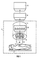
- the arrangement shown in FIG. 1 consists of a patient repository 1 for positioning the patient 2, a DEWAR vessel 4 arranged above the patient, which contains a multi-channel gradiometer arrangement and the DC-SQUIDS assigned to the gradiometers.
- Patient bed 1 and DEWAR vessel 4 are housed in a shielding chamber 7 against the action of external magnetic fields.
- An electronic unit 8 is used to control and power the SQUID gradiometer 5.
- the signal evaluation of the measured values determined by the SQUID gradiometers, the time profile of the magnetic field emanating from an equivalent dipole 10 and surrounding the patient's body 11 at the different measuring locations, takes place in a computer 9, according to a specific iteration algorithm.
- the measured magnetic field pattern is often not only generated by a single, spatially localizable current source. Rather, it happens that an activity, the current source of which is to be localized, is superimposed on another activity, which can originate, for example, from a pre-activity that diffuses over a larger tissue complex and with increasing or decaying amplitude and spreads over the field of those to be localized Current source superimposed.
- a background field is suitable for influencing the field pattern of interest in such a way that the evaluation leads to incorrect localization of the current source.
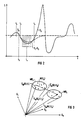
- FIG. 2 shows the temporal course of an external magnetic field (MKG) originating from a cardiac activity measured at the location of one of the gradiometers. Only a section (time window) of the curve should be considered. The time window begins at time t 1 and ends at time t 3. The activity decaying at time t 1 comes from the repolarization of the atria in the P / Q interval of the cardiac cycle. This is an activity whose magnetic field pattern remains approximately constant during this period, but changes by an amplitude factor, ie slowly increases and decreases. This change in the amplitude factor over time is not known. It occurs, for example, when an electro-physiological activity remains stable in place and direction, but the current density of the ion flow slowly decreases.
- MKG external magnetic field
- the amplitude of this activity S 1 decays accordingly.
- the ventricular activity S2 begins to be localized. Both activities overlap for the entire duration of the window.
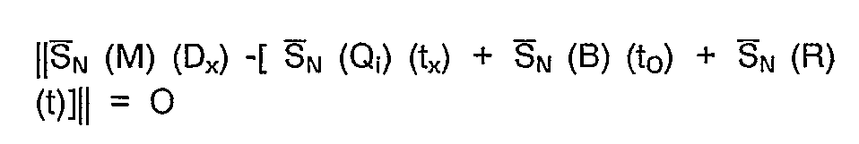
- the signal measured by the sensors at a time t can be described in vector form as follows:
- S ⁇ N (M) (t) S ⁇ N (Q) (t) + S ⁇ N (B) (t) + S ⁇ N (R) (t)
- the activity S 1 must be subtracted from the activity S 2. For this purpose, the activity S1 is first determined at a time t0 at which this still occurs alone.
- the measured value vector S N (M) describes a point in the measured value subspace MR 1.
- the entire measured value subspace is spanned by the signals in each of the three sensors G 1, G 2 and G 3 shown and has the dimension N, where N denotes the number of sensors. In reality, the number of sensors is much higher, for example 37.
- the signal S N (Q) of this predetermined model current source eg current dipole
- the search strategy now searches for those of all possible signal vectors of the current source S N (Q) the the current measured value S N (M) is closest.
Landscapes
- Physics & Mathematics (AREA)
- Condensed Matter Physics & Semiconductors (AREA)
- General Physics & Mathematics (AREA)
- Measurement And Recording Of Electrical Phenomena And Electrical Characteristics Of The Living Body (AREA)
- Measuring Magnetic Variables (AREA)
Abstract
Description
Die Erfindung betrifft ein Verfahren zur Messung des Feldmusters elektrischer oder magnetischer Felder mit Hilfe einer Sensoranordnung sowie mit einer Datenverarbeitungsanlage zur iterativen Ermittlung der räumlichen Lage einer das Feld verursachenden Stromquelle nach dem Oberbegriff des Patentanspruches 1.The invention relates to a method for measuring the field pattern of electrical or magnetic fields with the aid of a sensor arrangement and with a data processing system for the iterative determination of the spatial position of a current source causing the field according to the preamble of patent claim 1.
Die Messung von gegenüber dem Erdmagnetfeld um mehrere Zehnerpotenzen schwächerer Magnetfeldern hat besonders in Verbindung mit biomagnetischen Aktivitäten Bedeutung erlangt. Dabei geht es darum, die von Nervenströmen im Inneren eines lebenden Organismus ausgehenden Außenfelder mit Hilfe entsprechender Sensoren an verschiedenen Orten zu messen und aus dem so gemessenen Feldmuster mit Hilfe einer entsprechenden Datenauswertung den Ort eines äquivalenten Dipols zu ermitteln. Die dazu erforderlichen Meßeinrichtungen müssen außerordentlich empfindlich sein und man bedient sich dazu spezieller Gradiometer, die zusammen mit einem supraleitenden Quanteninterferrometer (SQUID) in einem Dewargefäß unter supraleitenden Bedingungen untergebracht sind. Um auf diese Weise eine aussagekräftige Messung zu ermöglichen, müssen vor allem auch die äußeren Störfelder bestmöglich abgeschirmt werden. Dazu werden Patient und Meßeinrichtung in einer begehbaren magnetischen Abschirmkammer untergebracht. Um die Feldverteilung möglichst rasch ermitteln zu können, sind Vielkanalsysteme entwickelt worden, wie sie beispielsweise in der Druckschrift "Electromedica" 57, 1989, Seiten 2 bis 7, beschrieben sind.The measurement of magnetic fields that are weaker than the earth's magnetic field by several powers of ten has become particularly important in connection with biomagnetic activities. The aim is to measure the external fields emanating from nerve currents in the interior of a living organism with the aid of appropriate sensors at different locations and to determine the location of an equivalent dipole from the field pattern measured in this way with the aid of an appropriate data evaluation. The measuring equipment required for this must be extremely sensitive and special gradiometers are used, which are housed together with a superconducting quantum interferometer (SQUID) in a Dewar vessel under superconducting conditions. In order to enable a meaningful measurement in this way, the external interference fields must also be shielded as well as possible. For this purpose, the patient and measuring device are housed in a walk-in magnetic shielding chamber. In order to be able to determine the field distribution as quickly as possible, multi-channel systems have been developed, as described, for example, in the publication "Electromedica" 57, 1989, pages 2 to 7.
Nun verfälschen aber nicht nur von außen einwirkende Störfelder das Meßergebnis. Es ist vielmehr häufig der Fall, daß die gesuchte, das äußere Magnetfeld verursachende bioelektrische Stromquelle von den Aktivitäten einer benachbarten Quelle additiv überlagert wird. Diese "Hintergrund-Aktivität" kann zu einem Fehler bei der Lokalisierung der gesuchten Stromquelle führen. Dieser Fall tritt insbesondere bei den biomagnetischen Herzaktivitäten (Magnetokardiogramm) auf. Wenn ein solches überlagertes Feld ausreichend bekannt ist, kann es vom gemessenen Feld subtrahiert werden, um das Feld der gesuchten Stromquelle zu erhalten. Eine solche konstante Aktivität ist aber insbesondere bei den Reizströmen des Herzens nicht gegeben. So erzeugt eine elektro-physiologische Aktivität in diesem Bereich während eines bekannten Zeitabschnittes ein elektrisches oder magnetisches Feld, dessen räumliches Feldmuster in diesem Zeitraum angenähert konstant bleibt, sich aber um einen Amplitudenfaktor in Abhängigkeit von der Zeit ändert, z.B. langsam zu- und abnimmt. Der Verlauf dieser zeitlichen Änderung des Amplitudenfaktors ist nicht bekannt. Eine solche Änderung tritt z.B. auf, wenn eine elektro-physiologische Aktivität nach Ort und Richtung stabil bleibt, die Stromdichte des Ionenflusses aber langsam abnimmt. Beispielsweise ist dies bei der Repolarisierung der Herz-Vorhöfe im P/Q-Intervall des Herzzyklus der Fall. Überlagert sich diese Aktivität nach dem Beginn eines bestimmten Zeitabschnittes (Zeitfenster) mit konstantem Feldmuster einer weiteren Aktivität, die lokalisiert werden soll, so kann dieses Hintergrund-Feldmuster zu einem bestimmten Zeitpunkt vor dem Einsetzen der Aktivität, die lokalisiert werden soll, gemessen werden und, bliebe diese Aktivität konstant, vom zu messenden Feldmuster subtrahiert werden. Bleibt die HintergrundAktivität aber, wie dies praktisch der Fall ist, während der Dauer des Meßzyklus zur Ermittlung der zu bestimmenden Aktivität nicht konstant, so funktioniert diese einfache Subtraktionsmethode nicht.Now, it is not just external fields that are falsifying the measurement result. On the contrary, it is often the case that the sought-after bioelectrical causing the external magnetic field Current source is superimposed by the activities of a neighboring source. This "background activity" can lead to an error in the localization of the power source sought. This occurs particularly in the case of biomagnetic heart activities (magnetocardiogram). If such a superimposed field is sufficiently known, it can be subtracted from the measured field in order to obtain the field of the current source sought. Such constant activity, however, does not exist, especially with the heart's stimulating currents. For example, an electro-physiological activity in this area generates an electric or magnetic field during a known period of time, the spatial field pattern of which remains approximately constant during this period, but changes by an amplitude factor as a function of time, for example slowly increases and decreases. The course of this temporal change in the amplitude factor is not known. Such a change occurs, for example, when an electro-physiological activity remains stable in location and direction, but the current density of the ion flow slowly decreases. For example, this is the case with the repolarization of the atria in the P / Q interval of the cardiac cycle. If this activity overlaps with a constant field pattern of another activity that is to be localized after the beginning of a certain time period (time window), this background field pattern can be measured at a specific point in time before the onset of the activity that is to be localized and this activity would remain constant, subtracted from the field pattern to be measured. If, as is practically the case, the background activity does not remain constant during the measurement cycle to determine the activity to be determined, this simple subtraction method does not work.
Der Erfindung liegt die Aufgabe zugrunde, eine HintergrundAktivität physiologischen oder technischen Ursprungs, deren Feldmuster zu einem bestimmten Zeitpunkt vor dem Einsetzen der zu messenden Aktivität bestimmbar ist, unter Berücksichtigung ihres Amplitudenverlaufes während der Dauer der Meßperiode so zu definieren, daß sie zu jedem Meßzeitpunkt in der richtigen Größe von der Gesamtgröße abgezogen werden kann.The invention is based on the object of a background activity of physiological or technical origin, the field pattern of which can be determined at a certain point in time before the onset of the activity to be measured, taking into account its amplitude profile during the duration of the measurement period to define that it can be subtracted from the total size in the correct size at any time.
Diese Aufgabe wird durch das im Patentanspruch 1 angegebene Verfahren gelöst. Durch die Zuordnung eines Wichtungsfaktors zum Vektor des Hintergrundfeldes, der dessen Amplitudenschwankung in Abhängigkeit von der Zeit zu den einzelnen Meßpunkten ermittelt, ist erreicht, daß die Felddifferenz zwischen dem gemessenen Feld und dem von der zu bestimmenden Stromquelle ausgehenden Feld und damit das Muster dieses Feldes selbst bestmöglich bestimmt werden kann.This object is achieved by the method specified in claim 1. By assigning a weighting factor to the vector of the background field, which determines its amplitude fluctuation as a function of time at the individual measuring points, it is achieved that the field difference between the measured field and the field originating from the current source to be determined, and thus the pattern of this field itself can be determined as best as possible.
Am Beispiel einer Anordnung für magnetokardiographische Messungen (MKG) und dieser zugeordneten Diagrammen sei das Verfahren im folgenden näher erläutert. Es zeigen:
- Fig. 1
- eine Meßanordnung für magnetokardiographische Messungen mit einem Vielkanalgradiometer mit SQUID-Elementen,
- Fig. 2
- einen Ausschnitt aus einer von einem einzelnen SQUID-Gradiometer aufgenommenen Zeitkurve, und
- Fig. 3
- ein Vektordiagramm mit zwei Meßwertteilräumen, das den Zusammenhang von Meßwertsignal, Quellsignal und Hintergrundsignal geometrisch veranschaulicht.
- Fig. 1
- a measuring arrangement for magnetocardiographic measurements with a multi-channel gradiometer with SQUID elements,
- Fig. 2
- a section of a time curve recorded by a single SQUID gradiometer, and
- Fig. 3
- a vector diagram with two measured value subspaces, which geometrically illustrates the relationship between measured value signal, source signal and background signal.
Die in Fig. 1 dargestellte Anordnung besteht aus einer Patientenlagerstatt 1 zur Lagerung des Patienten 2, einem über dem Patienten angeordneten DEWAR-Gefäß 4, das eine Vielkanal-Gradiometeranordnung und den Gradiometern zugeordneten DC-SQUIDS enthält. Patientenlagerstatt 1 und DEWAR-Gefäß 4 sind in einer Abschirmkammer 7 gegen das Einwirken äußerer magnetischer Felder untergebracht. Eine Elektronikeinheit 8 dient der Steuerung und Stromversorgung der SQUID-Gradiometer 5. Die Signalauswertung der von den SQUID-Gradiometern ermittelten Meßwerte, die den zeitlichen Verlauf des von einem äquivalenten Dipol 10 ausgehenden, den Körper des Patienten umgebenden Magnetfeldes 11 an den verschiedenen Meßorten, geschieht in einem Rechner 9, nach einem bestimmten Iterationsalgorithmus.The arrangement shown in FIG. 1 consists of a patient repository 1 for positioning the patient 2, a DEWAR vessel 4 arranged above the patient, which contains a multi-channel gradiometer arrangement and the DC-SQUIDS assigned to the gradiometers. Patient bed 1 and DEWAR vessel 4 are housed in a shielding chamber 7 against the action of external magnetic fields. An
Nun wird das gemessene Magnetfeldmuster häufig nicht nur von einer einzigen, räumlich lokalisierbaren Stromquelle erzeugt. Vielmehr kommt es vor, daß sich einer Aktivität, deren Stromquelle lokalisiert werden soll, eine weitere Aktivität überlagert, die beispielsweise aus einer Voraktivität stammen kann, die sich über einen größeren Gewebekomplex diffus und mit wachsender oder abklingender Amplitude verbreitet und sich dem Feld der zu lokalisierenden Stromquelle additiv überlagert. Ein solches Hintergrundfeld ist geeignet, das interessierende Feldmuster derart zu beeinflussen, daß die Auswertung zu einer falschen Lokalisierung der Stromquelle führt.Now the measured magnetic field pattern is often not only generated by a single, spatially localizable current source. Rather, it happens that an activity, the current source of which is to be localized, is superimposed on another activity, which can originate, for example, from a pre-activity that diffuses over a larger tissue complex and with increasing or decaying amplitude and spreads over the field of those to be localized Current source superimposed. Such a background field is suitable for influencing the field pattern of interest in such a way that the evaluation leads to incorrect localization of the current source.
In Fig. 2 ist der am Ort eines der Gradiometer gemessene zeitliche Verlauf eines äußeren, von einer Herzaktivität herrührenden Magnetfeldes (MKG) dargestellt. Dabei soll lediglich ein Ausschnitt (Zeitfenster) der Kurve betrachtet werden. Das Zeitfenster beginnt mit dem Zeitpunkt t₁ und endet beim Zeitpunkt t₃. Die zum Zeitpunkt t₁ abklingende Aktivität S₁ stammt aus der Repolarisierung der Herz-Vorhöfe im P/Q-Intervall des Herzzyklus. Dabei handelt es sich um eine Aktivität, deren magnetisches Feldmuster in diesem Zeitraum annähernd konstant bleibt, sich aber um einen Amplitudenfaktor ändert, d.h. langsam zu- und abnimmt. Diese zeitliche Änderung des Amplitudenfaktors ist nicht bekannt. Sie tritt z.B. auf, wenn eine elektro-physiologische Aktivität in Ort und Richtung stabil bleibt, die Stromdichte des Ionenflusses aber langsam abnimmt. Die Amplitude dieser Aktivität S₁ klingt entsprechend ab. Zum Zeitpunkt t₂ setzt nun die Herzkammeraktivität S₂ ein, die lokalisiert werden soll. Beide Aktivitäten überlagern sich während der gesamten Fensterdauer. Dabei kann das von den Sensoren gemessene Signal zu einem Zeitpunkt t in vektorieller Darstellung folgendermaßen beschrieben werden:
![]()
Um einen darauf zurückzuführenden Lokalisierungsfehler zu vermeiden, muß die Aktivität S₁ von der Aktivität S₂ subtrahiert werden. Dazu wird zunächst die Aktivität S₁ zu einem Zeitpunkt t₀, zu dem diese noch allein auftritt, bestimmt. Da die Amplitude dieser Aktivität über die Zeit nicht konstant ist, führt eine Subtraktion nach der Gleichung
nicht zum Ziel. Vielmehr bedarf es dazu der Einführung eines Wichtungsfaktors W, mit dem der Vektor des Hintergrundsignals
![]()
= Minimum.
FIG. 2 shows the temporal course of an external magnetic field (MKG) originating from a cardiac activity measured at the location of one of the gradiometers. Only a section (time window) of the curve should be considered. The time window begins at time t 1 and ends at time t 3. The activity decaying at time t 1 comes from the repolarization of the atria in the P / Q interval of the cardiac cycle. This is an activity whose magnetic field pattern remains approximately constant during this period, but changes by an amplitude factor, ie slowly increases and decreases. This change in the amplitude factor over time is not known. It occurs, for example, when an electro-physiological activity remains stable in place and direction, but the current density of the ion flow slowly decreases. The amplitude of this activity S 1 decays accordingly. At the time t₂ the ventricular activity S₂ begins to be localized. Both activities overlap for the entire duration of the window. The signal measured by the sensors at a time t can be described in vector form as follows:
![]()
In order to avoid a localization error due to this, the activity S 1 must be subtracted from the activity S 2. For this purpose, the activity S₁ is first determined at a time t₀ at which this still occurs alone. Since the amplitude of this activity is not constant over time, subtraction leads to the equation
not to the goal. Rather, it requires the introduction of a weighting factor W, with which the vector of the background signal
![]()
= Minimum.
In diesen Formeln bedeuten:
-
S N (M) (t) = - Vektor des Meßsignals S₁ + S₂ in N Sensoren zum Zeitpunkt t;
-
S N (Q) (t) = - Vektor des Signals S₂ der gesuchten Stromquelle am Gesamtsignal in N Sensoren zum Zeitpunkt t;
-
S N (B) (t) = - Vektor der Hintergrund-Aktivität S₁ in N Sensoren zum Zeitpunkt t;
-
S N (R) (t) = - Vektor des Rauschanteiles in N Sensoren zum Zeitpunkt t;
- W (t) =
- Wichtungsfaktor für die Länge des Vektors
S N (B) (t); - Qi (tx) =
- Parameter, die die Stromquelle und damit deren Signal zum Zeitpunkt tx eindeutig bestimmen.
Diese Gleichung wird deshalb nicht zu Null, weil sich das Hintergrundfeld aus der eigentlichen Hintergrund-Aktivität
-
S N (M) (t) = - Vector of the measurement signal S₁ + S₂ in N sensors at time t;
-
S N (Q) (t) = - Vector of the signal S₂ of the sought power source on the total signal in N sensors at time t;
-
S N (B) (t) = - Vector of the background activity S₁ in N sensors at time t;
-
S N (R) (t) = - Vector of the noise component in N sensors at time t;
- W (t) =
- Weighting factor for the length of the vector
S N (B) (t); - Q i (tx) =
- Parameters that uniquely determine the current source and thus its signal at time t x .
This equation does not become zero because the background field is the actual background activity
Dieser Vorgang ist in Fig. 3 veranschaulicht: Der Meßwertvektor
Claims (1)
Priority Applications (3)
| Application Number | Priority Date | Filing Date | Title |
|---|---|---|---|
| EP90103479A EP0443069A1 (en) | 1990-02-22 | 1990-02-22 | Method of measuring the electric or magnetic field pattern with a sensor arrangement |
| US07/653,509 US5136242A (en) | 1990-02-22 | 1991-02-11 | Method for measuring the field pattern of electrical or magnetic fields emanating from a biological power source using a sensor arrangement for obtaining chronological map of the position of the biological power source |
| JP3046128A JPH04215084A (en) | 1990-02-22 | 1991-02-18 | Method for measuring field pattern of electric field or magnetic field |
Applications Claiming Priority (1)
| Application Number | Priority Date | Filing Date | Title |
|---|---|---|---|
| EP90103479A EP0443069A1 (en) | 1990-02-22 | 1990-02-22 | Method of measuring the electric or magnetic field pattern with a sensor arrangement |
Publications (1)
| Publication Number | Publication Date |
|---|---|
| EP0443069A1 true EP0443069A1 (en) | 1991-08-28 |
Family
ID=8203682
Family Applications (1)
| Application Number | Title | Priority Date | Filing Date |
|---|---|---|---|
| EP90103479A Withdrawn EP0443069A1 (en) | 1990-02-22 | 1990-02-22 | Method of measuring the electric or magnetic field pattern with a sensor arrangement |
Country Status (3)
| Country | Link |
|---|---|
| US (1) | US5136242A (en) |
| EP (1) | EP0443069A1 (en) |
| JP (1) | JPH04215084A (en) |
Families Citing this family (20)
| Publication number | Priority date | Publication date | Assignee | Title |
|---|---|---|---|---|
| JPH0614899A (en) * | 1991-11-06 | 1994-01-25 | Mitsui Mining & Smelting Co Ltd | Cerebral magnetic field measuring instrument |
| JP3204542B2 (en) * | 1992-07-24 | 2001-09-04 | 株式会社東芝 | Magnetic field source measurement device |
| US5311867A (en) * | 1993-01-04 | 1994-05-17 | Biomagnetic Technologies, Inc. | Detection and grouping analysis of cardiac cycles |
| JP2739804B2 (en) * | 1993-05-14 | 1998-04-15 | 日本電気株式会社 | Dipole estimator |
| US5526811A (en) * | 1993-06-15 | 1996-06-18 | Biomagnetic Technologies, Inc. | Apparatus and process for determining the sources of biomagnetic activity |
| US5557199A (en) * | 1994-04-29 | 1996-09-17 | The United States Of America As Represented By The Department Of Health And Human Services | Magnetic resonance monitor |
| US5638301A (en) * | 1994-06-02 | 1997-06-10 | Ford Motor Company | Method and system for inspecting die sets using free-form inspection techniques |
| US5546328A (en) * | 1994-06-02 | 1996-08-13 | Ford Motor Company | Method and system for automated alignment of free-form geometries |
| JP3519141B2 (en) * | 1994-10-31 | 2004-04-12 | 株式会社東芝 | In vivo current source estimation method |
| DE4439691A1 (en) * | 1994-11-07 | 1996-05-09 | Philips Patentverwaltung | Procedure for determining the spatial field distribution |
| DE69900494D1 (en) | 1998-01-23 | 2002-01-10 | Ctf Systems Inc | METHOD FOR MEASURING, DETERMINING AND DISPLAYING EFFECTIVE VALUES OF THE CURRENT DENSITY DISTRIBUTION |
| US6697660B1 (en) | 1998-01-23 | 2004-02-24 | Ctf Systems, Inc. | Method for functional brain imaging from magnetoencephalographic data by estimation of source signal-to-noise ratio |
| DE19860037C2 (en) * | 1998-12-23 | 2001-01-25 | Siemens Ag | Method for spatially resolved measurement of the electrical activity of nerve cells by means of magnetic resonance and device for carrying out the method |
| JP3712350B2 (en) * | 2000-07-18 | 2005-11-02 | 独立行政法人科学技術振興機構 | Cardiac magnetic field diagnostic apparatus for ventricular delayed potential and method for operating the same |
| FI115324B (en) * | 2003-03-14 | 2005-04-15 | Elekta Neuromag Oy | A method and system for processing a multichannel measurement signal |
| US8015977B2 (en) | 2003-10-31 | 2011-09-13 | Medtronic, Inc. | Indicator tool for use with an implantable medical device |
| JP4709789B2 (en) * | 2007-03-05 | 2011-06-22 | Okiセミコンダクタ株式会社 | Equalizer |
| US8981770B2 (en) * | 2009-07-20 | 2015-03-17 | Koninklijke Philips N.V. | Apparatus and method for influencing and/or detecting magnetic particles |
| FI124427B (en) | 2010-07-06 | 2014-08-29 | Elekta Ab | Procedure for precise interference space in biomagnetic field measurements |
| US11372128B2 (en) | 2020-05-14 | 2022-06-28 | China Petroleum & Chemical Corporation | Method and system for detecting downhole magnetic interference on measurement while drilling operations |
Citations (2)
| Publication number | Priority date | Publication date | Assignee | Title |
|---|---|---|---|---|
| US4739262A (en) * | 1982-08-26 | 1988-04-19 | Mobil Oil Corporation | Method for removal of bias difference between magnetometers |
| FR2619454A1 (en) * | 1987-08-14 | 1989-02-17 | Automatisme Tech Avancees | Methods and gates or lobbies for detecting the passage of metal bodies |
Family Cites Families (7)
| Publication number | Priority date | Publication date | Assignee | Title |
|---|---|---|---|---|
| DE3247585A1 (en) * | 1982-12-22 | 1984-06-28 | Siemens AG, 1000 Berlin und 8000 München | MULTI-CHANNEL DEVICE FOR MEASURING DIFFERENT FIELD SOURCES OF LOW MAGNETIC FIELDS |
| DE3324208A1 (en) * | 1983-07-05 | 1985-01-17 | Siemens AG, 1000 Berlin und 8000 München | SUPRAL-CONDUCTING GRADIOMETER COIL SYSTEM FOR A DEVICE FOR MULTI-CHANNEL MEASUREMENT OF WEAK, CHANGING MAGNETIC FIELDS |
| DE3515237A1 (en) * | 1985-04-26 | 1986-10-30 | Siemens AG, 1000 Berlin und 8000 München | DEVICE FOR MEASURING WEAK MAGNETIC FIELDS WITH AT LEAST ONE DC SQUID |
| JPS63246688A (en) * | 1987-04-01 | 1988-10-13 | Hitachi Ltd | Magnetic flux detector |
| FI83266C (en) * | 1988-09-12 | 1991-06-10 | Teknillinen Korkeakoulu | FOERFARANDE OCH ANORDNING FOER LOKALISERING AV ELEKTRODER FAESTADE VID KROPPEN AV EN MAENNISKA, I SYNNERHET HUVUDET. |
| DE58905135D1 (en) * | 1988-09-22 | 1993-09-09 | Siemens Ag | SUPERCONDUCTIVE GRADIOMETER GRINDING SYSTEM OF A MULTI-CHANNEL MEASURING DEVICE. |
| US4977896A (en) * | 1989-05-26 | 1990-12-18 | Biomagnetic Technologies, Inc. | Analysis of biological signals using data from arrays of sensors |
-
1990
- 1990-02-22 EP EP90103479A patent/EP0443069A1/en not_active Withdrawn
-
1991
- 1991-02-11 US US07/653,509 patent/US5136242A/en not_active Expired - Fee Related
- 1991-02-18 JP JP3046128A patent/JPH04215084A/en active Pending
Patent Citations (2)
| Publication number | Priority date | Publication date | Assignee | Title |
|---|---|---|---|---|
| US4739262A (en) * | 1982-08-26 | 1988-04-19 | Mobil Oil Corporation | Method for removal of bias difference between magnetometers |
| FR2619454A1 (en) * | 1987-08-14 | 1989-02-17 | Automatisme Tech Avancees | Methods and gates or lobbies for detecting the passage of metal bodies |
Non-Patent Citations (1)
| Title |
|---|
| PATENT ABSTRACTS OF JAPAN, Band 9, Nr. 86 (P-349)[1809], 16. April 1985; & JP-A-59 216 077 (BOEICHO GIJUTSU KENKYU HONBU) 06-12-1984 * |
Also Published As
| Publication number | Publication date |
|---|---|
| JPH04215084A (en) | 1992-08-05 |
| US5136242A (en) | 1992-08-04 |
Similar Documents
| Publication | Publication Date | Title |
|---|---|---|
| EP0443069A1 (en) | Method of measuring the electric or magnetic field pattern with a sensor arrangement | |
| DE19808985B4 (en) | Method and device for biomagnetic field measurement | |
| DE69632583T2 (en) | METHOD AND ARRANGEMENT FOR MAINTAINING HIGH ORDER GRADIOMETER MEASUREMENTS WITH LOW ORDER GRADIOMETERS | |
| DE4218563C2 (en) | Method and device for obtaining and displaying medical data | |
| EP0355506B1 (en) | Arrangement for measuring local bioelectric currents in biological tissue | |
| DE4325059C2 (en) | Device for measuring the magnetic field of one or more magnetic sources | |
| EP0359864B1 (en) | Apparatus and method for the measurement of weak magnetic fields dependent upon position and time | |
| EP0098413B1 (en) | Method and apparatus for the contactless measurement of charge concentrations and potential differences in biological organisms | |
| EP0710849A2 (en) | Method to determine spatial field distribution | |
| EP0130490B1 (en) | Super-conductive gradiometer coil system for a device for the multichannel testing of weak, changing magnetic fields | |
| DE4226413C2 (en) | Method for measuring electrical currents generated in a living organ | |
| DE102004022262A1 (en) | Magnetic measuring system | |
| EP0363658B1 (en) | Superconducting gradiometer loop system for a multichannel measuring device | |
| EP0582885A2 (en) | Procedure to classify field patterns | |
| EP0257342A1 (en) | SQUID magnetometer for a single or multiple channel, very weak magnetic field measuring apparatus | |
| DE102009033421A1 (en) | Method and device for reconstructing the source of an electromagnetic field | |
| EP0584866B1 (en) | Squid-magnetometer with a shielding envelope against electromagnetic interference fields | |
| EP0371156A1 (en) | Means for measuring local and time dependent biomagnetic fields present in the body of a patient | |
| EP0386824B1 (en) | Superconductive gradiometer for weak magnetic-field measurement, and method of producing same | |
| DE4432574C2 (en) | Magnetic resonance imaging device | |
| DE4326043C2 (en) | Method for localization of electrophysological activities overlaid with high noise | |
| DE4326044C2 (en) | Method for the localization of electrophysiological activities overlaid with strong noise | |
| DE4118126A1 (en) | Actively suppressing magnetic noise in bio-magnetic signals - subtracting weighted correction values from each signal | |
| DE4304516A1 (en) | Determining characteristic field distribution of interference source - using measurement signal e.g. from multi-channel SQUID gradiometer to form average and correlation values, and normalising | |
| DE4335486A1 (en) | SQUID for measuring weak magnetic fields - has controlled normally conducting compensation coils for interference magnetic field |
Legal Events
| Date | Code | Title | Description |
|---|---|---|---|
| PUAI | Public reference made under article 153(3) epc to a published international application that has entered the european phase |
Free format text: ORIGINAL CODE: 0009012 |
|
| 17P | Request for examination filed |
Effective date: 19901205 |
|
| AK | Designated contracting states |
Kind code of ref document: A1 Designated state(s): DE FR GB IT NL |
|
| RBV | Designated contracting states (corrected) |
Designated state(s): DE FR GB NL |
|
| 17Q | First examination report despatched |
Effective date: 19930303 |
|
| STAA | Information on the status of an ep patent application or granted ep patent |
Free format text: STATUS: THE APPLICATION IS DEEMED TO BE WITHDRAWN |
|
| 18D | Application deemed to be withdrawn |
Effective date: 19931014 |