EP0442822B1 - Magazin für Patronen, Herstellungsverfahren eines solchen Magazins und Verwendung in einer Patronenabschussvorrichtung - Google Patents
Magazin für Patronen, Herstellungsverfahren eines solchen Magazins und Verwendung in einer Patronenabschussvorrichtung Download PDFInfo
- Publication number
- EP0442822B1 EP0442822B1 EP91400400A EP91400400A EP0442822B1 EP 0442822 B1 EP0442822 B1 EP 0442822B1 EP 91400400 A EP91400400 A EP 91400400A EP 91400400 A EP91400400 A EP 91400400A EP 0442822 B1 EP0442822 B1 EP 0442822B1
- Authority
- EP
- European Patent Office
- Prior art keywords
- cells
- fibres
- cores
- firing
- cartridges
- Prior art date
- Legal status (The legal status is an assumption and is not a legal conclusion. Google has not performed a legal analysis and makes no representation as to the accuracy of the status listed.)
- Expired - Lifetime
Links
- 238000004519 manufacturing process Methods 0.000 title claims description 5
- 238000010304 firing Methods 0.000 claims description 22
- 239000000835 fiber Substances 0.000 claims description 17
- 239000004744 fabric Substances 0.000 claims description 13
- 229920005989 resin Polymers 0.000 claims description 8
- 239000011347 resin Substances 0.000 claims description 8
- 229920001187 thermosetting polymer Polymers 0.000 claims description 6
- 238000002347 injection Methods 0.000 claims description 5
- 239000007924 injection Substances 0.000 claims description 5
- 238000000034 method Methods 0.000 claims description 5
- 238000004804 winding Methods 0.000 claims description 4
- 238000005192 partition Methods 0.000 claims description 3
- 230000008961 swelling Effects 0.000 claims description 2
- OKTJSMMVPCPJKN-UHFFFAOYSA-N Carbon Chemical compound [C] OKTJSMMVPCPJKN-UHFFFAOYSA-N 0.000 claims 1
- 229910052799 carbon Inorganic materials 0.000 claims 1
- 239000000463 material Substances 0.000 description 5
- 238000006116 polymerization reaction Methods 0.000 description 3
- 238000010586 diagram Methods 0.000 description 2
- 239000007789 gas Substances 0.000 description 2
- ZOXJGFHDIHLPTG-UHFFFAOYSA-N Boron Chemical compound [B] ZOXJGFHDIHLPTG-UHFFFAOYSA-N 0.000 description 1
- 229920000049 Carbon (fiber) Polymers 0.000 description 1
- 229910052796 boron Inorganic materials 0.000 description 1
- 239000004917 carbon fiber Substances 0.000 description 1
- 239000011248 coating agent Substances 0.000 description 1
- 238000000576 coating method Methods 0.000 description 1
- 239000002131 composite material Substances 0.000 description 1
- 238000010411 cooking Methods 0.000 description 1
- 229910001234 light alloy Inorganic materials 0.000 description 1
- 239000000203 mixture Substances 0.000 description 1
- 238000000465 moulding Methods 0.000 description 1
- 239000004065 semiconductor Substances 0.000 description 1
- 238000009958 sewing Methods 0.000 description 1
- 238000004381 surface treatment Methods 0.000 description 1
- 239000012815 thermoplastic material Substances 0.000 description 1
Images
Classifications
-
- B—PERFORMING OPERATIONS; TRANSPORTING
- B29—WORKING OF PLASTICS; WORKING OF SUBSTANCES IN A PLASTIC STATE IN GENERAL
- B29D—PRODUCING PARTICULAR ARTICLES FROM PLASTICS OR FROM SUBSTANCES IN A PLASTIC STATE
- B29D99/00—Subject matter not provided for in other groups of this subclass
- B29D99/0089—Producing honeycomb structures
-
- F—MECHANICAL ENGINEERING; LIGHTING; HEATING; WEAPONS; BLASTING
- F41—WEAPONS
- F41A—FUNCTIONAL FEATURES OR DETAILS COMMON TO BOTH SMALLARMS AND ORDNANCE, e.g. CANNONS; MOUNTINGS FOR SMALLARMS OR ORDNANCE
- F41A19/00—Firing or trigger mechanisms; Cocking mechanisms
- F41A19/58—Electric firing mechanisms
- F41A19/64—Electric firing mechanisms for automatic or burst-firing mode
- F41A19/65—Electric firing mechanisms for automatic or burst-firing mode for giving ripple fire, i.e. using electric sequencer switches for timed multiple-charge launching, e.g. for rocket launchers
-
- F—MECHANICAL ENGINEERING; LIGHTING; HEATING; WEAPONS; BLASTING
- F42—AMMUNITION; BLASTING
- F42B—EXPLOSIVE CHARGES, e.g. FOR BLASTING, FIREWORKS, AMMUNITION
- F42B5/00—Cartridge ammunition, e.g. separately-loaded propellant charges
- F42B5/02—Cartridges, i.e. cases with charge and missile
- F42B5/145—Cartridges, i.e. cases with charge and missile for dispensing gases, vapours, powders, particles or chemically-reactive substances
- F42B5/15—Cartridges, i.e. cases with charge and missile for dispensing gases, vapours, powders, particles or chemically-reactive substances for creating a screening or decoy effect, e.g. using radar chaff or infrared material
Definitions
- the subject of the invention is a loader comprising a bottom and a belt locker and braced partitions constituting a network of cells for receiving individual cartridges each provided with an unloading charge.
- Fibers are considered long when their average length is significantly greater than that of one side of a cell. For reasons of economy, carbon fibers will generally be used, although fibers of other nature, and in particular boron fibers, may also be used. In the side wall of the locker, constituting the belt, can be embedded elements of different nature, such as connecting elements, blocked in the mass of resin. Fiber bundles can come in a variety of forms, including contiguous filaments, locks, braids and fabrics.
- This latter provision in itself has an advantage which makes it possible to use it independently of the constitution of the locker defined above. It makes it possible, from n all identical tracks, to control either the individual firing of n cartridges with a standard magazine, or of 2 (n-1) cartridges with a magazine as it comes to be defined, or even 4 (n-3) cartridges with a cascade assembly.
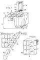
- the charger shown in Figure 1 can be viewed as comprising a bottom 10 and a basket 12 integral with each other.
- the basket is in one piece and can be viewed as having a belt 14 and cross-pieces 16 delimiting identical cells of polygonal, rectangular shape in the illustrated case, each intended to receive a cartridge 18.
- This cartridge is generally intended to disperse lures.
- the one shown in Figure 1 has an envelope 20, which can be thin although rectangular in section because it will not have to withstand the ejection pressure.
- the envelope 20 is closed by a bottom and by a cover 22. Between the bottom and the decoys is placed an unloading charge 24.
- the bottom is traversed by an electric firing primer 26 and by a fixing hole 28.
- In the belt can be embedded fixing elements such as hooks 34, often metallic.
- Figure 2 shows a first possible method of manufacturing the basket.
- a ply of fibers is folded and the two ends are connected by a seam 36, the ply being in the form of a fabric having, in addition to long bundled fibers oriented transversely to the cells, fibers directed in the direction of the arrow fO, that is to say parallel to the direction of sewing.
- the ply made tubular by the seam 36 is divided into compartments each intended to form the walls of a cell.
- cores 38 of section corresponding to that which it is desired to give to the cells.
- Elementary patterns are thus formed, comprising three cores 38 in the case illustrated in FIG. 2 (except for the angle patterns). These patterns are stacked, as indicated by the arrows f1 and then blocked against each other by winding, in the direction f2, bundles of fibers in the form of fabrics, intended to constitute the belt.
- the tissues are then subjected to a treatment intended to increase their capillarity in the direction of the arrow f0.
- the assembly is placed in a press-injection mold of thermosetting plastic, possibly after having been covered with a sheet of fibers intended to constitute the bottom of the charger, and provided with elements to be embedded in the belt.
- the mold is sealed and a mixture of resin and polymerization accelerator is injected.
- the mold is heated at least until partial hardening.
- the rack is removed from the press, the cores are extracted and the holes for fixing and access to the primers 26 are drilled in the bottom. To facilitate removal of the nuclei, a draft of the order 0.5 / 1000, tolerable without drawback for firing cartridges, is expected.
- the release is facilitated by constituting the cores in a material having a coefficient of thermal expansion significantly different from that of the composite.
- a material having a coefficient of thermal expansion significantly different from that of the composite One can in particular use light alloy cores, having undergone a surface treatment avoiding the risks of seizing, such as a surface hardening and / or having received a coating in a material with low coefficient of friction.
- a film of release material may also be provided.
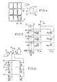
- the embodiment shown in Figure 4 generally uses bundles of fibers in two different forms. Each cell is formed by winding a braid 40 on a core 38 (only one of which is shown). Then the cores provided with the braids are stacked one on the other, with the interposition of a folded fabric 42, so that each crosspiece results from the superposition of two braids and a layer of fabric 42.
- the belt 14 is also made up with a tissue. In this case, the treatment for increasing capillarity is applied only to the fabrics intended to constitute the layers 42 and the belt 14.
- one of the firing channels is assigned not to a cell, but to the control of a multiple electrical switch making it possible to orient the other firing channels either towards the cells of a first set, or towards those of a second set.
- channel 1 controls a multiple electrical switch with three contacts 44, which can be galvanic contacts or semiconductor elements.
- An additional contact 46, also controlled by channel 1, is placed in a coding circuit 48 indicating what is the set of cells controlled.
- the electrical switch is preferably galvanic, rectilinear or rotary, and it is controlled by an actuator 50 which can be a micro-motor, an electromagnet, or even a pyrotechnic cylinder if a single operation of the actuator 50 is planned.
- an actuator 50 which can be a micro-motor, an electromagnet, or even a pyrotechnic cylinder if a single operation of the actuator 50 is planned.
- the actuator 50 controls a switch having only a play selection contact 44 and an additional contact 46.
- the contact 44 is placed on the return to ground circuit 52.
- Unidirectional conduction elements 54 such as diodes, prevent the actuation of a primer 26 other than that of the cartridge occupying the cell concerned.
Landscapes
- Engineering & Computer Science (AREA)
- General Engineering & Computer Science (AREA)
- Radar, Positioning & Navigation (AREA)
- Remote Sensing (AREA)
- Mechanical Engineering (AREA)
- Air Bags (AREA)
- Secondary Cells (AREA)
- Primary Cells (AREA)
- Toys (AREA)
- Electrostatic Charge, Transfer And Separation In Electrography (AREA)
Claims (8)
- Magazin, bestehend aus einem Boden (10) und einem Korb (12) mit einer Außenwand (14) und Zwischenwänden (16), die ein Netz von Zellen zur Aufnahme von einzelnen, jeweils mit einer Umfülladung versehenen Patronen bilden,
dadurch gekennzeichnet, daß der Korb (12) aus einem einzigen Teil aus wärmeaushärtendem Harz besteht, das mit Langfaserbündeln verstärkt ist, die in Querrichtung zur Achse der Zellen ausgerichtet ist, um dem Aufblähen der Zellen beim Schuß zu widerstehen, wobei der Fasergewichtsanteil mehr als 50 % und vorzugsweise zwischen 60 % und 70 % beträgt. - Magazin nach Anspruch 1,
dadurch gekennzeichnet, daß das Faserbündel als aneinanderhängende Fäden, als Faserbärte, als Geflechte oder als Gewebe ausgeführt ist. - Magazin nach Anspruch 1 oder 2,
dadurch gekennzeichnet, daß die Fasern aus Kohlenstoff bestehen. - Verfahren zur Herstellung eines Magazins nach einem der Ansprüche 1 bis 3,
dadurch aekennzeichnet, daß Kerne, die die Form der Zellen erzeugen, mit gebündelten, trockenen, langen Fasern beschichtet werden, die in Querrichtung zur Achse der Zellen ausgerichtet sind und jeweils zur Bildung der Wand von mehreren aneinandergrenzenden Zellen beitragen, die beschichteten Kerne aufeinandergestapelt werden, um die Netze von Zellen zu bilden, wobei die Fasern einer Behandlung zur Erhöhung der Kapillarität in axialer Richtung unterzogen werden, ein wärmeaushärtendes Harz in die Bündel eingespritzt wird und dieses polymerisiert wird, bevor die Kerne herausgenommen werden. - Verfahren nach Anspruch 4,
dadurch gekennzeichnet, daß nach dem Aufstapeln und vor dem Einspritzen die Außenwand des Korbes durch Umwickeln des Stapels beschichteter Kerne mit einem Bündel trockener Fasern gebildet wird. - Verfahren nach Anspruch 4 oder 5,
dadurch gekennzeichnet, daß zum Beschichten der Kerne eine Lage Fasern um diese herumgebogen wird, die beiden Enden der Lage mit einer Naht (36) verbunden werden, wobei die Lage in Form von Gewebe mit Fasern besteht, die parallel zur Richtung der Naht ausgerichtet sind, und die Lage durch flache Zwischennähte (39) in Abteilungen unterteilt wird, in die die aenannten Kerne eingeführt werden. - Verfahren nach Anspruch 4, 5 oder 6,
dadurch gekennzeichnet, daß den Kernen eine Rücknahme in der Größenordnung von 0,5/1000 gegeben wird. - Patronenabschußvorrichtung, die ein Magazin nach Anspruch 1, 2 oder 3 und ein Bodenstück (30), das dazu bestimmt ist, den Boden (10) des genannten Magazins aufzunehmen, umfaßt und eine Zündeinrichtung mit n Schußauslösemoglichkeiten aufweist, von denen mindestens eine der n Möqlichkeiten so angeschlossen ist, daß sie einen elektrischen Schalter (44) steuert, mit dem nach Belieben entweder der Abschuß der Patronen einer ersten Zellengruppe oder der Abschuß der Patronen einer zweiten Zellengruppe mit der gleichen Anzahl wie bei der ersten Gruppe ausgelöst werden kann.
Applications Claiming Priority (2)
| Application Number | Priority Date | Filing Date | Title |
|---|---|---|---|
| FR9001914A FR2658598B1 (fr) | 1990-02-16 | 1990-02-16 | Chargeur de tir de cartouches, procede de fabrication d'un tel chargeur et application a un lance-cartouche. |
| FR9001914 | 1990-02-16 |
Publications (2)
| Publication Number | Publication Date |
|---|---|
| EP0442822A1 EP0442822A1 (de) | 1991-08-21 |
| EP0442822B1 true EP0442822B1 (de) | 1994-12-07 |
Family
ID=9393820
Family Applications (1)
| Application Number | Title | Priority Date | Filing Date |
|---|---|---|---|
| EP91400400A Expired - Lifetime EP0442822B1 (de) | 1990-02-16 | 1991-02-15 | Magazin für Patronen, Herstellungsverfahren eines solchen Magazins und Verwendung in einer Patronenabschussvorrichtung |
Country Status (5)
| Country | Link |
|---|---|
| EP (1) | EP0442822B1 (de) |
| DE (1) | DE69105540T2 (de) |
| FR (1) | FR2658598B1 (de) |
| ID (1) | ID29175A (de) |
| NO (1) | NO174267C (de) |
Families Citing this family (5)
| Publication number | Priority date | Publication date | Assignee | Title |
|---|---|---|---|---|
| GB9301321D0 (en) * | 1993-01-23 | 1993-03-17 | Chemring Ltd | Dispenser |
| DE102004025667A1 (de) * | 2004-05-26 | 2005-12-22 | Wintermantel, Erich, Dipl.-Volksw. | Kernmaterial für Leichtbaukonstruktionen in Mehrschichtbauweise |
| FR2886003B1 (fr) * | 2005-05-20 | 2007-08-17 | Lacroix Soc E | Cartouche d'entrainement a securite simplifiee |
| CN111678378A (zh) * | 2020-04-24 | 2020-09-18 | 哈尔滨新科锐复合材料制造有限公司 | 航空用复合材料27孔弹匣 |
| US12286230B2 (en) * | 2022-10-10 | 2025-04-29 | Bae Systems Information And Electronic Systems Integration Inc. | Enhanced countermeasure dispensing system with increased payload capability |
Family Cites Families (6)
| Publication number | Priority date | Publication date | Assignee | Title |
|---|---|---|---|---|
| DE168213C (de) * | 1905-03-15 | |||
| US2900874A (en) * | 1948-09-18 | 1959-08-25 | Lockheed Aircraft Corp | Rocket launcher |
| FR1456090A (fr) * | 1965-09-02 | 1966-10-21 | Chomarat & Cie | Matériau de construction |
| FR2206805A5 (de) * | 1972-11-14 | 1974-06-07 | Matra Engins | |
| DE2928941A1 (de) * | 1979-07-18 | 1981-02-05 | Walter Dr Koecher | Verbundstoff, verfahren zu dessen herstellung und vorrichtung zur durchfuehrung des verfahrens |
| EP0314442A3 (de) * | 1987-10-28 | 1990-07-18 | WILSDON & CO. LTD | Platte mit Verbundkern |
-
1990
- 1990-02-16 FR FR9001914A patent/FR2658598B1/fr not_active Expired - Fee Related
-
1991
- 1991-02-15 NO NO910620A patent/NO174267C/no unknown
- 1991-02-15 DE DE69105540T patent/DE69105540T2/de not_active Expired - Fee Related
- 1991-02-15 EP EP91400400A patent/EP0442822B1/de not_active Expired - Lifetime
-
2000
- 2000-02-15 ID IDW00200101630A patent/ID29175A/id unknown
Also Published As
| Publication number | Publication date |
|---|---|
| FR2658598A1 (fr) | 1991-08-23 |
| DE69105540T2 (de) | 1995-04-13 |
| DE69105540D1 (de) | 1995-01-19 |
| FR2658598B1 (fr) | 1992-06-12 |
| NO174267C (no) | 1994-04-06 |
| ID29175A (id) | 2001-08-09 |
| NO910620L (no) | 1991-08-19 |
| NO174267B (no) | 1993-12-27 |
| EP0442822A1 (de) | 1991-08-21 |
| NO910620D0 (no) | 1991-02-15 |
Similar Documents
| Publication | Publication Date | Title |
|---|---|---|
| EP0442822B1 (de) | Magazin für Patronen, Herstellungsverfahren eines solchen Magazins und Verwendung in einer Patronenabschussvorrichtung | |
| EP0812674B1 (de) | Ein Herstellungsverfahren eines Gegenstandes aus faserverstärktem thermoplastischem Kunststoff, ein Stossstangenträger und eine mit diesem Träger ausgerüstete Stossstange | |
| EP2609643B1 (de) | Zweipolige batteriezelle mit optimiertem gehäuse | |
| EP3233364B1 (de) | Montageverfahren zwischen einem teil aus metallmaterial und einem teil aus organischem matrixverbundwerkstoff, entsprechende anordnung | |
| US20050197020A1 (en) | Hard armor composite | |
| JP2005513287A5 (de) | ||
| EP0544561A1 (de) | Beschussfeste Panzerung für dem Körper | |
| FR2765319A1 (fr) | Procede d'amorcage electrique et de commande de la combustion d'une charge propulsive ainsi qu'une charge propulsive obtenue | |
| FR2740380A1 (fr) | Procede de fabrication d'une pale a pas variable en materiau composite pour rotor d'helicoptere | |
| AU2018219022A1 (en) | Composite sporting equipment | |
| EP4056345A1 (de) | Verfahren zur herstellung eines behälters für die aufnahme eines unter druck stehenden gases, insbesondere von wasserstoff | |
| FR3098754A1 (fr) | Produit composite à paroi mince renforcé par des fils hybrides et procédé de fabrication d’un tel produit | |
| WO2001053772A1 (fr) | Conteneur pour munitions de gros calibre | |
| KR101729351B1 (ko) | 매거진-통합 탄약 | |
| EP0641989B1 (de) | Magazin formende Munition zum Verschiessen elektromagnetischer Düppel | |
| US6047626A (en) | Vehicle armor anchoring assembly | |
| US4221622A (en) | Method of obtaining fibre substrates intended for the production of composite bodies | |
| GB2184563A (en) | Optical fibre units | |
| BE1024439B1 (fr) | Dispositif multicouche composite d'un moule a chauffage endogene avec systeme de refroidissement force | |
| EP0881458B1 (de) | Treibladungsbehälter | |
| EP0518747B1 (de) | Elektrischer Heizwiderstand mit Elementen aus Kohlenstoff/Kohlenstoff-Kompositmaterialien | |
| EP0337952A1 (de) | Nähmaschine | |
| US6381825B1 (en) | Method for packing fibers into a case | |
| FR2609835A1 (fr) | Materiau d'etancheite et son application a l'industrie du cable | |
| EP4308755B1 (de) | Verfahren zur herstellung einer turbomaschinenkomponente aus verbundstoff mit versteifungszone |
Legal Events
| Date | Code | Title | Description |
|---|---|---|---|
| PUAI | Public reference made under article 153(3) epc to a published international application that has entered the european phase |
Free format text: ORIGINAL CODE: 0009012 |
|
| AK | Designated contracting states |
Kind code of ref document: A1 Designated state(s): DE GB IT SE |
|
| 17P | Request for examination filed |
Effective date: 19911118 |
|
| R17P | Request for examination filed (corrected) |
Effective date: 19911118 |
|
| 17Q | First examination report despatched |
Effective date: 19930504 |
|
| GRAA | (expected) grant |
Free format text: ORIGINAL CODE: 0009210 |
|
| AK | Designated contracting states |
Kind code of ref document: B1 Designated state(s): DE GB IT SE |
|
| GBT | Gb: translation of ep patent filed (gb section 77(6)(a)/1977) |
Effective date: 19941212 |
|
| REF | Corresponds to: |
Ref document number: 69105540 Country of ref document: DE Date of ref document: 19950119 |
|
| ITF | It: translation for a ep patent filed | ||
| PLBE | No opposition filed within time limit |
Free format text: ORIGINAL CODE: 0009261 |
|
| STAA | Information on the status of an ep patent application or granted ep patent |
Free format text: STATUS: NO OPPOSITION FILED WITHIN TIME LIMIT |
|
| 26N | No opposition filed | ||
| PGFP | Annual fee paid to national office [announced via postgrant information from national office to epo] |
Ref country code: GB Payment date: 19970207 Year of fee payment: 7 |
|
| PGFP | Annual fee paid to national office [announced via postgrant information from national office to epo] |
Ref country code: SE Payment date: 19970220 Year of fee payment: 7 |
|
| PG25 | Lapsed in a contracting state [announced via postgrant information from national office to epo] |
Ref country code: GB Free format text: LAPSE BECAUSE OF NON-PAYMENT OF DUE FEES Effective date: 19980215 |
|
| PG25 | Lapsed in a contracting state [announced via postgrant information from national office to epo] |
Ref country code: SE Free format text: LAPSE BECAUSE OF NON-PAYMENT OF DUE FEES Effective date: 19980216 |
|
| GBPC | Gb: european patent ceased through non-payment of renewal fee |
Effective date: 19980215 |
|
| EUG | Se: european patent has lapsed |
Ref document number: 91400400.7 |
|
| PGFP | Annual fee paid to national office [announced via postgrant information from national office to epo] |
Ref country code: DE Payment date: 20000212 Year of fee payment: 10 |
|
| PG25 | Lapsed in a contracting state [announced via postgrant information from national office to epo] |
Ref country code: DE Free format text: LAPSE BECAUSE OF NON-PAYMENT OF DUE FEES Effective date: 20011201 |
|
| PG25 | Lapsed in a contracting state [announced via postgrant information from national office to epo] |
Ref country code: IT Free format text: LAPSE BECAUSE OF NON-PAYMENT OF DUE FEES;WARNING: LAPSES OF ITALIAN PATENTS WITH EFFECTIVE DATE BEFORE 2007 MAY HAVE OCCURRED AT ANY TIME BEFORE 2007. THE CORRECT EFFECTIVE DATE MAY BE DIFFERENT FROM THE ONE RECORDED. Effective date: 20050215 |