EP0442591B1 - Multifield switchgear with a bus bar arrangement - Google Patents
Multifield switchgear with a bus bar arrangement Download PDFInfo
- Publication number
- EP0442591B1 EP0442591B1 EP91250033A EP91250033A EP0442591B1 EP 0442591 B1 EP0442591 B1 EP 0442591B1 EP 91250033 A EP91250033 A EP 91250033A EP 91250033 A EP91250033 A EP 91250033A EP 0442591 B1 EP0442591 B1 EP 0442591B1
- Authority
- EP
- European Patent Office
- Prior art keywords
- busbar
- busbars
- switchgear
- recesses
- carriers
- Prior art date
- Legal status (The legal status is an assumption and is not a legal conclusion. Google has not performed a legal analysis and makes no representation as to the accuracy of the status listed.)
- Expired - Lifetime
Links
Images
Classifications
-
- H—ELECTRICITY
- H02—GENERATION; CONVERSION OR DISTRIBUTION OF ELECTRIC POWER
- H02B—BOARDS, SUBSTATIONS OR SWITCHING ARRANGEMENTS FOR THE SUPPLY OR DISTRIBUTION OF ELECTRIC POWER
- H02B1/00—Frameworks, boards, panels, desks, casings; Details of substations or switching arrangements
- H02B1/20—Bus-bar or other wiring layouts, e.g. in cubicles, in switchyards
-
- H—ELECTRICITY
- H02—GENERATION; CONVERSION OR DISTRIBUTION OF ELECTRIC POWER
- H02G—INSTALLATION OF ELECTRIC CABLES OR LINES, OR OF COMBINED OPTICAL AND ELECTRIC CABLES OR LINES
- H02G5/00—Installations of bus-bars
- H02G5/02—Open installations
- H02G5/025—Supporting structures
Definitions
- the invention relates to an electrical switchgear assembly with a plurality of assembled fields and busbars which extend over a plurality of fields and which are arranged to run within the overall dimensions of the switchgear assembly and are held by means of insulating busbar supports.
- Switchgear of this type have become known both with busbars arranged at the top and with busbars arranged at the rear.
- Siemens "low-voltage switchgear 8PU.011" order no. A19100-E74-A91 code 174 224 PA 3865
- Insulating holders completely encompass the busbars and fix them in the directions transverse to the longitudinal extent.
- switchgear for example according to DE-A-32 43 079, has a busbar space which extends over the entire height of the field at the rear of each field. It is also known to provide a busbar compartment, which is located on the rear of the switch panels and extends only over part of the height of the panel (company publication Siemens "low-voltage switchgear 8PG" order no. E22V (1877 - code 122 051 Ps 4735 ).
- a so-called push-through method is used here, in which busbars of suitable length are inserted laterally into the busbar space.
- This process requires a free space in the assembly workshop, which corresponds to the length of the busbars. This means that double the width of the switchgear being assembled must be kept free in the workshop.
- it is already known to mount comb-like busbar holders on successive side walls of a switchgear with the opposite direction of the recesses in such a way that after a busbar has been pushed through, it can be inserted into the recesses (DE-B-1 194 027).
- the invention has for its object to simplify the assembly of busbars in multi-panel switchgear and in particular to reduce the space requirement in the manufacturing workshop.
- this object is achieved in that a fully accessible busbar space is formed by local recessed or retracted profile of the supporting elements of adjacent fields and that the busbar supports are comb-shaped with recesses for receiving the full profile of the busbars.
- This design makes the push-through method previously used and the associated space requirement unnecessary. Rather, the busbars can be inserted directly into the associated holder.
- the busbar supports are only provided with cutouts according to the profile of the busbars, the busbars are sufficiently firm, since a connection is always made with further busbars, and thus a comprehensive stiffening and fastening is achieved when the switchgear is finished.
- the width of the recesses to dimension the busbar support to the larger dimension of the profile of the busbars and to arrange the busbars assigned to the different phases one above the other. This not only reduces the depth of the busbar space and facilitates the insertion of the busbars into the busbar supports, but also reduces the forces which the currents flowing in the busbars exert on the busbars.
- busbar holders have undercut projections and in that support elements for engaging the projections of the busbar carriers are arranged.
- the recesses in the busbar support can be arranged at an angle to the rear wall of the switchgear. This measure can improve the safe position of the busbars until they are connected to other busbars.
- the invention further provides a device for mounting busbars on a switchgear with a rear busbar compartment in such a way that the device has at least two holders provided with cutouts corresponding to the cutouts of the busbar supports, and that clamping devices are provided for temporarily fastening the busbars in the holders are.
- busbars can be mounted on the holders in a convenient working position. After fastening the busbars in their holders, the devices can be removed and used again.
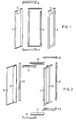
- Figure 1 shows schematically in perspective the main components of the scaffolding of a low-voltage switchgear with overhead busbar compartment.
- FIG. 2 shows the main components of a low-voltage switchgear assembly with a rear busbar compartment in a representation corresponding to FIG.
- FIG. 3 shows an overhead busbar holder
- FIG. 4 shows a switchgear schematically with a view of a busbar compartment arranged on the rear.
- FIG. 5 shows an assembly device for inserting busbars into busbar supports according to FIG. 4.
- FIG. 6 shows a busbar support with obliquely arranged recesses for busbars.
- FIG. 1 the essential parts of a field of a low-voltage switchgear are shown in perspective.
- a left side wall 1 and a right side wall 2 each have a profile indentation 3 or 4 at their upper end, which delimits an upwardly open busbar space.
- a back wall 5 and an upper cross member 6 and a lower cross member 7 complete the scaffolding arrangement. Because all side walls 1 and 2 are provided with profile indentations 3 and 4, a busbar space that is accessible along the entire length is created in a multi-field system. This enables continuous busbars to be inserted without the previous push-through method. In this way, the busbars simultaneously engage the recesses of all the busbar supports provided.
- a switchgear with parts according to Figure 2 is particularly suitable for the case that a larger busbar space is required to control a higher rated current.
- side walls 10 and 11 are provided with a rear profile indentation 12 and 13, respectively, which extend over the major part of the height dimension of the side walls 10 and 11.
- Upper cross pieces 14, 15 and lower cross pieces 16, 17 determine the width of a field of the switchgear.
- Rear vertical end profiles 20 (left) and 21 (right) and associated end cross pieces 22 (top) and 23 (bottom) form support surfaces for a rear wall, which can be attached after mounting the busbar assembly.
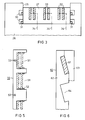
- FIG. 3 shows schematically in section an overhead busbar compartment of a switchgear.
- a cutout is formed by cutouts 25 in the successive side walls 26 of the adjacent panels, in which a continuous busbar pull can be arranged for all adjacent panels.
- Busbar supports 27 are provided which engage with hook-like lateral extensions 30 via holding members 31.
- Busbars 33 are inserted into recesses 32 in busbar support 27. The depth of the recesses 32 corresponds to the height of the rectangular profile of the busbar.
- Two busbar conductors 33 are assigned to one phase. An upper cover or fastening of the busbar conductors is not necessary, because the connection of the busbar conductors 33 to further and multiple fastening busbars ensures a sufficiently rigid fastening.
- Such further busbars 34 are indicated by dashed lines in FIG. 3.
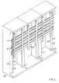
- FIG. 4 shows a switchgear consisting of three fields placed side by side with a view of a busbar space 18 provided on the rear.
- the fields consist of parts corresponding to FIG. 2, the reference numerals of which are also entered in FIG.
- the fields on the back have a profile indentation, which by the Shape of the side walls 10 and 11 is effected.
- the profile indentations 12 and 13 of the side walls 10 and 11 are formed by bent legs 35 and 36, the ends of which are again provided with a bent leg 37 and 38, respectively, towards the rear of the switchgear.
- the legs 35 and 37 or 36 and 38 serve to attach busbar holders 40, which consist of a lower part 41 and a mirror-image upper part 42. Two busbar holders 40 are provided for each field.
- a busbar space provided on the rear of the switch panels is particularly suitable for busbar trains with a large cross section.
- four busbars 43 are arranged per phase, specifically two busbars 43 in parallel and two such parallel pairs one above the other.
- the upper parts 41 and the lower parts 42 of the busbar holders 40 extend over the entire height of the busbar arrangement.
- a mounting device 50 according to FIG. 5 is provided for mounting the busbars 43. This is designed like a fork and has recesses 51 for receiving the busbars 43. To temporarily hold the busbars 43, the mounting device 50 is provided with suitable latching devices, for example with elements 52 similar to ball catches. 5, the assembly device 50 is shown broken off. Two recesses 51 are shown for two busbars each, i. H. for a total of four busbars 43, which form a phase in the arrangement according to FIG. Holes 53 shape the mounting device 50.
- mounting devices 50 are first attached in a suitable number to the side walls 10 and 11 (FIG. 4), e.g. B. by means of the holes 53 provided in the mounting devices 50. Then the busbars are inserted into the recesses 51, the busbars come into alignment with corresponding recesses in the lower parts 41 of the busbar holder 40. As soon as all busbars 43 are inserted, the upper parts 42 can be placed on and firmly connected to the lower parts 41 to form the complete busbar holder 40. The assembly devices 50 can now be removed and used again.
- a busbar support 60 is shown broken off, which is also provided for use in connection with a busbar space arranged on the rear.
- the busbar support 60 serves to receive busbars 61 and is designed for this purpose in such a way that the lower part 62 and the upper part 63 can be fitted together in a matching manner.
- Recesses 64 corresponding to the profile of the busbars 61 are arranged in the lower part 62 and are inclined backwards in such a way that a stable position is provided when the busbars 61 are inserted into the cutouts 64. It is therefore not necessary to temporarily fasten the busbars 61.
- busbars 61 Only after all the busbars 61 provided have been inserted into the associated recesses 64 is the upper part 63 placed on and connected to the lower part 62 in a suitable manner.
- a busbar 61 is shown between the lower part 62 and the upper part 63.
- the upper part 63 is omitted, so that the shape of the recess 64 of the lower part 62 can be seen better.
Abstract
Description
Die Erfindung betrifft eine elektrische Schaltanlage mit mehreren zusammengesetzten Feldern und sich über mehrere Felder erstreckenden Sammelschienen, die innerhalb der Gesamtabmessungen der Schaltanlage verlaufend angeordnet und mittels isolierender Sammelschienenträger gehalten sind.The invention relates to an electrical switchgear assembly with a plurality of assembled fields and busbars which extend over a plurality of fields and which are arranged to run within the overall dimensions of the switchgear assembly and are held by means of insulating busbar supports.
Schaltanlagen dieser Art sind sowohl mit obenliegend angeordneten Sammelschienen als auch mit rückseitig angeordneten Sammelschienen bekannt geworden. Beispielsweise ist in der Firmendruckschrift Siemens "Niederspannungs-Schaltanlage 8PU.011" (Bestell-Nr. A19100-E74-A91-Kennzeichen 174 224 PA 3865) eine Bauweise beschrieben, bei welcher der obere Bereich jedes Feldes der Schaltanlage gegenüber dem Einbauraum der Geräte durch eine Zwischenwand abgetrennt und zur Aufnahme von Sammelschienen vorgesehen ist. Isolierende Halter umgreifen die Sammelschienen vollständig und legen sie in den Richtungen quer zur Längserstreckung fest.Switchgear of this type have become known both with busbars arranged at the top and with busbars arranged at the rear. For example, in the company brochure Siemens "low-voltage switchgear 8PU.011" (order no. A19100-E74-A91 code 174 224 PA 3865), a construction is described in which the upper area of each field of the switchgear compared to the installation space of the devices an intermediate wall is separated and is provided for receiving busbars. Insulating holders completely encompass the busbars and fix them in the directions transverse to the longitudinal extent.
Eine andere Bauweise einer Schaltanlage etwa gemäß der DE-A-32 43 079 weist einen Sammelschienenraum auf, der sich an der Rückseite jedes Feldes über die gesamte Höhe des Feldes erstreckt. Ferner ist es bekannt, einen Sammelschienenraum vorzusehen, der sich an der Rückseite der Schaltfelder befindet und sich nur über einen Teil der Höhe des Feldes erstreckt (Firmendruckschrift Siemens "Niederspannungs-Schaltanlagen 8PG" Bestell-Nr. E22V(1877 - Kennzeichen 122 051 Ps 4735).Another construction of a switchgear, for example according to DE-A-32 43 079, has a busbar space which extends over the entire height of the field at the rear of each field. It is also known to provide a busbar compartment, which is located on the rear of the switch panels and extends only over part of the height of the panel (company publication Siemens "low-voltage switchgear 8PG" order no. E22V (1877 - code 122 051 Ps 4735 ).
Sowohl mit Rücksicht auf die Betriebssicherheit als auch zur Verringerung der Anzahl von Bearbeitungs- und Montagevorgängen ist es erwünscht, die Sammelschienen in möglichst großer Länge zusammenhängend für eine mehrfeldrige Schaltanlage zu montieren.With regard to operational safety as well as to reduce the number of machining and assembly processes, it is desirable to assemble the busbars in the greatest possible length for a multi-panel switchgear.
Hierbei wird ein sog. Durchschiebeverfahren angewandt, bei dem Sammelschienen geeigneter Länge seitlich in den Sammelschienenraum eingeführt werden. Dieser Vorgang erfordert in der Montagewerkstatt einen freien Raum, welcher der Länge der Sammelschienen entspricht. Somit muß in der Werkstatt die doppelte Breite der in der Montage befindlichen Schaltanlage freigehalten werden. Um diesen Vorgang zu erleichtern, ist es bereits bekannt, kammartige Sammelschienenhalter an aufeinanderfolgenden Seitenwänden einer Schaltanlage mit entgegengesetzter Richtung der Ausnehmungen derart anzubringen, daß nach dem Durchstecken einer Sammelschiene diese in die Ausnehmungen eingelegt werden kann (DE-B-1 194 027).A so-called push-through method is used here, in which busbars of suitable length are inserted laterally into the busbar space. This process requires a free space in the assembly workshop, which corresponds to the length of the busbars. This means that double the width of the switchgear being assembled must be kept free in the workshop. In order to facilitate this process, it is already known to mount comb-like busbar holders on successive side walls of a switchgear with the opposite direction of the recesses in such a way that after a busbar has been pushed through, it can be inserted into the recesses (DE-B-1 194 027).
Der Erfindung liegt die Aufgabe zugrunde, die Montage von Sammelschienen bei mehrfeldrigen Schaltanlagen zu vereinfachen und insbesondere den Raumbedarf in der Fertigungswerkstatt zu verringern.The invention has for its object to simplify the assembly of busbars in multi-panel switchgear and in particular to reduce the space requirement in the manufacturing workshop.
Gemäß der Erfindung wird diese Aufgabe dadurch gelöst, daß durch örtliche zurückgesetztes bzw. eingezogenen Profil der tragenden Elemente benachbarter Felder ein auf ganzer Länge zugänglicher Sammelschienenraum gebildet ist und daß die Sammelschienenträger kammartig mit Ausnehmungen zur Aufnahme des vollen Profils der Sammelschienen ausgebildet sind. Diese Gestaltung macht das bisher gebräuchliche Durchschiebeverfahren und den hiermit verbundenen Raumbedarf entbehrlich. Vielmehr lassen sich die Sammelschienen direkt in die zugehörigen Halter einlegen. Obwohl die Sammelschienenträger lediglich mit Ausschnitten entsprechend dem Profil der Sammelschienen versehen sind, liegen die Sammelschienen ausreichend fest, da stets eine Verbindung mit weiterführenden Stromschienen hergestellt wird, und damit bei fertiggestellter Schaltanlage eine umfassende Versteifung und Befestigung erzielt wird.According to the invention, this object is achieved in that a fully accessible busbar space is formed by local recessed or retracted profile of the supporting elements of adjacent fields and that the busbar supports are comb-shaped with recesses for receiving the full profile of the busbars. This design makes the push-through method previously used and the associated space requirement unnecessary. Rather, the busbars can be inserted directly into the associated holder. Although the busbar supports are only provided with cutouts according to the profile of the busbars, the busbars are sufficiently firm, since a connection is always made with further busbars, and thus a comprehensive stiffening and fastening is achieved when the switchgear is finished.
Wird der Sammelschienenraum an der Rückseite der Schaltanlage vorgesehen, so empfiehlt es sich, die Breite der Ausnehmungen der Sammelschienenträger der größeren Abmessung des Profils der Sammelschienen entsprechend zu bemessen und die den unterschiedlichen Phasen zugeordneten Sammelschienen übereinander anzuordnen. Hierdurch wird nicht nur die Tiefe des Sammelschienenraumes verringert und das Einlegen der Sammelschienen in die Sammelschienenträger erleichtert, sondern es werden auch die Käfte verringert, welche die in den Sammelschienen fließenden Ströme auf die Sammelschienen ausüben.If the busbar compartment is provided on the rear of the switchgear, it is recommended to use the width of the recesses to dimension the busbar support to the larger dimension of the profile of the busbars and to arrange the busbars assigned to the different phases one above the other. This not only reduces the depth of the busbar space and facilitates the insertion of the busbars into the busbar supports, but also reduces the forces which the currents flowing in the busbars exert on the busbars.
Eine weitere Vereinfachung der Montage der Sammelschienen ist dadurch zu erzielen, daß die Sammelschienenhalter hinterschnittene Vorsprünge aufweisen und daß Tragelemente zum Eingreifen der Vorsprünge der Sammelschienenträger angeordnet sind.A further simplification of the assembly of the busbars can be achieved in that the busbar holders have undercut projections and in that support elements for engaging the projections of the busbar carriers are arranged.
Ferner können bei rückseitiger Anordnung des Sammelschienenraumes die Ausnehmungen der Sammelschienenträger winklig zur Rückwand der Schaltanlage angeordnet sein. Diese Maßnahme vermag die sichere Lage der Sammelschienen bis zu ihrer Verbindung mit weiteren Stromschienen zu verbessern.Furthermore, with the rear arrangement of the busbar space, the recesses in the busbar support can be arranged at an angle to the rear wall of the switchgear. This measure can improve the safe position of the busbars until they are connected to other busbars.
Die Erfindung sieht ferner eine Vorrichtung zur Montage von Sammelschienen an einer Schaltanlage mit rückseitig angeordnetem Sammelschienenraum in der Ausführung vor, daß die Vorrichtung wenigstens zwei mit Ausschnitten entsprechend den Ausschnitten der Sammelschienenträger versehene Halter aufweist, und daß Klemmvorrichtungen zur vorübergehenden Befestigung der Sammelschienen in den Haltern vorgesehen sind. Auf diese Weise können Sammelschienen in einer bequemen Arbeitsstellung an den Haltern montiert werden. Nach der Befestigung der Sammelschienen in ihren Haltern können die Vorrichtungen abgenommen und erneut benutzen werden.The invention further provides a device for mounting busbars on a switchgear with a rear busbar compartment in such a way that the device has at least two holders provided with cutouts corresponding to the cutouts of the busbar supports, and that clamping devices are provided for temporarily fastening the busbars in the holders are. In this way, busbars can be mounted on the holders in a convenient working position. After fastening the busbars in their holders, the devices can be removed and used again.
Die Erfindung wird im folgenden anhand der in den Figuren dargestellten Ausführungsbeispiele näher erläutert.The invention is explained in more detail below with reference to the exemplary embodiments shown in the figures.
Die Figur 1 zeigt schematisch in perspektivischer Darstellung die Hauptbestandtteile des Gerüstes einer Niederspannungs-Schaltanlage mit obenliegendem Sammelschienenraum.Figure 1 shows schematically in perspective the main components of the scaffolding of a low-voltage switchgear with overhead busbar compartment.
In der Figur 2 sind in einer der Figur 1 entsprechenden Darstellung die Hauptbestandtteile eine Niederspannungs-Schaltanlage mit rückseitig angeordnetem Sammelschienenraum gezeigt.FIG. 2 shows the main components of a low-voltage switchgear assembly with a rear busbar compartment in a representation corresponding to FIG.
Die Figur 3 zeigt einen obenliegenden Sammelschienenhalter.FIG. 3 shows an overhead busbar holder.
In der Figur 4 ist eine Schaltanlage schematisch mit Blick auf einen rückseitig angeordneten Sammelschienenraum.4 shows a switchgear schematically with a view of a busbar compartment arranged on the rear.
Die Figur 5 zeigt eine Montagevorrichtung zum Einsetzen von Sammelschienen in Sammelschienenträger gemäß der Figur 4.FIG. 5 shows an assembly device for inserting busbars into busbar supports according to FIG. 4.
In der Figur 6 ist ein Sammelschienenträger mit schräg angeordneten Ausnehmungen für Sammelschienen gezeigt.FIG. 6 shows a busbar support with obliquely arranged recesses for busbars.
In der Figur 1 sind die wesentlichen Teile eines Feldes einer Niederspannungs-Schaltanlage auseinander gezogen perspektivisch dargestellt. Eine linke Seitenwand 1 und eine rechte Seitenwand 2 weisen an ihrem oberen Ende jeweils eine Profileinziehung 3 bzw. 4 auf, die einen nach oben offenen Sammelschienenraum begrenzt. Eine Rückwand 5 sowie ein oberer Querholm 6 und ein unterer Querholm 7 vervollständigen die Gerüstanordnung. Dadurch, daß alle Seitenwände 1 und 2 mit Profileinziehungen 3 bzw. 4 versehen sind, entsteht bei einer mehrfeldrigen Anlage ein auf der ganzen Länge zugänglicher Sammelschienenraum. Dies ermöglicht das Einlegen durchgehende Sammelschienen ohne das bisherige Durchschiebeverfahren. Die Sammelschienen gelangen auf diese Weise gleichzeitig in Eingriff mit den Ausnehmungen aller vorgesehener Sammelschienenträger.In Figure 1, the essential parts of a field of a low-voltage switchgear are shown in perspective. A left side wall 1 and a
Eine Schaltanlage mit Teilen gemäß der Figur 2 ist besonders für den Fall geeignet, daß ein größerer Sammelschienenraum benötigt wird, um einen höheren Nennstrom zu beherrschen. Wie die Figur 2 zeigt, sind Seitenwände 10 und 11 mit einer rückwärtigen Profileinziehung 12 bzw. 13 versehen, die sich über den überwiegenden Teil der Höhenabmessung der Seitenwände 10 und 11 erstrecken. Obere Querstücke 14, 15 sowie untere Querstücke 16, 17 bestimmen die Breite eines Feldes der Schaltanlage. Rückseitige vertikale Abschlußprofile 20 (links) bzw. 21 (rechts) und zugehörige Abschlußquerstücke 22 (oben) und 23 (unten) bilden Auflageflächen für eine Rückwand, die nach der Montage der Sammelschienenanordnung angebracht werden kann.A switchgear with parts according to Figure 2 is particularly suitable for the case that a larger busbar space is required to control a higher rated current. As FIG. 2 shows,
Die Figur 3 zeigt schematisch im Schnitt einen obenliegend angeordneten Sammelschienenraum einer Schaltanlage. Durch Aussparungen 25 in den aufeinanderfolgenden Seitenwänden 26 der benachbarten Felder wird eine Profileinziehung gebildet, in welcher ein durchgehender Sammelschienenzug für alle benachbarten Schaltfelder angeordnet werden kann. Es sind Sammelschienenträger 27 vorgesehen, die mit hakenartigen seitlichen Fortsätzen 30 über Halteorgane 31 greifen. In Ausnehmungen 32 der Sammelschienenträger 27 sind Sammelschienen 33 eingelegt. Die Tiefe der Ausnehmungen 32 entspricht dabei der Höhe des Rechteckprofils der Sammelschienenleiter. Je zwei Sammelschienenleiter 33 sind einer Phase zugeordnet. Eine obere Abdeckung oder Befestigung der Sammelschienenleiter ist nicht erforderlich, weil durch die Verbindung der Sammelschienenleiter 33 mit weiterführenden und mehrfach befestigten Stromschienen eine ausreichend starre Befestigung gewährleistet ist. Solche weiterführenden Stromschienen 34 sind in der Figur 3 gestrichelt angedeutet.Figure 3 shows schematically in section an overhead busbar compartment of a switchgear. A cutout is formed by
Die Figur 4 zeigt eine aus drei nebeneinander aufgestellten Feldern bestehende Schaltanlage mit Blick auf einen rückseitig vorgesehenen Sammelschienenraum 18. Die Felder bestehen aus der Figur 2 entsprechenden Teilen, deren Bezugszeichen auch in der Figur 4 eingetragen sind. Wie man erkennt, weisen die Felder rückseitig eine Profileinziehung auf, welche durch die Gestalt der Seitenwände 10 und 11 bewirkt ist. Die Profileinziehungen 12 bzw. 13 der Seitenwände 10 und 11 sind durch abgekantete Schenkel 35 bzw. 36 gebildet, deren Enden nochmals, und zwar in Richtung zur Rückseite der Schaltanlage, mit einem abgekanteten Schenkel 37 bzw. 38 versehen sind. Die Schenkel 35 und 37 bzw. 36 und 38 dienen zur Anbringung von Sammelschienenhaltern 40, die aus einem Unterteil 41 und einem spiegelbildlichen Oberteil 42 bestehen. Je Feld sind zwei Sammelschienenhalter 40 vorgesehen.FIG. 4 shows a switchgear consisting of three fields placed side by side with a view of a
Wie bereits erwähnt, eignet sich ein rückseitig an den Schaltfeldern vorgesehener Sammelschienenraum insbesondere für Sammelschienenzüge mit großem Querschnitt. In dem in der Figur 4 gezeigten Beispiel sind je Phase vier Sammelschienen 43 angeordnet, und zwar jeweils zwei Schienen 43 parallel und zwei solcher paralleler Paare übereinander. Die Oberteile 41 und die Unterteile 42 der Sammelschienenhalter 40 erstrecken sich über die gesamte Höhe der Sammelschienenanordnung.As already mentioned, a busbar space provided on the rear of the switch panels is particularly suitable for busbar trains with a large cross section. In the example shown in FIG. 4, four
Zur Montage der Sammelschienen 43 ist eine Montagevorrichtung 50 gemäß der Figur 5 vorgesehen. Diese ist gabelartig gestaltet und weist Ausnehmungen 51 zur Aufnahme der Sammelschienen 43 auf. Zu vorübergehenden Halterung der Sammelschienen 43 ist die Montagevorrichtung 50 mit geeigneten Rastvorrichtungen, beispielsweise mit Elementen 52 ähnlich Kugelschnappern versehen. In der Figur 5 ist die Montagevorrichtung 50 abgebrochen dargestellt. Gezeigt sind zwei Ausnehmungen 51 für je zwei Sammelschienen, d. h. für die insgesamt vier Sammelschienen 43, die in der Anordnung gemäß der Figur 4 eine Phase bilden. Löcher 53 gestalten die Befestigung der Montagevorrichtung 50.A
Zur Montage der Sammelschienen werden zunächst Montagevorrichtungen 50 in einer geeigneten Anzahl an den Seitenwänden 10 und 11 (Figur 4) befestigt, z. B. mittels der in den Montagevorrichtungen 50 vorgesehenen Löcher 53. Dann werden die Sammelschienen in die Ausnehmungen 51 eingelegt, wobei die Sammelschienen in eine fluchtende Stellung zu entsprechenden Ausnehmungen der Unterteile 41 der Sammelschienenhalter 40 gelangen. Sobald alle Sammelschienen 43 eingelegt sind, können die Oberteile 42 aufgelegt und fest mit den Unterteilen 41 zur Bildung der kompletten Sammelschienenhalter 40 verbunden werden. Die Montagevorrichtungen 50 können nun abgenommen und erneut verwendet werden.To assemble the busbars, mounting
In der Figur 6 ist abgebrochen ein Sammelschienenträger 60 gezeigt, der gleichfalls zur Verwendung in Verbindung mit einem rückseitig angeordneten Sammelschienenraum vorgesehen ist. Der Sammelschienenträger 60 dient zur Aufnahme von Sammelschienen 61 und ist hierzu derart gestaltet, daß das Unterteil 62 und das Oberteil 63 zusammenpassend zusammenfügbar sind. In dem Unterteil 62 sind dem Profil der Sammelschienen 61 entsprechende Ausnehmungen 64 angeordnet, die derart rückwärts geneigt sind, daß beim Einlegen der Sammelschienen 61 in die Ausnehmungen 64 eine stabile Lage gegeben ist. Es bedarf daher keiner vorübergehenden Befestigung der Sammelschienen 61. Erst nachdem alle vorgesehenen Sammelschienen 61 in die zugehörigen Ausnehmungen 64 eingelegt sind, wird das Oberteil 63 aufgelegt und in geeigneter Weise mit dem Unterteil 62 verbunden. Im oberen Teil der Figur 6 ist eine Sammelschiene 61 zwischen dem Unterteil 62 und dem Oberteil 63 gezeigt. Im unteren Teil der Figur 6 ist das Oberteil 63 fortgelassen, so daß die Gestalt der Ausnehmung 64 des Unterteiles 62 besser erkennbar ist.In FIG. 6, a
Vorstehend ist die Erfindung im Zusammenhang mit einer Sammelschienenanordnung erläutert, die jeweils mehrere Sammelschienen je Phase aufweist. Wie ohne weiteres aus der vorangehenden Beschreibung ersichtlich ist, eignet sich jedoch die neue Gestaltung einer Schaltanlage und die hierzu erläuterte Montagevorrichtung gleichermaßen für Einzelsammelschienen je Phase und auch für Anordnungen mit einer größeren Anzahl von Sammelschienen je Phase.The invention has been explained above in connection with a busbar arrangement which in each case has a plurality of busbars per phase. As is readily apparent from the preceding description, however, the new design of a switchgear and the mounting device explained for this purpose are equally suitable for individual busbars per phase and also for arrangements with a larger number of busbars per phase.
Claims (5)
- Electrical switchgear having several combined sections and busbars (27) extending over several sections, which busbars are arranged so that they run within the over-all dimensions of the switchgear and are retained by means of insulating busbar carriers (25), characterised in that a busbar compartment (18) accessible over its entire length is formed by a locally set back and/or indented profile (profile recesses 3, 4; 12, 13) of the carrying elements (1, 2; 10, 11) of adjacent sections and in that the busbar carriers (25; 40) are formed in the manner of a comb with recesses (26) for receiving the entire profile of the busbars (43).
- Switchgear according to claim 1, characterised in that, in the case of a busbar compartment (18) arranged on the rear side of the switchgear, the width of the recesses of the busbar carriers (40) is adjusted to correspond to the larger dimension of the profile of the busbars (43) and in that the busbars (43) assigned to different phases are arranged one above another.
- Switchgear according to claim 1 or 2, characterised in that the busbar carriers (27) have undercut projections (30) and in that carrying elements (30) (sic) are arranged for engaging with the projections (30) of the busbar carriers (27).
- Switchgear according to one of the preceding claims, characterised in that, in the case of an arrangement of the busbar compartment (18) on the rear side, the recesses (64) of the busbar carriers (60) are provided at an angle to the rear wall of the switchgear.
- Mounting apparatus for mounting busbars on a switchgear having a busbar compartment arranged on the rear side according to claim 2, characterised in that the mounting apparatus (50) at least has recesses (51) corresponding to the recesses of the busbar carriers (40), and in that clamping or catching devices (52) are provided in the recesses (51) for the temporary attachment of the busbars (43).
Applications Claiming Priority (2)
| Application Number | Priority Date | Filing Date | Title |
|---|---|---|---|
| DE4005069A DE4005069A1 (en) | 1990-02-14 | 1990-02-14 | MULTIPLE AREA SWITCHGEAR WITH A BUSBAR ARRANGEMENT |
| DE4005069 | 1990-02-14 |
Publications (3)
| Publication Number | Publication Date |
|---|---|
| EP0442591A2 EP0442591A2 (en) | 1991-08-21 |
| EP0442591A3 EP0442591A3 (en) | 1991-10-02 |
| EP0442591B1 true EP0442591B1 (en) | 1994-06-22 |
Family
ID=6400421
Family Applications (1)
| Application Number | Title | Priority Date | Filing Date |
|---|---|---|---|
| EP91250033A Expired - Lifetime EP0442591B1 (en) | 1990-02-14 | 1991-02-07 | Multifield switchgear with a bus bar arrangement |
Country Status (12)
| Country | Link |
|---|---|
| EP (1) | EP0442591B1 (en) |
| AT (1) | ATE107802T1 (en) |
| AU (1) | AU7103291A (en) |
| BR (1) | BR9100577A (en) |
| CA (1) | CA2036215A1 (en) |
| DE (2) | DE4005069A1 (en) |
| DK (1) | DK0442591T3 (en) |
| ES (1) | ES2057743T3 (en) |
| FI (1) | FI910704A (en) |
| NO (1) | NO178389C (en) |
| PT (1) | PT96752B (en) |
| RU (1) | RU2036543C1 (en) |
Cited By (1)
| Publication number | Priority date | Publication date | Assignee | Title |
|---|---|---|---|---|
| DE19738705A1 (en) * | 1997-08-29 | 1999-03-04 | Siemens Ag | Distribution system of energy technology with one device insert |
Families Citing this family (10)
| Publication number | Priority date | Publication date | Assignee | Title |
|---|---|---|---|---|
| DE4328241A1 (en) * | 1993-08-19 | 1995-02-23 | Siemens Ag | Multi-panel switchgear with an arc barrier |
| SE516600C2 (en) * | 1996-05-14 | 2002-02-05 | Maarten Hansson | Device for nested coupling equipment for installation on floors |
| DE19816589C1 (en) * | 1998-04-08 | 2000-01-20 | Siemens Ag | Multi-panel switchgear with a busbar arrangement |
| DE19953561C1 (en) * | 1999-11-03 | 2001-09-06 | Siemens Ag | Busbar arrangement for an electrical control panel |
| DE10014214B4 (en) * | 2000-03-17 | 2009-05-07 | Greiner Schaltanlagen Gmbh | A bus bar connector |
| DE10014216B4 (en) * | 2000-03-17 | 2009-05-07 | Greiner Schaltanlagen Gmbh | Busbar support arrangement |
| DE102007012079B4 (en) * | 2007-03-13 | 2011-07-14 | ADC GmbH, 14167 | Distribution cabinet with several inner housings |
| DE102012110247A1 (en) * | 2012-10-26 | 2014-04-30 | Eaton Industries (Austria) Gmbh | Switch cabinet with improved possibility for stringing together |
| DE102013106889A1 (en) * | 2013-07-01 | 2015-01-08 | Conductix-Wampfler Gmbh | Insulating profile, conductor rail and method for producing a conductor rail |
| EP2999073B1 (en) * | 2014-09-18 | 2017-04-19 | CBW S.r.l. | Spacer for a junction block for busbars and junction block comprising said spacer |
Family Cites Families (5)
| Publication number | Priority date | Publication date | Assignee | Title |
|---|---|---|---|---|
| US2445463A (en) * | 1944-05-30 | 1948-07-20 | Westinghouse Electric Corp | Universal bus-bar support |
| DE1194027B (en) | 1959-08-01 | 1965-06-03 | Continental Elektro Ind Ag | Bracket for busbars of switch cells |
| DE2717134C2 (en) * | 1977-04-19 | 1981-10-08 | Licentia Patent-Verwaltungs-Gmbh, 6000 Frankfurt | Arrangement for defining at least one busbar |
| DE3243079A1 (en) | 1982-11-22 | 1984-05-24 | BBC Aktiengesellschaft Brown, Boveri & Cie., Baden, Aargau | Switchgear cabinet |
| IT8722166A0 (en) * | 1987-10-06 | 1987-10-06 | Carlo Apostolo | ELECTRICAL PANEL WITH REMOVABLE DRAWERS, MODULAR AND COMPOSABLE, FOR THE CONTROL OF ELECTRIC MOTORS. |
-
1990
- 1990-02-14 DE DE4005069A patent/DE4005069A1/en not_active Withdrawn
-
1991
- 1991-02-07 DE DE59101962T patent/DE59101962D1/en not_active Expired - Fee Related
- 1991-02-07 DK DK91250033.7T patent/DK0442591T3/en active
- 1991-02-07 AT AT91250033T patent/ATE107802T1/en not_active IP Right Cessation
- 1991-02-07 ES ES91250033T patent/ES2057743T3/en not_active Expired - Lifetime
- 1991-02-07 EP EP91250033A patent/EP0442591B1/en not_active Expired - Lifetime
- 1991-02-08 BR BR919100577A patent/BR9100577A/en unknown
- 1991-02-12 CA CA002036215A patent/CA2036215A1/en not_active Abandoned
- 1991-02-13 RU SU914894487A patent/RU2036543C1/en active
- 1991-02-13 AU AU71032/91A patent/AU7103291A/en not_active Abandoned
- 1991-02-13 NO NO910584A patent/NO178389C/en unknown
- 1991-02-13 FI FI910704A patent/FI910704A/en not_active Application Discontinuation
- 1991-02-13 PT PT96752A patent/PT96752B/en not_active IP Right Cessation
Cited By (1)
| Publication number | Priority date | Publication date | Assignee | Title |
|---|---|---|---|---|
| DE19738705A1 (en) * | 1997-08-29 | 1999-03-04 | Siemens Ag | Distribution system of energy technology with one device insert |
Also Published As
| Publication number | Publication date |
|---|---|
| BR9100577A (en) | 1991-10-29 |
| EP0442591A3 (en) | 1991-10-02 |
| CA2036215A1 (en) | 1991-08-15 |
| NO910584D0 (en) | 1991-02-13 |
| FI910704A0 (en) | 1991-02-13 |
| DE59101962D1 (en) | 1994-07-28 |
| DE4005069A1 (en) | 1991-09-19 |
| ATE107802T1 (en) | 1994-07-15 |
| EP0442591A2 (en) | 1991-08-21 |
| PT96752B (en) | 1998-08-31 |
| NO178389B (en) | 1995-12-04 |
| ES2057743T3 (en) | 1994-10-16 |
| DK0442591T3 (en) | 1994-10-31 |
| RU2036543C1 (en) | 1995-05-27 |
| PT96752A (en) | 1992-12-31 |
| NO910584L (en) | 1991-08-15 |
| FI910704A (en) | 1991-08-15 |
| AU7103291A (en) | 1991-08-15 |
| NO178389C (en) | 1996-03-13 |
Similar Documents
| Publication | Publication Date | Title |
|---|---|---|
| DE2809852C2 (en) | Busbar system of a high-voltage electrical switching device | |
| EP0872000B1 (en) | Busbar channel system of a low-voltage switch equipment | |
| DE19953561C1 (en) | Busbar arrangement for an electrical control panel | |
| EP0442591B1 (en) | Multifield switchgear with a bus bar arrangement | |
| DE69932764T2 (en) | Customizable outgoing module of a low-voltage switch cell | |
| DE1640150A1 (en) | Prefabricated electrical switchgear | |
| DE2330166C3 (en) | Kit for quick assembly of switch and control panels | |
| DE4013223C2 (en) | Power supply terminal | |
| WO2007033946A1 (en) | Busbar system for electrical switchgear | |
| EP0762583A2 (en) | Low voltage bus bar system | |
| EP1619766B1 (en) | Busbar system for a low voltage switch cabinet | |
| EP0610710B1 (en) | Device for detachable fixing electric installation apparatus | |
| EP0621668B1 (en) | Protection against accidental contact for busbars | |
| DE19755690C2 (en) | switch cabinet | |
| DE2733895C2 (en) | Installation device for inserting a module | |
| WO2007033948A1 (en) | Busbar arrangement for an electrical switchgear assembly | |
| WO2008003680A1 (en) | Conductor rail holder and power distribution unit with a conductor rail holder | |
| DE2639640A1 (en) | ELECTRIC BUSBAR ARRANGEMENT | |
| DE69838156T2 (en) | Electronic power distribution device | |
| DE1640516B2 (en) | NH fuse base with a load-bearing connection rail | |
| EP0748014B1 (en) | Device for step-wise arrangement of switchgear | |
| WO2005032229A2 (en) | Base frame of a distributor | |
| DE3542747A1 (en) | DISCONNECTING ARRANGEMENTS FOR SWITCHING DEVICES SITUALLY ARRANGED AT LEADERSHIPS | |
| EP0311952A2 (en) | Bus bar support | |
| DE10024780B4 (en) | Connection arrangement of at least two functional inserts of electrical installation devices for flush mounting |
Legal Events
| Date | Code | Title | Description |
|---|---|---|---|
| PUAI | Public reference made under article 153(3) epc to a published international application that has entered the european phase |
Free format text: ORIGINAL CODE: 0009012 |
|
| PUAL | Search report despatched |
Free format text: ORIGINAL CODE: 0009013 |
|
| AK | Designated contracting states |
Kind code of ref document: A2 Designated state(s): AT BE CH DE DK ES FR GB GR IT LI LU NL SE |
|
| AK | Designated contracting states |
Kind code of ref document: A3 Designated state(s): AT BE CH DE DK ES FR GB GR IT LI LU NL SE |
|
| 17P | Request for examination filed |
Effective date: 19911029 |
|
| 17Q | First examination report despatched |
Effective date: 19930910 |
|
| GRAA | (expected) grant |
Free format text: ORIGINAL CODE: 0009210 |
|
| AK | Designated contracting states |
Kind code of ref document: B1 Designated state(s): AT BE CH DE DK ES FR GB GR IT LI LU NL SE |
|
| REF | Corresponds to: |
Ref document number: 107802 Country of ref document: AT Date of ref document: 19940715 Kind code of ref document: T |
|
| REF | Corresponds to: |
Ref document number: 59101962 Country of ref document: DE Date of ref document: 19940728 |
|
| ITF | It: translation for a ep patent filed |
Owner name: STUDIO JAUMANN |
|
| REG | Reference to a national code |
Ref country code: ES Ref legal event code: FG2A Ref document number: 2057743 Country of ref document: ES Kind code of ref document: T3 |
|
| GBT | Gb: translation of ep patent filed (gb section 77(6)(a)/1977) |
Effective date: 19940927 |
|
| ET | Fr: translation filed | ||
| REG | Reference to a national code |
Ref country code: DK Ref legal event code: T3 Ref country code: GR Ref legal event code: FG4A Free format text: 3013112 |
|
| EAL | Se: european patent in force in sweden |
Ref document number: 91250033.7 |
|
| PGFP | Annual fee paid to national office [announced via postgrant information from national office to epo] |
Ref country code: DK Payment date: 19950217 Year of fee payment: 5 |
|
| PGFP | Annual fee paid to national office [announced via postgrant information from national office to epo] |
Ref country code: SE Payment date: 19950227 Year of fee payment: 5 Ref country code: FR Payment date: 19950227 Year of fee payment: 5 |
|
| PGFP | Annual fee paid to national office [announced via postgrant information from national office to epo] |
Ref country code: NL Payment date: 19950228 Year of fee payment: 5 Ref country code: BE Payment date: 19950228 Year of fee payment: 5 |
|
| PGFP | Annual fee paid to national office [announced via postgrant information from national office to epo] |
Ref country code: DE Payment date: 19950419 Year of fee payment: 5 |
|
| PLBE | No opposition filed within time limit |
Free format text: ORIGINAL CODE: 0009261 |
|
| STAA | Information on the status of an ep patent application or granted ep patent |
Free format text: STATUS: NO OPPOSITION FILED WITHIN TIME LIMIT |
|
| PGFP | Annual fee paid to national office [announced via postgrant information from national office to epo] |
Ref country code: CH Payment date: 19950517 Year of fee payment: 5 |
|
| 26N | No opposition filed | ||
| PGFP | Annual fee paid to national office [announced via postgrant information from national office to epo] |
Ref country code: GB Payment date: 19960122 Year of fee payment: 6 |
|
| PGFP | Annual fee paid to national office [announced via postgrant information from national office to epo] |
Ref country code: AT Payment date: 19960124 Year of fee payment: 6 |
|
| PGFP | Annual fee paid to national office [announced via postgrant information from national office to epo] |
Ref country code: GR Payment date: 19960131 Year of fee payment: 6 |
|
| PGFP | Annual fee paid to national office [announced via postgrant information from national office to epo] |
Ref country code: LU Payment date: 19960201 Year of fee payment: 6 |
|
| PG25 | Lapsed in a contracting state [announced via postgrant information from national office to epo] |
Ref country code: DK Effective date: 19960207 |
|
| REG | Reference to a national code |
Ref country code: DK Ref legal event code: EBP |
|
| PG25 | Lapsed in a contracting state [announced via postgrant information from national office to epo] |
Ref country code: SE Effective date: 19960208 |
|
| PGFP | Annual fee paid to national office [announced via postgrant information from national office to epo] |
Ref country code: ES Payment date: 19960216 Year of fee payment: 6 |
|
| PG25 | Lapsed in a contracting state [announced via postgrant information from national office to epo] |
Ref country code: LI Free format text: LAPSE BECAUSE OF NON-PAYMENT OF DUE FEES Effective date: 19960228 Ref country code: CH Free format text: LAPSE BECAUSE OF NON-PAYMENT OF DUE FEES Effective date: 19960228 Ref country code: BE Effective date: 19960228 |
|
| BERE | Be: lapsed |
Owner name: SIEMENS A.G. Effective date: 19960228 |
|
| PG25 | Lapsed in a contracting state [announced via postgrant information from national office to epo] |
Ref country code: NL Effective date: 19960901 |
|
| REG | Reference to a national code |
Ref country code: CH Ref legal event code: PL |
|
| PG25 | Lapsed in a contracting state [announced via postgrant information from national office to epo] |
Ref country code: FR Effective date: 19961031 |
|
| NLV4 | Nl: lapsed or anulled due to non-payment of the annual fee |
Effective date: 19960901 |
|
| PG25 | Lapsed in a contracting state [announced via postgrant information from national office to epo] |
Ref country code: DE Effective date: 19961101 |
|
| REG | Reference to a national code |
Ref country code: FR Ref legal event code: ST |
|
| PG25 | Lapsed in a contracting state [announced via postgrant information from national office to epo] |
Ref country code: LU Free format text: LAPSE BECAUSE OF NON-PAYMENT OF DUE FEES Effective date: 19970207 Ref country code: GB Effective date: 19970207 Ref country code: AT Effective date: 19970207 |
|
| PG25 | Lapsed in a contracting state [announced via postgrant information from national office to epo] |
Ref country code: ES Free format text: LAPSE BECAUSE OF NON-PAYMENT OF DUE FEES Effective date: 19970208 |
|
| PG25 | Lapsed in a contracting state [announced via postgrant information from national office to epo] |
Ref country code: GR Free format text: THE PATENT HAS BEEN ANNULLED BY A DECISION OF A NATIONAL AUTHORITY Effective date: 19970831 |
|
| GBPC | Gb: european patent ceased through non-payment of renewal fee |
Effective date: 19970207 |
|
| REG | Reference to a national code |
Ref country code: GR Ref legal event code: MM2A Free format text: 3013112 |
|
| REG | Reference to a national code |
Ref country code: ES Ref legal event code: FD2A Effective date: 19990405 |
|
| PG25 | Lapsed in a contracting state [announced via postgrant information from national office to epo] |
Ref country code: IT Free format text: LAPSE BECAUSE OF NON-PAYMENT OF DUE FEES;WARNING: LAPSES OF ITALIAN PATENTS WITH EFFECTIVE DATE BEFORE 2007 MAY HAVE OCCURRED AT ANY TIME BEFORE 2007. THE CORRECT EFFECTIVE DATE MAY BE DIFFERENT FROM THE ONE RECORDED. Effective date: 20050207 |