EP0442310B1 - Nippel bestimmt zum Zusammenwirken mit mehreren Kupplungsbestandteilen - Google Patents
Nippel bestimmt zum Zusammenwirken mit mehreren Kupplungsbestandteilen Download PDFInfo
- Publication number
- EP0442310B1 EP0442310B1 EP91101006A EP91101006A EP0442310B1 EP 0442310 B1 EP0442310 B1 EP 0442310B1 EP 91101006 A EP91101006 A EP 91101006A EP 91101006 A EP91101006 A EP 91101006A EP 0442310 B1 EP0442310 B1 EP 0442310B1
- Authority
- EP
- European Patent Office
- Prior art keywords
- nipple
- longitudinally extending
- cylindrical member
- hollow cylindrical
- extending hollow
- Prior art date
- Legal status (The legal status is an assumption and is not a legal conclusion. Google has not performed a legal analysis and makes no representation as to the accuracy of the status listed.)
- Expired - Lifetime
Links
- 210000002445 nipple Anatomy 0.000 title claims description 100
- 230000008878 coupling Effects 0.000 title claims description 93
- 238000010168 coupling process Methods 0.000 title claims description 93
- 238000005859 coupling reaction Methods 0.000 title claims description 93
- 239000011324 bead Substances 0.000 claims description 15
- 238000007789 sealing Methods 0.000 claims description 8
- 238000009792 diffusion process Methods 0.000 claims description 6
- 238000001914 filtration Methods 0.000 claims description 6
- 238000012856 packing Methods 0.000 description 3
- 230000002093 peripheral effect Effects 0.000 description 2
- 238000000502 dialysis Methods 0.000 description 1
- 239000000385 dialysis solution Substances 0.000 description 1
- 239000012530 fluid Substances 0.000 description 1
- 238000002615 hemofiltration Methods 0.000 description 1
- 239000000463 material Substances 0.000 description 1
Images


Classifications
-
- F—MECHANICAL ENGINEERING; LIGHTING; HEATING; WEAPONS; BLASTING
- F16—ENGINEERING ELEMENTS AND UNITS; GENERAL MEASURES FOR PRODUCING AND MAINTAINING EFFECTIVE FUNCTIONING OF MACHINES OR INSTALLATIONS; THERMAL INSULATION IN GENERAL
- F16L—PIPES; JOINTS OR FITTINGS FOR PIPES; SUPPORTS FOR PIPES, CABLES OR PROTECTIVE TUBING; MEANS FOR THERMAL INSULATION IN GENERAL
- F16L25/00—Construction or details of pipe joints not provided for in, or of interest apart from, groups F16L13/00 - F16L23/00
- F16L25/009—Combination of a quick-acting type coupling and a conventional one
-
- A—HUMAN NECESSITIES
- A61—MEDICAL OR VETERINARY SCIENCE; HYGIENE
- A61M—DEVICES FOR INTRODUCING MEDIA INTO, OR ONTO, THE BODY; DEVICES FOR TRANSDUCING BODY MEDIA OR FOR TAKING MEDIA FROM THE BODY; DEVICES FOR PRODUCING OR ENDING SLEEP OR STUPOR
- A61M39/00—Tubes, tube connectors, tube couplings, valves, access sites or the like, specially adapted for medical use
- A61M39/10—Tube connectors; Tube couplings
- A61M2039/1033—Swivel nut connectors, e.g. threaded connectors, bayonet-connectors
-
- A—HUMAN NECESSITIES
- A61—MEDICAL OR VETERINARY SCIENCE; HYGIENE
- A61M—DEVICES FOR INTRODUCING MEDIA INTO, OR ONTO, THE BODY; DEVICES FOR TRANSDUCING BODY MEDIA OR FOR TAKING MEDIA FROM THE BODY; DEVICES FOR PRODUCING OR ENDING SLEEP OR STUPOR
- A61M39/00—Tubes, tube connectors, tube couplings, valves, access sites or the like, specially adapted for medical use
- A61M39/10—Tube connectors; Tube couplings
- A61M2039/1083—Tube connectors; Tube couplings having a plurality of female connectors, e.g. Luer connectors
-
- A—HUMAN NECESSITIES
- A61—MEDICAL OR VETERINARY SCIENCE; HYGIENE
- A61M—DEVICES FOR INTRODUCING MEDIA INTO, OR ONTO, THE BODY; DEVICES FOR TRANSDUCING BODY MEDIA OR FOR TAKING MEDIA FROM THE BODY; DEVICES FOR PRODUCING OR ENDING SLEEP OR STUPOR
- A61M39/00—Tubes, tube connectors, tube couplings, valves, access sites or the like, specially adapted for medical use
- A61M39/10—Tube connectors; Tube couplings
- A61M2039/1088—Tube connectors; Tube couplings having a plurality of male connectors, e.g. Luer connectors
Definitions
- the present invention relates to a nipple, and in particular, a nipple which is intended to form part of a so-called Hansen coupling. More particularly, the present invention relates to nipples intended for use with Hansen couplings in which one coupling component comprises the nipple which includes at least one recess on its outer peripheral surface while the other coupling component has a sleeve-like portion, which is capable of being telescopically pushed over the nipple, and which includes a locking means, such as balls, which are engaged in the recess on the outer surface of the nipple.
- the present invention relates to nipples which are intended to form part of a dialyzer or similar diffusion and/or filtration device. Still more particularly, the present invention relates to such nipples which are intended for use in such apparatus so as to render it possible to couple same to different tube systems, which can include coupling components intended either for throw-away use or which are intended for multiple utilization. Alternatively, the present invention is also directed to such nipples which can form part of a tube coupling for the coupling together of two tubular components.
- Hansen couplings there are a number of different examples of Hansen couplings, such as those shown in U.S. Patent Nos. 2,518,542; 3,351,362 and 4,198,080 (& DE-A-2913302). As is evident from the sheer number of these patents, this type of coupling has been in use for a rather long period of time.
- These Hansen-type couplings consist, on the one side, of a nipple, and on the other side of a sleeve-like portion which is capable of being telescopically pushed over the nipple.
- the sleeve-like portion of the coupling exists in various forms including both simple and somewhat more complicated variants.
- the other coupling component i e the nipples themselves, may, for example, form a part of a dialyzer, and thus be coupled normally by means of conventional Hansen couplings to tubes originating from a conventional diaysis monitor. If it is desired to use this same housing provided with such nipples in connection with hemofiltration, for example, the nipples must then be coupled to a tube set which is intended for throw-away use. Because of the concomitant high cost, such an arrangement can not comprise conventional Hansen couplings, but must instead make use of simpler couplings, such as simple threaded plastic components and the like.
- a nipple which can be used for coupling to a plurality of secondary coupling components
- the nipple comprising a longitudinally extending hollow cylindrical member having an outer surface, an inner surface, an inner end, and an outer end, said outer end being intended to face anyone of said secondary coupling components, with the outer surface of the longitudinally extending hollow cylindrical member including an outer recess adapted for engagement with a Hansen-type secondary coupling component, including locking means for engaging the outer recess.
- the nipple according to the present invention is characterized in that it includes thread means located between the outer recess and the outer end of the longitudinally extending hollow cylindrical member, the thread means being adapted for engagement with a threaded secondary coupling component including corresponding threads thereon.
- the nipple in accordance with this invention is thus adapted so that it can form part of a so-called Hansen coupling, and thus includes a nipple with one or more recesses on its outer peripheral surface so that it can couple with a secondary coupling component having a sleeve-like part capable of being telescopically pushed over the nipple and which is provided on its inside with locking means such as balls which can engage in the recess or recesses of the nipple, and which is further characterized by a thread arranged either on the inside or the outside of the nipple and situated between the outer end of the nipple and the recess or recesses, and which is suitable for coupling together with other coupling components provided with a matching thread therefor.
- the recess on the outer surface of the nipple preferably constitutes a circular groove around the entire periphery of the nipple, the groove being separated from the outer end of the nipple by a raised cylindrical portion.
- This groove can be replaced by one or more recesses of different shapes and sizes.
- the thread means are located on the outer surface of the longitudinally extending hollow cylindrical member.
- the thread means are located on the inner surface of the longitudinally extending hollow cylindrical member.
- that member also includes a raised cylindrical portion located between the annular groove and the outer end of the longitudinally extending hollow cylindrical member.
- the raised cylindrical portion is adapted to serve as a sealing surface with respect to at least one of the plurality of secondary coupling components.
- the nipple includes a chamfered surface located between the raised cylindrical portion and the outer end of the longitudinally extending hollow cylindrical member, the chamfered surface being adapted to act as a seal with respect to at least one of the plurality of secondary coupling components.
- either the raised cylindrical portion itself can be adapted to serve as a sealing surface upon coupling, or it can be finished off on the outside by an inwardly chamfered sealing surface which is adapted to either seal against the other coupling component or against a packing or other seal provided therein.
- the raised cylindrical portion has a first diameter
- the outer end of the longitudinally extending hollow cylindrical member includes an end cylindrical portion having a second diameter, with the second diameter being less than the first diameter
- the thread means are preferably dimensioned such that the threads are not engageable with the locking means of the Hansen-type secondary coupling component.
- the nipple is preferably designed such that the locking means in the Hansen-type secondary coupling component to which it is to be coupled cannot fall down in locking position into the thread, but can only do so with the recess or recesses specifically adapted therefor.
- 4,198,080 can be obtained with its ridges extending axially to the nipple, i.e., so that a reduced build-up of material in the otherwise thickened portion of the nipple can be utilized without any risk of an incorrect locking position being created.
- the thread means has a predetermined depth so as to provide an internal thread diameter for the thread means, and the second diameter of the end cylindrical portion is less than that internal thread diameter.
- nipple includes the aforementioned end cylindrical portion which is narrower than the raised cylindrical portion, and these two portions are further separated by a chamfered surface whose original height is preferably slightly higher than the depth of the threads.
- the thread means comprise a plurality of axially extending bead components which are adapted to interact with an internal valve in the Hansen-type secondary coupling component.
- this plurality of bead components comprise three such bead components evenly distributed about the inner surface of the longitudinally extending hollow cylindrical member.
- the threads are thus arranged in a number of axially extending ridges or beads which are inwardly directed and which, in connection with a standard Hansen coupling, are intended to open an inner valve in that other coupling component.
- An acceptable thread can be achieved if these ridges or grooves are three in number and are evenly distributed about the periphery of the inner, otherwise cylindrical surface of the nipple.
- the end cylindrical portion having a reduced diameter is adapted to sealingly cooperate with a sealing bead directed inwardly from the second coupling component.
- the nipple can itself be provided with a sealing bead, which is adapted to seal against a smooth cylindrical sealing surface facing inwardly from the other coupling component,
- the seal can be further improved if the threads are adapted to extend in towards the recess or recesses but without reaching same.
- these thread means are separated from the outer recess on the outer surface of the longitudinally extending hollow cylindrical member.
- an apparatus for diffusion or filtration is provided with at least one nipple extending outwardly from a cylindrical housing, the nipple being adapted for use in coupling the apparatus to a plurality of secondary coupling components, and the nipple including a longitudinally extending hollow cylindrical member having an inner surface, an outer surface, an inner end and an outer end, said outer end being intended to face anyone of said secondary components, and the outer surface of the longitudinally extending hollow cylindrical member including an outer recess adapted for engagement with a Hansen-type secondary coupling component including locking means for engaging said outer recess.
- the apparatus according to the present invention is characterized in that said nipple includes thread means located between the recess and the outer end of the longitudinally extending hollow cylindrical member and being adapted for engagement with a threaded secondary coupling component including corresponding threads thereon.
- the present invention relates to application of such a nipple in a manner such that the nipple can be used to couple a dialyzer or similar diffusion and/or filtration device to different tube systems which can include coupling components intended either for throw-away use or of the type which are intended for multiple use.
- FIGS. 1 and 4 in which like reference numerals refer to like portions thereof, it is first noted that the specific designs shown in FIGS. 1 and 4 will be referred to, for purposes of clarity, simply as dialyzers.
- FIG. 1 shows a dialyzer 1 consisting of a casing 2 having two end closure parts 3, and with an inlet 4 and an outlet 5 for the dialyzed fluid. If the design shown in FIG. 1 is used solely for dialysis, dialysis fluid is supplied and withdrawn through two nipples 6.
- Nipple 6 is shown on a larger scale in FIG. 1a.
- Nipple 6 is provided about its periphery with a recess 7 having chamfered walls 8 and 9.
- the outer end of the nipple is designated by reference numeral 10.
- a raised cylindrical portion 11 As is customary on nipples which are used for conventional Hansen couplings. This is finished off towards the outer end 10 thereof by a chamfered surface 12, which is separated from the outer end 10 by a lowered or reduced diameter cylindrical portion 13.
- the nipple 6 is provided with a thread 14 on the raised cylindrical portion 11.
- FIG. 2A there is shown a coupling component 15, which is standard for a conventional Hansen coupling, and is adapted to be coupled to the nipple 6 shown in FIG. 1A.
- the coupling component 15 is provided with locking means 16 acting inwardly, in this case being balls which are intended to engage in the groove 7 in the nipple 6 upon coupling.
- the balls 16 are controlled in a conventional manner, by means of guide ring 17 arranged between a spring 18 and a lock ring 19.
- the coupling component shown also comprises a packing 20.
- FIGS. 2B, 2C and 2D thee are shown three further coupling components 15b, 15c and 15d, respectively, each of which is provided with an internal thread 14' matching thread 14.
- the coupling components according to FIGS. 2B and 2C are also provided with a packing, 20b and 20c, respectively.
- each of the coupling components in accordance with FIGS. 2A through 2D fit the nipple 6, and can be sealingly coupled thereto.
- the specific seal in accordance with the design according to FIG. 3D is brought about by means of a sealing bead 23, which is specifically shown in the enlarged circular section thereof shown in this Figure.
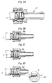
- FIGS. 4 through 6D correspond in principle to those according to FIGS. 1 through 3D. Corresponding parts, therefore, have been given the same reference numerals. The difference in these cases lie in the fact that the external thread 14 in FIG. 1A, for example, has been replaced by an internal thread, which is designated by reference numeral 21 in FIG. 4A. In the same manner, the internal thread 14' in FIGS. 2B though 2D is replaced by an external thread 21' in FIGS. 5B through 5D.
- the internal thread 21 may be continuous, as shown schematically in FIG. 4A. Preferably, however, it is broken up, and presented by a number of axially extending ridges 22, as shown in FIG. 7.
- each of the coupling components according to FIGS. 5A through 5D fit the nipple 6, as shown in FIG. 4A. A further detailed description of FIGS. 4 through 7 is therefore not required.
- the present invention is not limited solely to the examples of embodiments described above, but can be varied within the framework of the following claims.
- the groove 7 in the nipple 6 may be given many different designs, either as one recess or as a number of recesses.
Landscapes
- Engineering & Computer Science (AREA)
- Health & Medical Sciences (AREA)
- Heart & Thoracic Surgery (AREA)
- General Engineering & Computer Science (AREA)
- Animal Behavior & Ethology (AREA)
- Veterinary Medicine (AREA)
- Anesthesiology (AREA)
- Biomedical Technology (AREA)
- Hematology (AREA)
- Life Sciences & Earth Sciences (AREA)
- Mechanical Engineering (AREA)
- General Health & Medical Sciences (AREA)
- Public Health (AREA)
- Pulmonology (AREA)
- Quick-Acting Or Multi-Walled Pipe Joints (AREA)
- External Artificial Organs (AREA)
- Prostheses (AREA)
- Branch Pipes, Bends, And The Like (AREA)
- Separation Using Semi-Permeable Membranes (AREA)
- Insulating Bodies (AREA)
- Respiratory Apparatuses And Protective Means (AREA)
- Details Of Connecting Devices For Male And Female Coupling (AREA)
Claims (20)
- Nippel (6) für die Benutzung beim Kuppeln an mehrere Sekundärkupplungsbestandteile (15, 15b, 15c, 15d), wobei der Nippel (6) ein sich längs erstreckendes, hohles, zylindrisches Teil aufweist mit einer inneren Oberfläche, einer äußeren Oberfläche, einem inneren Ende und einem äußeren Ende, wobei das äußere Ende dazu bestimmt ist, zu einem beliebigen Sekundärkupplungsbestandteil (15, 15b, 15c, 15d) gerichtet zu sein, die äußere Oberfläche des sich längs erstreckenden, hohlen, zylindrischen Teiles eine äußere Ausnehmung (7) aufweist, die geeignet angepaßt ist für den Eingriff mit einem Sekundärkupplungsbestandteil (15) nach dem Hansen-Typ, einschließlich Verriegelungsmitteln (16) für den Eingriff mit der äußeren Ausnehmung (7), dadurch gekennzeichnet, daß der Nippel (6) Gewindemittel (14, 21) aufweist, die zwischen der äußeren Ausnehmung (7) und dem äußeren Ende des sich längs erstreckenden, hohlen, zylindrischen Teils angeordnet sind und die Gewindemittel (14, 21) angepaßt sind für den Eingriff mit einem mit Gewinde versehenen Sekundärkupplungsbestandteil (15b, 15c, 15d), einschließlich entsprechenden Gewinden (14', 21') auf diesem.
- Nippel nach Anspruch 1, wobei die Gewindemittel (14) auf der äußeren Oberfläche des sich längs erstreckenden, hohlen, zylindrischen Teils angeordnet sind.
- Nippel nach Anspruch 1, wobei die Gewindemittel (21) auf der inneren Oberfläche des sich längs erstreckenden, hohlen, zylindrischen Teils angeordnet sind.
- Nippel nach Anspruch 1, wobei die äußere Ausnehmung (7) eine ringförmige Nut aufweist, die sich über den gesamten äußeren Umfang des sich längs erstreckenden, hohlen, zylindrischen Teils erstreckt.
- Nippel nach Anspruch 4, wobei die Gewindemittel (14) auf der äußeren Oberfläche des sich längs erstreckenden, hohlen, zylindrischen Teils angeordnet sind und das sich längs erstreckende, hohle, zylindrische Teil ein erhabenes, zylindrisches Teik (11) aufweist, weiches zwischen der ringförmigen Nut oder Ausnehmung (7) und dem äußeren Ende des sich längs erstreckenden, hohlen, zylindrischen Teils angeordnet ist.
- Nippel nach Anspruch 5, wobei das erhabene zylindrische Teil (11) angepaßt ist, um als eine Dichtoberfläche bezüglich mindestens eines der Mehrzahl von Sekundärkupplungsbestandteilen (15, 15b, 15c, 15d) zu dienen.
- Nippel nach Anspruch 5 mit einer abgeschrägten Oberfläche (12), die zwischen dem erhabenen, zylindrischen Teil (11) und dem äußeren Ende des sich längs erstreckenden, hohlen, zylindrischen Teils angeordnet ist, wobei die abgeschrägte Oberfläche (12) derart angepaßt ist, daß sie als eine Dichtung bezüglich mindestens einem (15, 15c) der Mehrzahl von Sekundärkupplungsbestandteilen wirkt.
- Nippel nach Anspruch 7, wobei das erhabene zylindrische Teil (11) einen ersten Durchmesser hat und das äußere Ende des sich längs erstreckenden, zylindrischen Teils einen endzylindrischen Teil (13) mit einem zweiten Durchmesser aufweist, weicher kleiner als der erste Durchmesser ist.
- Nippel nach Anspruch 2, wobei das Gewindemittel (14) derart bemessen ist, daß die Gewindemittel (14) nicht mit den Verriegelungsmitteln (16) des Sekundärkunpplungsbestandteiles (15) nach dem Hansen-Typ in Eingriff bringbar sind.
- Nippel nach Anspruch 8, wobei das Gewindemittel (14) eine vorbestimmte Tiefe hat, um einen Innengewindedurchmesser für das Gewindemittel (14) vorzusehen und wobei der zweite Durchmesser kleiner ist als der Innengewindedurchmesser.
- Nippel nach Anspruch 3, wobei das Gewindemittel (21) eine Mehrzahl von sich axial erstreckenden Wulstbestandteilen (22) aufweist, die derart angepaßt sind, daß sie mit einem Innenventil in dem Sekundärkupplungsbestandteil (15) nach dem Hansen-Typ in Wechselwirkung stehen.
- Nippel nach Anspruch 11, wobei die Vielzahl von Wulstbestandteilen drei solche Wulstbestandteile (22) aufweist, die gleichmäßig über die innere Oberfläche des sich längs erstreckenden, hohlen, zylindrischen Teils verteilt sind.
- Nippel nach Anspruch 1, wobei das Gewindemittel (14) von der äußeren Ausnehmung (7) auf der äußeren Oberfläche des sich längs erstreckenden, hohlen, zylindrischen Teils getrennt ist.
- Vorrichtung für die Diffusion oder Filtration mit mindestens einem Nippel (6), der sich von einem zylindrischen Gehäuse nach außen erstreckt, wobei der Nippel (6) angepaßt ist für die Benutzung beim Ankuppeln der Vorrichtung an eine Mehrzahl von Sekundärkupplungsbestandteilen (15, 15b, 15c, 15d), wobei der Nippel (6) ein sich längs erstreckendes, hohles, zylindrisches Teil aufweist mit einer inneren Oberfläche, einer äußeren Oberfläche, einem inneren Ende und einem äußeren Ende, wobei das äußere Ende dazu bestimmt ist, zu einem beliebigen der Sekundärkupplungsbestandteile (15, 15b, 15c, 15d) gerichtet zu sein, und wobei die äußere Oberfläche des sich längs erstreckenden, hohlen, zylindrischen Teils eine äußere Ausnehmung (7) aufweist, die geeignet ist für den Eingriff mit einem Sekundärkupplungsbestandteil (15) nach dem Hansen-Typ, einschließlich Verriegelungsmitteln (16) für den Eingriff mit der äußeren Ausnehmung (7), dadurch gekennzeichnet, daß der Nippel (6) Gewindemittel (14, 21) aufweist, die zwischen der Ausnehmung (7) und dem äußeren Ende des sich längs erstreckenden, hohlen, zylindrischen Teils angeordnet sind und angepaßt sind für den Eingriff mit einem mit Gewinde versehenen Sekundärkupplungsbestandteil (15b, 15c, 15d), einschließlich entsprechenden Gewinden (14', 21').
- Vorrichtung nach Anspruch 14, wobei die Gewindemittel (14) auf der äußeren Oberfläche des sich längs erstreckenden, hohlen, zylindrischen Teils angeordnet sind.
- Vorrichtung nach Anspruch 14, wobei die Gewindemittel (21) auf der inneren Oberfläche des sich längs erstreckenden, hohlen, zylindrischen Teils angeordnet sind.
- Vorrichtung nach Anspruch 14, wobei die äußere Ausnehmung (7) eine ringförmige Nut aufweist, die sich über den ganzen äußeren Umfang des sich längs erstreckenden, hohlen, zylindrischen Teils erstreckt.
- Vorrichtung nach Anspruch 17, wobei die Gewindemittel (14) auf der äußeren Oberfläche des sich längs erstreckenden, hohlen, zylindrischen Teils angeordnet sind und wobei das sich längs erstreckende, hohle, zylindrische Teil ein erhabenes, zylindrisches Teil (11) aufweist, welches zwischen der ringförmigen Nut oder Ausnehmung (7) und dem äußeren Ende des sich längs erstreckenden, hohlen, zylindrischen Teils angeordnet ist.
- Vorrichtung nach Anspruch 16, wobei das Gewindemittel (21) eine Mehrzahl von sich axial erstreckenden Wulstbestandteilen (22) aufweist, die geeignet angepaßt sind, um mit einem Innenventil in dem Sekundärkupplungsbestandteil (15) nach dem Hansen-Typ in Wechselwirkung zu stehen.
- Vorrichtung nach Anspruch 19, wobei die Mehrzahl von Wulstbestandteilen (22) drei solcher Wulstbestandteile aufweist, die über der inneren Oberfläche des sich längs erstreckenden, hohlen, zylindrischen Teils gleichmäßig verteilt sind.
Applications Claiming Priority (2)
| Application Number | Priority Date | Filing Date | Title |
|---|---|---|---|
| SE9000541A SE466813B (sv) | 1990-02-15 | 1990-02-15 | Anvaendning av en nippel, som aer avsedd att bilda en del av en s k hansen-koppling |
| SE9000541 | 1990-08-21 |
Publications (2)
| Publication Number | Publication Date |
|---|---|
| EP0442310A1 EP0442310A1 (de) | 1991-08-21 |
| EP0442310B1 true EP0442310B1 (de) | 1993-08-25 |
Family
ID=20378569
Family Applications (1)
| Application Number | Title | Priority Date | Filing Date |
|---|---|---|---|
| EP91101006A Expired - Lifetime EP0442310B1 (de) | 1990-02-15 | 1991-01-26 | Nippel bestimmt zum Zusammenwirken mit mehreren Kupplungsbestandteilen |
Country Status (7)
| Country | Link |
|---|---|
| US (1) | US5165728A (de) |
| EP (1) | EP0442310B1 (de) |
| JP (1) | JP3452589B2 (de) |
| DE (1) | DE69100283T2 (de) |
| DK (1) | DK0442310T3 (de) |
| ES (1) | ES2043395T3 (de) |
| SE (1) | SE466813B (de) |
Families Citing this family (27)
| Publication number | Priority date | Publication date | Assignee | Title |
|---|---|---|---|---|
| SE502103C2 (sv) * | 1991-08-01 | 1995-08-14 | Gambro Dialysatoren | Filterenhet för överföring av massa och/eller värme innehållande hålrumsfibrer |
| US5335943A (en) * | 1993-04-20 | 1994-08-09 | Duane Duryea | Automobile engine hose system with plurality of adaptor members |
| US5772624A (en) * | 1995-07-20 | 1998-06-30 | Medisystems Technology Corporation | Reusable blood lines |
| US5613484A (en) * | 1996-02-07 | 1997-03-25 | Golden Key Futura, Inc. | Archery bow and connector-stabilizer assembly and improved connector-stabilizer sub-assembly for the same |
| US5845943A (en) * | 1996-12-02 | 1998-12-08 | Colder Products Company | Hybrid insert for fluid couplings |
| US5896889A (en) * | 1997-10-24 | 1999-04-27 | Menard; Orville R. | Quick-set hydraulic coupler |
| US6824415B2 (en) * | 2001-11-01 | 2004-11-30 | Andrew Corporation | Coaxial connector with spring loaded coupling mechanism |
| DE10352859B3 (de) * | 2003-11-10 | 2005-06-02 | Fresenius Medical Care Deutschland Gmbh | Konnektor für Dialysatorport |
| US7762279B2 (en) | 2005-11-05 | 2010-07-27 | Snap-Tite Technologies, Inc. | Threaded coupling with flow shutoff |
| US7575024B2 (en) | 2005-11-05 | 2009-08-18 | Snap-Tite Technologies, Inc. | Threaded coupling with flow shutoff |
| US8257286B2 (en) * | 2006-09-21 | 2012-09-04 | Tyco Healthcare Group Lp | Safety connector apparatus |
| US7985068B2 (en) * | 2007-05-04 | 2011-07-26 | Irwin Industrial Tool Company | Gas appliance |
| US7987754B2 (en) | 2007-07-31 | 2011-08-02 | Newell Window Furnishings, Inc. | Window covering sizing method and apparatus |
| US8257287B2 (en) * | 2008-03-20 | 2012-09-04 | Tyco Healthcare Group Lp | Safety connector assembly |
| US20090276989A1 (en) * | 2008-05-06 | 2009-11-12 | Halia Accessories Inc. | Strand Locking Mechanism Assembly |
| DE102008027676A1 (de) * | 2008-06-03 | 2009-12-10 | Karl Storz Gmbh & Co. Kg | Kupplung für ein medizinisches Instrument |
| IT1390600B1 (it) * | 2008-07-08 | 2011-09-09 | Sit La Precisa Spa Con Socio Unico | Sistema di connessione a tenuta di gruppi valvolari con rispettive tubazioni, in particolare nell'impiego con gas combustibili |
| IN2011KN04777A (de) * | 2009-04-23 | 2015-07-10 | Fresenius Medical Care De Gmbh | |
| EP2688602B1 (de) | 2011-03-23 | 2019-11-06 | NxStage Medical, Inc. | Peritonealdialysesysteme, -vorrichtungen und -verfahren |
| US9597475B2 (en) * | 2011-07-15 | 2017-03-21 | Jack C McPhearson | Fast connect device for oxygen humidity bottles and other medical containers |
| HK1199851A1 (en) | 2011-09-21 | 2015-07-24 | Bayer Healthcare Llc | Continuous multi-fluid pump device, drive and actuating system and method |
| HRP20250654T1 (hr) | 2015-01-09 | 2025-07-18 | Bayer Healthcare Llc | Višestruki sustav za isporuku tekućine s višenamjenskim jednokratnim kompletom i njegove značajke |
| WO2018237375A1 (en) | 2017-06-24 | 2018-12-27 | Nxstage Medical, Inc. | Peritoneal dialysis fluid preparation and/or treatment devices methods and systems |
| CA3092575A1 (en) | 2018-02-28 | 2019-09-06 | Nxstage Medical, Inc. | Fluid preparation and treatment devices, methods, and systems |
| WO2021069586A1 (en) * | 2019-10-09 | 2021-04-15 | Stobbe Pharma Gmbh | Simplified fluid connection and membrane filter |
| DE102020111867A1 (de) | 2020-04-30 | 2021-11-04 | Fresenius Medical Care Deutschland Gmbh | Hämodialysevorrichtung mit Gasaustauscher |
| CN116421315B (zh) * | 2023-06-14 | 2023-09-05 | 中南大学 | 一种连接装置及手术导航系统 |
Family Cites Families (13)
| Publication number | Priority date | Publication date | Assignee | Title |
|---|---|---|---|---|
| US2518542A (en) * | 1948-07-21 | 1950-08-15 | Fred E Hansen | Steam hose coupling |
| US3351362A (en) * | 1965-04-19 | 1967-11-07 | Hansen Mfg Co | Quick-disconnective coupling |
| US3473782A (en) * | 1966-11-23 | 1969-10-21 | John D Gessic | Coupling device |
| US3863958A (en) * | 1973-05-02 | 1975-02-04 | William H Todd | Universal hose coupling |
| IT1086546B (it) * | 1977-05-23 | 1985-05-28 | Uniflex Spa | Giunto per tubi flessibili ad aggancio e sgancio rapido |
| US4198080A (en) * | 1978-05-19 | 1980-04-15 | Baxter Travenol Laboratories, Inc. | Telescoping-type connector |
| US4366945A (en) * | 1978-12-20 | 1983-01-04 | Abnox Ag | Hose coupling with double lock |
| SE8204648D0 (sv) * | 1982-08-11 | 1982-08-11 | Andrzej Tomasz Iwanicki | Rorkoppling |
| US4595217A (en) * | 1984-02-02 | 1986-06-17 | Merck Patent Gesellschaft Mit Beschrankter Haftung | Coupling member for vessels for use in two-way extraction systems |
| US4582347A (en) * | 1984-11-20 | 1986-04-15 | Snap-Tite, Inc. | Combination detent and threaded quick disconnect |
| FR2577300B1 (fr) * | 1985-02-08 | 1987-08-21 | Fremy Raoul | Raccord rapide a verrouillage par verrou a deplacement radial |
| SE462538B (sv) * | 1986-06-06 | 1990-07-09 | Gambro Ab | Kopplingsdetalj foer slangar eller dylikt |
| DK154913C (da) * | 1986-07-17 | 1989-06-26 | Nitodan As | Kobling til slanger eller roer, saasom lynkobling |
-
1990
- 1990-02-15 SE SE9000541A patent/SE466813B/sv not_active IP Right Cessation
-
1991
- 1991-01-22 US US07/643,421 patent/US5165728A/en not_active Expired - Lifetime
- 1991-01-26 ES ES91101006T patent/ES2043395T3/es not_active Expired - Lifetime
- 1991-01-26 EP EP91101006A patent/EP0442310B1/de not_active Expired - Lifetime
- 1991-01-26 DE DE91101006T patent/DE69100283T2/de not_active Expired - Lifetime
- 1991-01-26 DK DK91101006.4T patent/DK0442310T3/da active
- 1991-02-14 JP JP02089491A patent/JP3452589B2/ja not_active Expired - Lifetime
Also Published As
| Publication number | Publication date |
|---|---|
| DE69100283T2 (de) | 1993-12-23 |
| DE69100283D1 (de) | 1993-09-30 |
| DK0442310T3 (da) | 1993-10-11 |
| EP0442310A1 (de) | 1991-08-21 |
| JP3452589B2 (ja) | 2003-09-29 |
| SE466813B (sv) | 1992-04-06 |
| ES2043395T3 (es) | 1993-12-16 |
| SE9000541D0 (sv) | 1990-02-15 |
| US5165728A (en) | 1992-11-24 |
| JPH04211794A (ja) | 1992-08-03 |
| SE9000541L (sv) | 1991-08-16 |
Similar Documents
| Publication | Publication Date | Title |
|---|---|---|
| EP0442310B1 (de) | Nippel bestimmt zum Zusammenwirken mit mehreren Kupplungsbestandteilen | |
| EP0659090B1 (de) | Sammelsystem für körperflüssigkeiten eines patienten | |
| US5725516A (en) | Suction canister system | |
| US4842309A (en) | Quick-connect fluid fitting assembly | |
| US5263945A (en) | Female Luer fitting with spirally spaced interior locking protuberances | |
| EP0226553B1 (de) | Selbsttätige Rohrschnellkupplungen | |
| US5702374A (en) | Male luer connector assembly | |
| EP0098103B1 (de) | Medizinisches Verbindungsstück | |
| EP0754281B1 (de) | Ventilanordnung | |
| US5288087A (en) | Seal for a coupling for protective tubing for electrical cables and a coupling including such a seal | |
| US7552947B2 (en) | Device for connecting two rigid tubular objects comprising a male part and a female part | |
| EP1178255B1 (de) | Rohrverbindung | |
| JPH08277980A (ja) | 一体として機能する開放機構を有するクイック・コネクター継手 | |
| US20190275314A1 (en) | Improved fluid line connector device | |
| WO2013130765A1 (en) | Filter element | |
| US4406301A (en) | Keg-tapping structure | |
| WO1999027290A1 (en) | Pipe connections | |
| US6371531B1 (en) | Stab-type coupling with collet having locking ribs and rotation prevention member | |
| CN106457077A (zh) | 旋压式过滤器元件上的键合的螺纹接合部 | |
| EP3868456B1 (de) | Montage, filter und verwendungsmethode der endkappe | |
| CA1300661C (en) | Quick connect coupling | |
| JPH04296291A (ja) | 管継手 | |
| EP1872044B1 (de) | Rohrverbindungsvorrichtung | |
| WO1999019657A1 (en) | Connection unit for a fast-coupling safety joint | |
| US4190087A (en) | Breather cap |
Legal Events
| Date | Code | Title | Description |
|---|---|---|---|
| PUAI | Public reference made under article 153(3) epc to a published international application that has entered the european phase |
Free format text: ORIGINAL CODE: 0009012 |
|
| AK | Designated contracting states |
Kind code of ref document: A1 Designated state(s): BE CH DE DK ES FR GB IT LI NL |
|
| 17P | Request for examination filed |
Effective date: 19920129 |
|
| 17Q | First examination report despatched |
Effective date: 19921102 |
|
| GRAA | (expected) grant |
Free format text: ORIGINAL CODE: 0009210 |
|
| ITF | It: translation for a ep patent filed | ||
| AK | Designated contracting states |
Kind code of ref document: B1 Designated state(s): BE CH DE DK ES FR GB IT LI NL |
|
| REF | Corresponds to: |
Ref document number: 69100283 Country of ref document: DE Date of ref document: 19930930 |
|
| REG | Reference to a national code |
Ref country code: DK Ref legal event code: T3 |
|
| ET | Fr: translation filed | ||
| REG | Reference to a national code |
Ref country code: ES Ref legal event code: FG2A Ref document number: 2043395 Country of ref document: ES Kind code of ref document: T3 |
|
| PLBE | No opposition filed within time limit |
Free format text: ORIGINAL CODE: 0009261 |
|
| STAA | Information on the status of an ep patent application or granted ep patent |
Free format text: STATUS: NO OPPOSITION FILED WITHIN TIME LIMIT |
|
| 26N | No opposition filed | ||
| REG | Reference to a national code |
Ref country code: GB Ref legal event code: IF02 |
|
| PGFP | Annual fee paid to national office [announced via postgrant information from national office to epo] |
Ref country code: NL Payment date: 20021216 Year of fee payment: 13 |
|
| PGFP | Annual fee paid to national office [announced via postgrant information from national office to epo] |
Ref country code: DK Payment date: 20021218 Year of fee payment: 13 |
|
| PGFP | Annual fee paid to national office [announced via postgrant information from national office to epo] |
Ref country code: BE Payment date: 20030213 Year of fee payment: 13 |
|
| PG25 | Lapsed in a contracting state [announced via postgrant information from national office to epo] |
Ref country code: BE Free format text: LAPSE BECAUSE OF NON-PAYMENT OF DUE FEES Effective date: 20040131 |
|
| PG25 | Lapsed in a contracting state [announced via postgrant information from national office to epo] |
Ref country code: DK Free format text: LAPSE BECAUSE OF NON-PAYMENT OF DUE FEES Effective date: 20040202 |
|
| BERE | Be: lapsed |
Owner name: *GAMBRO DIALYSATOREN G.M.B.H. & CO. K.G. Effective date: 20040131 |
|
| PG25 | Lapsed in a contracting state [announced via postgrant information from national office to epo] |
Ref country code: NL Free format text: LAPSE BECAUSE OF NON-PAYMENT OF DUE FEES Effective date: 20040801 |
|
| REG | Reference to a national code |
Ref country code: DK Ref legal event code: EBP |
|
| NLV4 | Nl: lapsed or anulled due to non-payment of the annual fee |
Effective date: 20040801 |
|
| REG | Reference to a national code |
Ref country code: CH Ref legal event code: PFA Owner name: GAMBRO DIALYSATOREN GMBH Free format text: GAMBRO DIALYSATOREN GMBH & CO. KG#HOLGER-CRAFOORDSTRASSE 26#D-72379 HECHINGEN (DE) -TRANSFER TO- GAMBRO DIALYSATOREN GMBH#HOLGER-CRAFOORD STRASSE 26#72379 HECHINGEN (DE) |
|
| REG | Reference to a national code |
Ref country code: FR Ref legal event code: CD |
|
| REG | Reference to a national code |
Ref country code: CH Ref legal event code: PVP |
|
| REG | Reference to a national code |
Ref country code: FR Ref legal event code: GC |
|
| REG | Reference to a national code |
Ref country code: GB Ref legal event code: 732E |
|
| REG | Reference to a national code |
Ref country code: CH Ref legal event code: PFA Owner name: GAMBRO DIALYSATOREN GMBH Free format text: GAMBRO DIALYSATOREN GMBH#HOLGER-CRAFOORD STRASSE 26#72379 HECHINGEN (DE) -TRANSFER TO- GAMBRO DIALYSATOREN GMBH#HOLGER-CRAFOORD STRASSE 26#72379 HECHINGEN (DE) |
|
| PGFP | Annual fee paid to national office [announced via postgrant information from national office to epo] |
Ref country code: GB Payment date: 20091211 Year of fee payment: 20 Ref country code: CH Payment date: 20100218 Year of fee payment: 20 Ref country code: ES Payment date: 20100120 Year of fee payment: 20 |
|
| PGFP | Annual fee paid to national office [announced via postgrant information from national office to epo] |
Ref country code: FR Payment date: 20100125 Year of fee payment: 20 Ref country code: IT Payment date: 20100114 Year of fee payment: 20 |
|
| PGFP | Annual fee paid to national office [announced via postgrant information from national office to epo] |
Ref country code: DE Payment date: 20100129 Year of fee payment: 20 |
|
| REG | Reference to a national code |
Ref country code: CH Ref legal event code: PL |
|
| REG | Reference to a national code |
Ref country code: GB Ref legal event code: PE20 Expiry date: 20110125 |
|
| PG25 | Lapsed in a contracting state [announced via postgrant information from national office to epo] |
Ref country code: GB Free format text: LAPSE BECAUSE OF EXPIRATION OF PROTECTION Effective date: 20110125 |
|
| REG | Reference to a national code |
Ref country code: ES Ref legal event code: FD2A Effective date: 20120206 |
|
| PG25 | Lapsed in a contracting state [announced via postgrant information from national office to epo] |
Ref country code: ES Free format text: LAPSE BECAUSE OF EXPIRATION OF PROTECTION Effective date: 20110127 |
|
| PG25 | Lapsed in a contracting state [announced via postgrant information from national office to epo] |
Ref country code: DE Free format text: LAPSE BECAUSE OF EXPIRATION OF PROTECTION Effective date: 20110126 |