EP0442094B1 - Bulk goods handling wagon - Google Patents
Bulk goods handling wagon Download PDFInfo
- Publication number
- EP0442094B1 EP0442094B1 EP90124389A EP90124389A EP0442094B1 EP 0442094 B1 EP0442094 B1 EP 0442094B1 EP 90124389 A EP90124389 A EP 90124389A EP 90124389 A EP90124389 A EP 90124389A EP 0442094 B1 EP0442094 B1 EP 0442094B1
- Authority
- EP
- European Patent Office
- Prior art keywords
- conveyor
- wagon
- bulk material
- wagons
- bulk goods
- Prior art date
- Legal status (The legal status is an assumption and is not a legal conclusion. Google has not performed a legal analysis and makes no representation as to the accuracy of the status listed.)
- Expired - Lifetime
Links
- 239000013590 bulk material Substances 0.000 claims description 13
- 238000005192 partition Methods 0.000 claims description 4
- 238000010348 incorporation Methods 0.000 claims description 3
- 230000015572 biosynthetic process Effects 0.000 claims 1
- 238000010276 construction Methods 0.000 description 7
- 239000000463 material Substances 0.000 description 7
- 230000032258 transport Effects 0.000 description 4
- 238000009412 basement excavation Methods 0.000 description 3
- 230000010354 integration Effects 0.000 description 1
- 238000004519 manufacturing process Methods 0.000 description 1
- 239000004575 stone Substances 0.000 description 1
- 238000011144 upstream manufacturing Methods 0.000 description 1
Images
Classifications
-
- E—FIXED CONSTRUCTIONS
- E01—CONSTRUCTION OF ROADS, RAILWAYS, OR BRIDGES
- E01B—PERMANENT WAY; PERMANENT-WAY TOOLS; MACHINES FOR MAKING RAILWAYS OF ALL KINDS
- E01B27/00—Placing, renewing, working, cleaning, or taking-up the ballast, with or without concurrent work on the track; Devices therefor; Packing sleepers
- E01B27/02—Placing the ballast; Making ballastway; Redistributing ballasting material; Machines or devices therefor; Levelling means
-
- E—FIXED CONSTRUCTIONS
- E01—CONSTRUCTION OF ROADS, RAILWAYS, OR BRIDGES
- E01B—PERMANENT WAY; PERMANENT-WAY TOOLS; MACHINES FOR MAKING RAILWAYS OF ALL KINDS
- E01B27/00—Placing, renewing, working, cleaning, or taking-up the ballast, with or without concurrent work on the track; Devices therefor; Packing sleepers
Definitions
- the invention relates to a bulk loading wagon according to the preamble of claim 1.
- Such a bulk goods loading wagon is known from EP-A1-o 3o3 o37.
- the first conveying device consists of a floor conveyor belt arranged in the floor area of the car body and an inclined transfer conveyor belt associated therewith and arranged at one end of the bulk goods loading wagon.
- the second conveyor consists of a conveyor belt, which is arranged above the car body and has an overhanging, downwardly inclined end.
- the conveyors can be driven in opposite directions. This makes it possible to remove overburden in the bottom area and to convey new material to the excavation site in the upper area. It is also possible to store material in the car body.
- the car body can have a central partition running in the longitudinal direction of the car, through which the car body is divided into two car body halves, which can accommodate different bulk goods.
- the open top attached to the chassis frame for storing the bulk goods and an associated, at least partially in the lower area of the car body and in the longitudinal direction has running conveyor.
- the two ends of the conveying device which are spaced apart from one another in the longitudinal direction of the carriage, are arranged at different heights, so that when two such bulk goods loading wagons are coupled, one end of one conveying device overlaps or underlaps the associated end of the other conveying device.
- the special conveying devices form any of them Number of loading wagons assembled with a storage capacity corresponding to the operating conditions, a continuous conveyor line with which the bulk goods dropped onto a loading wagon in an end region of the train assembly can be transported to the opposite end of the train assembly for storage without additional equipment. This means that the loading wagons can be filled up to the last wagon in the area of the loading point.
- AT-PS 336 67o also discloses a bulk goods loading wagon for incorporation into a spoil loading train with an open, funnel-shaped body for storing the bulk goods.
- two conveyor belts for transporting the bulk material are provided, which are mounted so as to be displaceable relative to one another in the longitudinal direction of the car by guides arranged on the side wall. This means that the entire length of the wagon for further transport of the bulk goods can be covered by the conveyor belts on a connected bulk goods loading wagon.
- Unloading chutes are provided in the lower area of the side wall of the car body for unloading.
- Such a conveyor belt construction is relatively complex and also does not allow unloading of the stored bulk material.
- the invention has for its object to provide a bulk loading wagon of the generic type for incorporation into a train set consisting of several such wagons, with which an improved application is given while fully maintaining an automatic unloading.
- the embodiment according to claim 2 ensures that, depending on the status of the loading and unloading of the bulk goods loading wagon, the running speed of the respective conveying device can be optimally adapted to the task to be performed - storage or transport of ballast.
- a train set 1 shown in FIG. 1 consists of a broaching machine 2 and a number of these - in the working direction indicated by an arrow 3 - upstream bulk goods loading wagons 4, which can be moved on carriages 5 on a track 6 and each fastened to a chassis frame 7 and Have open top 8 car body.
- Each bulk loading wagon 4 has a conveyor device 9, which consists of a floor conveyor belt 10 running in the longitudinal direction of the wagon body 8 in the longitudinal direction of the wagon and a high-conveying and projecting transfer conveyor belt 11 adjoining this in the conveying direction, which can be pivoted about an approximately vertical axis 12.
- Another conveyor 13 is connected above the car body 8 via detachable supports 14 to side walls 15 of the car body 8 and projects on both Longitudinal ends equally far ahead of the respective chassis 5.
- the two ends of the conveyor 13 are arranged at different heights so that the adjacent ends of the respective conveyor 13 come to lie one above the other in the transfer area 16.
- the drives 17 of the conveying devices 9, 13 of the bulk goods loading wagon 4 are each supplied with energy by a motor 18.
- the train set 1 In the course of work, the train set 1 is moved to the work site, the bulk goods loading wagons 4 being filled with new ballast.
- old ballast 2o is conveyed up by the broaching machine 2 - forming an excavation point 21 - and thrown onto the overburden conveyor belt 22.
- This transports the ballast to the upper conveyor device 13 of the bulk material loading wagon 4 coupled to the broaching machine 2.
- An end 23 of the overburden conveyor belt 22 that can be bent for the transfer travel is arranged so that it overlaps the end of the subsequent upper conveyor device 13 accordingly.
- an in Working direction front end 26 of the upper conveyor 13 of the foremost bulk loading wagon 4 is shortened, so that the old ballast 2o is thrown onto the lower conveyor 9 of the same bulk loading wagon 4.
- the running speeds of the conveying devices 9 and 13 can be coordinated with one another by the respective drives 17 depending on the filling state of the bulk goods loading wagons 4.
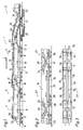
- Bulk loading wagons 27 shown in FIGS. 2 and 3 each have a chassis frame 3o which can be moved via running gear 28 on a track 29 and has a car body 31 which is divided into two car body halves 33, 34 by a partition wall 32 running centrally in the longitudinal direction of the car.
- Each of these car body halves 33, 34 is equipped with its own conveyor 39, 39, each consisting of a floor conveyor 35, 36 and a raised and projecting transfer conveyor 37, 38, which can be driven independently of one another in the opposite direction by a motor 41 (see full and dashed arrows).
- Each floor conveyor 35, 36 is extended at the opposite end by a transfer conveyor 37 and 38, respectively.
- both halves 33, 34 of the bulk goods loading wagon 27 are filled with new ballast, which is transported to the work station or broaching machine via the conveying devices 39, 40.
Landscapes
- Engineering & Computer Science (AREA)
- Architecture (AREA)
- Civil Engineering (AREA)
- Structural Engineering (AREA)
- Machines For Laying And Maintaining Railways (AREA)
- Loading Or Unloading Of Vehicles (AREA)
- Ship Loading And Unloading (AREA)
- Filling Or Emptying Of Bunkers, Hoppers, And Tanks (AREA)
- Structure Of Belt Conveyors (AREA)
- Handcart (AREA)
Description
Die Erfindung betrifft einen Schüttgutverladewagen nach dem Oberbegriff des Anspruches 1.The invention relates to a bulk loading wagon according to the preamble of claim 1.
Ein derartiger Schüttgutverladewagen ist aus der EP-A1-o 3o3 o37 bekannt. Bei diesem bekannten Schüttgutverladewagen besteht die erste Fördereinrichtung aus einem im Bodenbereich des Wagenkastens angeordneten Bodenförderband und einem diesem zugeordneten, an einem Ende des Schüttgutverladewagens angeordneten, geneigt verlaufenden Übergabeförderband. Die zweite Fordereinrichtung besteht aus einem Förderband, das oberhalb des Wagenkastens angeordnet ist und ein überkragendes, nach unten geneigt verlaufendes Ende aufweist. Die Fördereinrichtungen können entgegengesetzt angetrieben werden. Hierdurch ist es möglich, im Bodenbereich Abraum abzufördern und im oberen Bereich neues Material zur Aushubstelle zu fördern. Außerdem ist ein Speichern von Material im Wagenkasten möglich. Der Wagenkasten kann eine in Wagenlängsrichtung verlaufende mittige Trennwand aufweisen, durch die der Wagenkasten in zwei Wagenkastenhälften aufgeteilt wird, die unterschiedliches Schüttgut aufnehmen können.Such a bulk goods loading wagon is known from EP-A1-o 3o3 o37. In this known bulk goods loading wagon, the first conveying device consists of a floor conveyor belt arranged in the floor area of the car body and an inclined transfer conveyor belt associated therewith and arranged at one end of the bulk goods loading wagon. The second conveyor consists of a conveyor belt, which is arranged above the car body and has an overhanging, downwardly inclined end. The conveyors can be driven in opposite directions. This makes it possible to remove overburden in the bottom area and to convey new material to the excavation site in the upper area. It is also possible to store material in the car body. The car body can have a central partition running in the longitudinal direction of the car, through which the car body is divided into two car body halves, which can accommodate different bulk goods.
Aus der AT-PS 378 973 ist ein für die Eingliederung in einen aus mehreren derartigen Schüttgutverladewagen bestehenden Zugverband bekannt, der einen oben offenen, am Fahrgestellrahmen befestigten Wagenkasten zum Speichern des Schüttgutes und eine diesem zugeordnete, zumindest teilweise im unteren Bereich des Wagenkastens und in Wagenlängsrichtung verlaufende Fördereinrichtung aufweist. Die beiden in Wagenlängsrichtung voneinander distanzierten Enden der Fördereinrichtung sind in unterschiedlicher Höhe angeordnet, so daß bei Kupplung zweier derartiger Schüttgutverladewagen je ein Ende der einen Fördereinrichtung das zugeordnete Ende der anderen Fördereinrichtung über- bzw. untergreift. Bei der Eingliederung eines derartigen Schüttgutverladewagens in einen aus mehreren derartigen Wagen bestehenden Zugverband bilden die speziellen Fördereinrichtungen der in beliebiger Anzahl mit einer den Einsatzbedingungen entsprechenden Speicherkapazität zusammengestellten Verladewagen eine durchgehende Förderstraße, mit der das in einem Endbereich des Zugverbandes auf einen Verladewagen abgeworfene Schüttgut ohne Zusatzeinrichtung bis zum gegenüberliegenden Ende des Zugverbandes zur Speicherung transportierbar ist. Damit sind die Verladewagen fortlaufend bis zum letzten im Bereich der Beladestelle gelegenen Wagen befüllbar.From AT-PS 378 973 a for the integration into a train consisting of several such bulk loading wagons is known, the open top, attached to the chassis frame for storing the bulk goods and an associated, at least partially in the lower area of the car body and in the longitudinal direction has running conveyor. The two ends of the conveying device, which are spaced apart from one another in the longitudinal direction of the carriage, are arranged at different heights, so that when two such bulk goods loading wagons are coupled, one end of one conveying device overlaps or underlaps the associated end of the other conveying device. When such a bulk loading wagon is incorporated into a train set consisting of several such wagons, the special conveying devices form any of them Number of loading wagons assembled with a storage capacity corresponding to the operating conditions, a continuous conveyor line with which the bulk goods dropped onto a loading wagon in an end region of the train assembly can be transported to the opposite end of the train assembly for storage without additional equipment. This means that the loading wagons can be filled up to the last wagon in the area of the loading point.
Durch die AT-PS 336 67o ist ebenfalls ein Schüttgutverladewagen zur Eingliederung in einen Abraumverladezug mit einem oben offenen, trichterförmig ausgebildeten Wagenkasten zum Speichern des Schüttgutes bekannt. Im oberen Endbereich des Wagenkastens sind zwei Förderbänder zum Transport des Schüttgutes vorgesehen, die durch an der Seitenwand angeordnete Führungen relativ zueinander in Wagenlängsrichtung verschiebbar gelagert sind. Damit ist die gesamte Wagenlänge zur Weiterbeförderung des Schüttgutes auf einen angeschlossenen Schüttgutverladewagen durch die Förderbänder überdeckbar. Zur Entladung sind im unteren Bereich der Wagenkasten-Seitenwand Entladeschurren vorgesehen. Eine derartige Förderbandkonstruktion ist relativ aufwendig und ermöglicht außerdem keine Entladung des gespeicherten Schüttgutes.AT-PS 336 67o also discloses a bulk goods loading wagon for incorporation into a spoil loading train with an open, funnel-shaped body for storing the bulk goods. In the upper end region of the car body, two conveyor belts for transporting the bulk material are provided, which are mounted so as to be displaceable relative to one another in the longitudinal direction of the car by guides arranged on the side wall. This means that the entire length of the wagon for further transport of the bulk goods can be covered by the conveyor belts on a connected bulk goods loading wagon. Unloading chutes are provided in the lower area of the side wall of the car body for unloading. Such a conveyor belt construction is relatively complex and also does not allow unloading of the stored bulk material.
Schließlich ist noch in der DE-OS 34 2o 826 ein Eisenbahnbauzug zur Entfernung der alten Schotterbettung und Einbringung von neuem Schotter und Kies bekannt. Dieser setzt sich aus einer Vielzahl von Materialwagen zur Speicherung des Schüttgutes zusammen, wobei an beiden Längsseiten jedes Materialwagens ein Endlosförderer zum Transport von Kies bzw. Schotter vorgesehen ist. Ein derartiger bekannter Bauzug erfordert jedoch eigene Ladegeräte, mit denen das Schüttgut auf den jeweiligen Endlosförderer transportierbar ist.Finally, in DE-OS 34 2o 826 a railway construction train for removing the old ballast bed and introducing new ballast and gravel is known. This consists of a large number of material trolleys for storing the bulk material, an endless conveyor for transporting gravel or crushed stone being provided on both long sides of each material trolley. However, such a known construction train requires its own chargers with which the bulk material can be transported on the respective endless conveyor.
Der Erfindung liegt die Aufgabe zugrunde, einen Schüttgutverladewagen der gattungsgemaßen Art für die Eingliederung in einen aus mehreren derartigen Wagen bestehenden Zugverband zu schaffen, mit welchem unter uneingeschränkter Beibehaltung einer selbsttätigen Entladung eine verbesserte Einsatzmöglichkeit gegeben ist.The invention has for its object to provide a bulk loading wagon of the generic type for incorporation into a train set consisting of several such wagons, with which an improved application is given while fully maintaining an automatic unloading.
Diese Aufgabe wird bei einem Schüttgutverladewagen der gattungsgemäßen Art durch die Merkmale im Kennzeichnungsteil des Anspruches 1 gelöst. Hierdurch ist es möglich, parallel zu dem durch den Einsatz der einen Fördereinrichtung durchführbaren Materialtransport in Richtung zur Baustelle mit Hilfe der anderen Fördereinrichtung weiteres, von der Baustelle abzutransportierendes Schüttgut zur Speicherung in mittlerweile geleerte Schüttgutverladewagen abzuwerfen. Damit kann reiner Förderbetrieb und alternativ Speicherbetrieb einerseits für zur Baustelle zu förderndes Material und andererseits für von der Baustelle abzuförderndes Material unabhängig voneinander jeweils gesondert durchgeführt werden. Die erfindungsgemäß ausgestalteten Schüttgutverladewagen sind also außerordentlich vielseitig einsetzbar.This object is achieved in a bulk loading wagon of the generic type by the features in the characterizing part of claim 1. This makes it possible, parallel to the material transport that can be carried out through the use of one conveying device, towards the construction site with the help of the other conveying device to drop further bulk goods to be transported away from the construction site for storage in now empty bulk goods loading wagons. Pure conveying operation and alternatively storage operation on the one hand for material to be conveyed to the construction site and on the other hand for material to be conveyed from the construction site can thus be carried out separately from one another. The bulk goods loading wagons designed according to the invention are therefore extremely versatile.
Durch die Ausgestaltung nach Anspruch 2 wird erreicht, daß je nach dem Status der Be- bzw. Entladung des Schüttgutverladewagens die Laufgeschwindigkeit der jeweiligen Fördereinrichtung optimal auf die zu erfüllende Aufgabe - Speicherung oder Transport von Schotter - abstimmbar ist.The embodiment according to
Durch die Weiterbildung nach Anspruch 3 werden einerseits der Speicherbetrieb und andererseits der reine Förderbetrieb unabhängig voneinander optimiert.The further development according to claim 3 optimizes storage operation on the one hand and purely production operation on the other hand independently.
Im folgenden wird die Erfindung anhand eines in der Zeichnung dargestellten Ausführungsbeispieles näher beschrieben.The invention is described in more detail below with reference to an embodiment shown in the drawing.
Es zeigen:
- Fig.1 eine Seitenansicht eines aus mehreren nicht erfindungsgemäß ausgebildeten Schüttgutverladewagen und einer Räummaschine bestehenden Zugverbandes zur Erläuterung des Einsatzfeldes eines Schüttgutverladewagens,
- Fig.2 eine Seitenansicht eines erfindungsgemäßen Schüttgutverladewagens im Zugverband (1) und
- Fig.3 eine Draufsicht auf den in Fig.2 gezeigten Zugverband.
- 1 shows a side view of a train assembly consisting of several bulk goods loading wagons not designed according to the invention and a broaching machine to explain the field of application of a bulk goods loading wagon,
- 2 shows a side view of a bulk loading wagon according to the invention in the train set (1) and
- 3 shows a plan view of the train set shown in FIG.
Ein in Fig.1 dargestellter Zugverband 1 besteht aus einer Räummaschine 2 und einer Anzahl dieser - in der durch einen Pfeil 3 angedeuteten Arbeitsrichtung - vorgeordneter Schüttgutverladewagen 4, die über Fahrwerke 5 auf einem Gleis 6 verfahrbar sind und jeweils einen an einem Fahrgestellrahmen 7 befestigten und oben offenen Wagenkasten 8 aufweisen. Jeder Schüttgutverladewagen 4 weist eine Fördereinrichtung 9 auf, die aus einem im Bodenbereich des Wagenkastens 8 in Wagenlängsrichtung verlaufenden Bodenförderband lo sowie einem an dieses in Förderrichtung anschließenden, hochgeführten und vorkragenden Übergabeförderband 11 besteht, welches um eine etwa vertikale Achse 12 verschwenkbar ist. Eine weitere Fördereinrichtung 13 ist oberhalb des Wagenkastens 8 über lösbare Stützen 14 mit Seitenwänden 15 des Wagenkastens 8 verbunden und kragt an beiden Längsenden gleich weit über das jeweilige Fahrwerk 5 vor. Die beiden Enden der Fördereinrichtung 13 sind unterschiedlich hoch angeordnet, damit im Übergabebereich 16 die benachbarten Enden der jeweiligen Fördereinrichtungen 13 übereinander zu liegen kommen. Die Energieversorgung von Antrieben 17 der Fördereinrichtungen 9,13 des Schüttgutverladewagens 4 erfolgt jeweils durch einen Motor 18.A train set 1 shown in FIG. 1 consists of a
Im Arbeitseinsatz wird der Zugverband 1 zur Arbeitsstelle verfahren, wobei die Schüttgutverladewagen 4 mit neuem Schotter gefüllt sind. Mittels einer Räumkette 19 wird alter Schotter 2o von der Räummaschine 2 - unter Bildung einer Aushubstelle 21 - hochgefördert und auf das Abraumförderband 22 geworfen. Dieses transportiert den Schotter zur oberen Fördereinrichtung 13 des an die Räummaschine 2 gekuppelten Schüttgutverladewagens 4. Ein für die Überstellfahrt abknickbares Ende 23 des Abraumförderbandes 22 ist dabei so angeordnet, daß es das Ende der anschließenden oberen Fördereinrichtung 13 entsprechend überlappt. Während nun der alte Schotter 2o über die obere Fördereinrichtung 13 in Richtung zum vorderen Ende des Zugverbandes 1 transportiert wird, wird gleichzeitig neuer Schotter 24 aus den vollen Schüttgutverladewagen 4 über die unteren Fördereinrichtungen 9 in Richtung zur Räummaschine 2 befördert und mittels eines Förderbandes 25 hinter der Aushubstelle 21 in das Gleis 6 eingebracht (siehe kleine Pfeile in Fig.1). Diese Entleerung erfolgt unter Ausnützung der eine durchgehende Förderstraße bildenden unteren Fördereinrichtungen 9 in allen Schüttgutverladewagen 4 gleichzeitig. Der dadurch im vordersten Schüttgutverladewagen 4 zuerst entstehende Leerraum wird parallel zur Entleerung kontinuierlich mit dem über die oberen Fördereinrichtungen 13 herangebrachten alten Schotter 2o wieder aufgefüllt. Zu diesem Zweck ist ein in Arbeitsrichtung vorderes Ende 26 der oberen Fördereinrichtung 13 des vordersten Schüttgutverladewagens 4 verkürzt ausgebildet, so daß der alte Schotter 2o auf die untere Fördereinrichtung 9 desselben Schüttgutverladewagens 4 abgeworfen wird. Durch die jeweiligen Antriebe 17 sind die Laufgeschwindigkeiten der Fördereinrichtungen 9 bzw. 13 je nach Füllzustand der Schüttgutverladewagen 4 aufeinander abstimmbar.In the course of work, the train set 1 is moved to the work site, the bulk
In Fig.2 und 3 dargestellte Schüttgutverladewagen 27 weisen jeweils einen über Fahrwerke 28 auf einem Gleis 29 verfahrbaren Fahrgestellrahmen 3o mit einem Wagenkasten 31 auf, der durch eine mittig in Wagenlängsrichtung verlaufende Trennwand 32 in zwei Wagenkastenhälften 33,34 geteilt wird. Jede dieser Wagenkastenhälften 33,34 ist mit einer eigenen, jeweils aus einem Bodenförderband 35,36 und einem hochgeführten und vorkragenden Übergabeförderband 37,38 bestehenden Fördereinrichtung 39,4o ausgestattet, die durch einen Motor 41 voneinander unabhängig in entgegengesetzter Richtung antreibbar sind (siehe volle und strichlierte Pfeile). Dabei ist jedes Bodenförderband 35,36 am jeweils gegenüberliegenden Ende durch ein Übergabeförderband 37 bzw. 38 verlängert. Am rechten Ende des durch die benachbarten Schüttgutverladewagen 27 angedeuteten Zugverbandes befindet sich beispielsweise eine nicht gezeigte Räummaschine, während am anderen, linken Ende ein ebenfalls nicht dargestelltes Umkehrförderband den Schotterfluß von der einen in die andere Richtung - d.h. von einer Fördereinrichtung 39 bzw. 4o auf die andere - umlenkt. Zu Einsatzbeginn sind beide Wagenkastenhälften 33,34 der Schüttgutverladewagen 27 mit neuem Schotter gefüllt, der über die Fördereinrichtungen 39,4o zur Arbeitsstelle bzw. Räummaschine transportiert wird. Da diese Entleerung - unter jeweiliger Weitergabe des Schotters mit Hilfe der Übergabeförderbänder 37,38 an den anschließenden Verladewagen 27 - gleichzeitig in allen Verladewagen 27 erfolgt, entsteht sofort in der unmittelbar an die Räummaschine anschließenden Wagenkastenhälfte 33 Leerraum. In diesen wird der durch die Räummaschine ausgehobene alte Schotter kontinuierlich abgeworfen und in die mittlerweile entstehenden weiteren Leerräume weitertransportiert (siehe volle Pfeile in Fig.3). Wird kurz vor Beendigung des Arbeitseinsatzes der neue Schotter bereits aus der letzten, unmittelbar an die Räummaschine anschließenden Wagenkastenhälfte 34 entnommen, sind die restlichen Wagenkastenhälften 33,34 bereits mit altem Schotter aufgefüllt.
Claims (3)
- A bulk material loading wagon for incorporation into a train formation consisting of several such wagons, with an open-topped wagon body (31) attached to the undercarriage frame (30) for storing the bulk material, with a first conveyor (39) associated therewith which extends at least partially in the base region of the wagon body (31) and in the longitudinal direction of the wagon and of which the two ends distanced from each other in the longitudinal direction of the wagon are arranged at different heights, so that when two such bulk material loading wagons (27) are coupled, the elevated end of one conveyor (39) overlaps the lower end of the adjoining conveyor (39), and with a second conveyor (40) for transporting bulk material which is associated with the wagon body (31) and independent of the first conveyor (39) and the two ends of which are likewise arranged at different heights, so that the ends of the conveyors (40) which are adjacent when two such bulk material loading wagons (27) are coupled come to lie one above the other, wherein the wagon body (31) has a partition (32) extending centrally in the longitudinal direction of the wagon, and wherein the first and the second conveyor (39, 40) are designed for transporting bulk material in opposite directions, characterized in that the first conveyor (39) is arranged in one wagon body half (33) defined by the partition (32) and the second conveyor (40) is arranged at least partially in the base region of the other wagon body half (34).
- A bulk material loading wagon according to claim 1, characterized in that the drives of each conveyor are designed for switching over from a slower storage speed to a faster transport speed.
- A bulk material loading wagon according to claim 1 or 2, characterized in that each conveyor consists of a base conveyor belt (35, 36) and an elevated and projecting transfer conveyor belt (37,38).
Applications Claiming Priority (2)
| Application Number | Priority Date | Filing Date | Title |
|---|---|---|---|
| AT0035190A AT394530B (en) | 1990-02-15 | 1990-02-15 | Bulk goods loading wagon |
| AT351/90 | 1990-02-15 |
Publications (2)
| Publication Number | Publication Date |
|---|---|
| EP0442094A1 EP0442094A1 (en) | 1991-08-21 |
| EP0442094B1 true EP0442094B1 (en) | 1994-02-09 |
Family
ID=3488312
Family Applications (1)
| Application Number | Title | Priority Date | Filing Date |
|---|---|---|---|
| EP90124389A Expired - Lifetime EP0442094B1 (en) | 1990-02-15 | 1990-12-17 | Bulk goods handling wagon |
Country Status (10)
| Country | Link |
|---|---|
| US (1) | US5151002A (en) |
| EP (1) | EP0442094B1 (en) |
| JP (1) | JP2739777B2 (en) |
| CN (1) | CN1019661B (en) |
| AT (1) | AT394530B (en) |
| AU (1) | AU635111B2 (en) |
| CA (1) | CA2036019C (en) |
| DE (1) | DE59004557D1 (en) |
| DK (1) | DK0442094T3 (en) |
| ES (1) | ES2048949T3 (en) |
Cited By (1)
| Publication number | Priority date | Publication date | Assignee | Title |
|---|---|---|---|---|
| EP1083262A2 (en) | 1999-09-10 | 2001-03-14 | Franz Plasser Bahnbaumaschinen-Industriegesellschaft m.b.H. | Method for loading and unloading a vehicle of a transport train and vehicle therefor |
Families Citing this family (20)
| Publication number | Priority date | Publication date | Assignee | Title |
|---|---|---|---|---|
| CZ278838B6 (en) * | 1992-02-05 | 1994-07-13 | Mechanizace Tratoveho Hospod P | Set for catching and transportation of ballast, waste or another loose material |
| EP0599799B1 (en) * | 1992-11-18 | 1996-12-18 | Franz Plasser Bahnbaumaschinen-Industriegesellschaft m.b.H. | Loading wagon for transporting bulk material |
| EP0838383B1 (en) * | 1996-10-22 | 2002-01-02 | Franz Plasser Bahnbaumaschinen-Industriegesellschaft m.b.H. | Bulk goods handling wagon |
| DE59709223D1 (en) * | 1996-11-20 | 2003-03-06 | Plasser Bahnbaumasch Franz | A bulk material |
| DE10118393B4 (en) * | 2001-04-12 | 2004-02-19 | Gsg Knape Gleissanierung Gmbh | Rail-accessible conveying and silo wagons, transport trains and processes for receiving, temporarily storing and delivering materials in connection with track construction work |
| AT6219U3 (en) * | 2002-07-23 | 2004-07-26 | Plasser Bahnbaumasch Franz | METHOD FOR LOADING A LOADING TRAIN |
| US20050281643A1 (en) * | 2004-03-01 | 2005-12-22 | Villar Christopher M | Conveyor system for loading hopper cars of dump train and associated methods |
| US20090035110A1 (en) * | 2007-08-03 | 2009-02-05 | Woods Jr James D | Backfilling apparatus with dual telescopically positionable material dispensers |
| ITMI20080230A1 (en) * | 2008-02-13 | 2009-08-14 | Rail Technology Llc | RAILWAY TRANSPORTATION WAGON PARTICULARLY FOR CONVOGLI A VALLE OF RAILWAY RIVERS |
| DE202009011149U1 (en) * | 2009-08-14 | 2009-11-12 | Zürcher, Ralf | Device for conveying materials in track construction |
| DE102009037568B3 (en) * | 2009-08-14 | 2011-02-03 | Zürcher, Ralf | Device for material handling in track construction, has coach for accommodating material, where coach is movable on track |
| DE102010007513B4 (en) * | 2010-02-11 | 2012-01-19 | Ralf Zürcher | Cart for conveying material in track construction |
| DE102011014266B4 (en) * | 2011-03-17 | 2013-08-29 | Ralf Zürcher | Between trolley |
| BR112013029455B1 (en) * | 2011-05-16 | 2020-12-15 | K & K Maschinenentwicklungs Gmbh & Co. Kg | RAIL TRANSPORT METHOD |
| FR2998589B1 (en) * | 2012-11-23 | 2018-02-02 | Europeenne De Travaux Ferroviaires (Etf) | DOUBLE FLOW AND DOUBLE SENSE BREAKER AND METHODS FOR RENEWING BALLAST AND TRAVERSES. |
| US9868451B2 (en) | 2013-03-15 | 2018-01-16 | Georgetown Rail Equipment Company | Self-unloading aggregate train |
| AT515413B1 (en) * | 2014-03-25 | 2015-09-15 | Plasser & Theurer Export Von Bahnbaumaschinen Gmbh | Method for rehabilitating a ballast bed of a track |
| EA032228B1 (en) * | 2014-05-20 | 2019-04-30 | Плассер Энд Тойрер Экспорт Фон Банбаумашинен Гезельшафт М.Б.Х. | Bulk material loading wagon |
| EP3215408B1 (en) | 2014-11-05 | 2021-01-20 | Herzog Railroad Services, Inc. | Material transport and distribution consist with controlled gated hopper cars and conveyor systems |
| AT517048B1 (en) * | 2015-04-13 | 2018-12-15 | Plasser & Theurer Export Von Bahnbaumaschinen Gmbh | Storage trolley for bulk goods |
Family Cites Families (16)
| Publication number | Priority date | Publication date | Assignee | Title |
|---|---|---|---|---|
| GB583717A (en) * | 1944-11-21 | 1946-12-30 | Angus Wellesley Duncan | Loading regulator |
| US3064837A (en) * | 1960-04-13 | 1962-11-20 | Columbus Mckinnon Corp | Surge car |
| US3498486A (en) * | 1968-02-09 | 1970-03-03 | Jesse H Freeman Jr | Multiple hopper vehicle |
| US3529738A (en) * | 1968-07-29 | 1970-09-22 | Charles L Hunt | Vehicle having improved unloader mechanism |
| AT336670B (en) * | 1973-01-12 | 1977-05-25 | Plasser Bahnbaumasch Franz | MOBILE SILO CARRIAGE, RAILWAY CARRIAGE AND DGL. WITH A LOADING OR MATERIAL SUPPLY DEVICE |
| DD155626A1 (en) * | 1980-12-22 | 1982-06-23 | Herbert Schmidt | RAIL-CONTAINED TRANSPORT CAR FOR SCHUETTGUETER |
| AT378973B (en) * | 1983-03-11 | 1985-10-25 | Plasser Bahnbaumasch Franz | SCHUETTGUTLADWAGEN, ESPECIALLY FOR THE WASTE LOADING OF A GRAVEL BED CLEANING MACHINE |
| DE3312492A1 (en) * | 1982-09-23 | 1984-03-29 | Franz Plasser Bahnbaumaschinen-Industriegesellschaft mbH, 1010 Wien | SCHUETTGUTLADWAGEN, ESPECIALLY FOR THE WASTE LOADING OF A GRAVEL BED CLEANING MACHINE |
| DD212544A1 (en) * | 1982-12-16 | 1984-08-15 | Deutsche Reichsbahn | RAIL-CONTAINED TRANSPORT CAR FOR SCHUETTGUETER |
| AT377030B (en) * | 1983-06-13 | 1985-01-25 | Wageneder Sbm Gmbh | RAILWAY CONSTRUCTION TRAIN FOR THE INSTALLATION OF A NEW BED IN RAILWAYS |
| US4925356A (en) * | 1985-06-06 | 1990-05-15 | Snead Edwin D | Self-unloading train for bulk commodities |
| DD249298A1 (en) * | 1986-05-20 | 1987-09-02 | Deutsche Reichsbahn | EXISTING TRANSPORT TRAIN CONSISTING OF RAIL-LINKED SHOE CAR |
| AT389333B (en) * | 1986-09-08 | 1989-11-27 | Plasser Bahnbaumasch Franz | ROLLABLE TRAILER LOADING CARRIAGE ARRANGEMENT WITH CONTROLLED UNLOADING CHEESES |
| DE3640916C2 (en) * | 1986-11-29 | 1998-07-16 | Stetter Gmbh | Method and device for producing concrete in a tunnel |
| IT1214197B (en) * | 1987-08-04 | 1990-01-10 | Danieli Off Mecc | SYSTEM FOR FOOD AND EVACUATION IN CONTINUOUS MATERIALS IN RENOVATION OPERATIONS RAILWAY AND SIMILAR PLATFORMS. |
| US5029532A (en) * | 1988-12-22 | 1991-07-09 | Snead Edwin De S | Control cab |
-
1990
- 1990-02-15 AT AT0035190A patent/AT394530B/en not_active IP Right Cessation
- 1990-12-17 EP EP90124389A patent/EP0442094B1/en not_active Expired - Lifetime
- 1990-12-17 DE DE90124389T patent/DE59004557D1/en not_active Expired - Fee Related
- 1990-12-17 ES ES90124389T patent/ES2048949T3/en not_active Expired - Lifetime
- 1990-12-17 DK DK90124389.9T patent/DK0442094T3/en not_active Application Discontinuation
- 1990-12-25 JP JP2406012A patent/JP2739777B2/en not_active Expired - Fee Related
-
1991
- 1991-01-31 US US07/648,214 patent/US5151002A/en not_active Expired - Fee Related
- 1991-02-08 CA CA002036019A patent/CA2036019C/en not_active Expired - Fee Related
- 1991-02-09 CN CN91101043A patent/CN1019661B/en not_active Expired
- 1991-02-14 AU AU71060/91A patent/AU635111B2/en not_active Ceased
Cited By (1)
| Publication number | Priority date | Publication date | Assignee | Title |
|---|---|---|---|---|
| EP1083262A2 (en) | 1999-09-10 | 2001-03-14 | Franz Plasser Bahnbaumaschinen-Industriegesellschaft m.b.H. | Method for loading and unloading a vehicle of a transport train and vehicle therefor |
Also Published As
| Publication number | Publication date |
|---|---|
| CN1054048A (en) | 1991-08-28 |
| ATA35190A (en) | 1991-10-15 |
| AT394530B (en) | 1992-04-27 |
| AU7106091A (en) | 1991-08-22 |
| ES2048949T3 (en) | 1994-04-01 |
| JPH0481356A (en) | 1992-03-16 |
| CA2036019A1 (en) | 1991-08-16 |
| DK0442094T3 (en) | 1994-06-06 |
| JP2739777B2 (en) | 1998-04-15 |
| CN1019661B (en) | 1992-12-30 |
| AU635111B2 (en) | 1993-03-11 |
| EP0442094A1 (en) | 1991-08-21 |
| CA2036019C (en) | 2000-08-22 |
| US5151002A (en) | 1992-09-29 |
| DE59004557D1 (en) | 1994-03-24 |
Similar Documents
| Publication | Publication Date | Title |
|---|---|---|
| EP0442094B1 (en) | Bulk goods handling wagon | |
| DE3312492C2 (en) | ||
| DE3711707C2 (en) | ||
| AT398213B (en) | MACHINE FOR RECEIVING AND DISTRIBUTING THE BEDGING BALL | |
| EP0599799B1 (en) | Loading wagon for transporting bulk material | |
| DE2348015C2 (en) | Mobile silo wagons, railway wagons and the like with a belt conveyor arrangement bridging the silo opening in the track direction | |
| EP0838383B1 (en) | Bulk goods handling wagon | |
| AT409617B (en) | STORAGE TROLLEY FOR STORING BULK MATERIAL | |
| EP0844330B1 (en) | Bulk goods handling wagon | |
| DE4237712C2 (en) | Plant for the production of a formation protection layer | |
| DE2713634A1 (en) | MOBILE MACHINE ARRANGEMENT FOR TRANSPORTING BULK GOODS | |
| DE3050908C2 (en) | ||
| AT400836B (en) | BULK LOADING WAGON | |
| AT378973B (en) | SCHUETTGUTLADWAGEN, ESPECIALLY FOR THE WASTE LOADING OF A GRAVEL BED CLEANING MACHINE | |
| DE3151030A1 (en) | MOBILE PLANT FOR PRODUCING A BETWEEN PLANUM AND BULLET BED OF A PROTECTIVE LAYER | |
| DE4213925C2 (en) | Wagon train for storing and transporting bulk goods | |
| EP1083262A2 (en) | Method for loading and unloading a vehicle of a transport train and vehicle therefor | |
| EP1312715A2 (en) | Track maintenance vehicle | |
| EP0429713B1 (en) | Mobile railway installation for the transport of bulk material | |
| DE3420836A1 (en) | Railway construction train for introducing a new track bed in track installations | |
| DD249298A1 (en) | EXISTING TRANSPORT TRAIN CONSISTING OF RAIL-LINKED SHOE CAR | |
| AT398592B (en) | LOADING TROLLEYS TO RECEIVE, RETURN AND SHIP BULK GOODS | |
| EP1254987A2 (en) | Method for renewing the railway ballast and machine | |
| DE4435853A1 (en) | Conveyor for moving rectangular sliver cans avoiding obstruction | |
| DD212544A1 (en) | RAIL-CONTAINED TRANSPORT CAR FOR SCHUETTGUETER |
Legal Events
| Date | Code | Title | Description |
|---|---|---|---|
| PUAI | Public reference made under article 153(3) epc to a published international application that has entered the european phase |
Free format text: ORIGINAL CODE: 0009012 |
|
| AK | Designated contracting states |
Kind code of ref document: A1 Designated state(s): BE CH DE DK ES FR GB IT LI NL SE |
|
| 17P | Request for examination filed |
Effective date: 19920122 |
|
| 17Q | First examination report despatched |
Effective date: 19930113 |
|
| GRAA | (expected) grant |
Free format text: ORIGINAL CODE: 0009210 |
|
| AK | Designated contracting states |
Kind code of ref document: B1 Designated state(s): BE CH DE DK ES FR GB IT LI NL SE |
|
| GBT | Gb: translation of ep patent filed (gb section 77(6)(a)/1977) |
Effective date: 19940207 |
|
| REF | Corresponds to: |
Ref document number: 59004557 Country of ref document: DE Date of ref document: 19940324 |
|
| REG | Reference to a national code |
Ref country code: ES Ref legal event code: FG2A Ref document number: 2048949 Country of ref document: ES Kind code of ref document: T3 |
|
| ITF | It: translation for a ep patent filed | ||
| ET | Fr: translation filed | ||
| REG | Reference to a national code |
Ref country code: DK Ref legal event code: T3 |
|
| PLBE | No opposition filed within time limit |
Free format text: ORIGINAL CODE: 0009261 |
|
| STAA | Information on the status of an ep patent application or granted ep patent |
Free format text: STATUS: NO OPPOSITION FILED WITHIN TIME LIMIT |
|
| EAL | Se: european patent in force in sweden |
Ref document number: 90124389.9 |
|
| 26N | No opposition filed | ||
| REG | Reference to a national code |
Ref country code: GB Ref legal event code: IF02 |
|
| PG25 | Lapsed in a contracting state [announced via postgrant information from national office to epo] |
Ref country code: IT Free format text: LAPSE BECAUSE OF NON-PAYMENT OF DUE FEES;WARNING: LAPSES OF ITALIAN PATENTS WITH EFFECTIVE DATE BEFORE 2007 MAY HAVE OCCURRED AT ANY TIME BEFORE 2007. THE CORRECT EFFECTIVE DATE MAY BE DIFFERENT FROM THE ONE RECORDED. Effective date: 20051217 |
|
| PGFP | Annual fee paid to national office [announced via postgrant information from national office to epo] |
Ref country code: NL Payment date: 20081125 Year of fee payment: 19 Ref country code: DK Payment date: 20081124 Year of fee payment: 19 Ref country code: CH Payment date: 20081124 Year of fee payment: 19 |
|
| PGFP | Annual fee paid to national office [announced via postgrant information from national office to epo] |
Ref country code: SE Payment date: 20081124 Year of fee payment: 19 Ref country code: BE Payment date: 20081124 Year of fee payment: 19 |
|
| PGFP | Annual fee paid to national office [announced via postgrant information from national office to epo] |
Ref country code: ES Payment date: 20081119 Year of fee payment: 19 Ref country code: FR Payment date: 20081124 Year of fee payment: 19 |
|
| PGFP | Annual fee paid to national office [announced via postgrant information from national office to epo] |
Ref country code: DE Payment date: 20081229 Year of fee payment: 19 |
|
| PGFP | Annual fee paid to national office [announced via postgrant information from national office to epo] |
Ref country code: GB Payment date: 20081029 Year of fee payment: 19 |
|
| PGRI | Patent reinstated in contracting state [announced from national office to epo] |
Ref country code: IT Effective date: 20090401 |
|
| PGFP | Annual fee paid to national office [announced via postgrant information from national office to epo] |
Ref country code: IT Payment date: 20071224 Year of fee payment: 18 |
|
| BERE | Be: lapsed |
Owner name: FRANZ *PLASSER BAHNBAUMASCHINEN- INDUSTRIEGESELLSC Effective date: 20091231 |
|
| REG | Reference to a national code |
Ref country code: NL Ref legal event code: V1 Effective date: 20100701 |
|
| EUG | Se: european patent has lapsed | ||
| REG | Reference to a national code |
Ref country code: CH Ref legal event code: PL |
|
| REG | Reference to a national code |
Ref country code: DK Ref legal event code: EBP |
|
| GBPC | Gb: european patent ceased through non-payment of renewal fee |
Effective date: 20091217 |
|
| REG | Reference to a national code |
Ref country code: FR Ref legal event code: ST Effective date: 20100831 |
|
| PG25 | Lapsed in a contracting state [announced via postgrant information from national office to epo] |
Ref country code: LI Free format text: LAPSE BECAUSE OF NON-PAYMENT OF DUE FEES Effective date: 20091231 Ref country code: BE Free format text: LAPSE BECAUSE OF NON-PAYMENT OF DUE FEES Effective date: 20091231 Ref country code: CH Free format text: LAPSE BECAUSE OF NON-PAYMENT OF DUE FEES Effective date: 20091231 Ref country code: NL Free format text: LAPSE BECAUSE OF NON-PAYMENT OF DUE FEES Effective date: 20100701 Ref country code: FR Free format text: LAPSE BECAUSE OF NON-PAYMENT OF DUE FEES Effective date: 20091231 |
|
| PG25 | Lapsed in a contracting state [announced via postgrant information from national office to epo] |
Ref country code: DE Free format text: LAPSE BECAUSE OF NON-PAYMENT OF DUE FEES Effective date: 20100701 |
|
| PG25 | Lapsed in a contracting state [announced via postgrant information from national office to epo] |
Ref country code: GB Free format text: LAPSE BECAUSE OF NON-PAYMENT OF DUE FEES Effective date: 20091217 |
|
| PG25 | Lapsed in a contracting state [announced via postgrant information from national office to epo] |
Ref country code: DK Free format text: LAPSE BECAUSE OF NON-PAYMENT OF DUE FEES Effective date: 20100104 |
|
| REG | Reference to a national code |
Ref country code: ES Ref legal event code: FD2A Effective date: 20110301 |
|
| PG25 | Lapsed in a contracting state [announced via postgrant information from national office to epo] |
Ref country code: SE Free format text: LAPSE BECAUSE OF NON-PAYMENT OF DUE FEES Effective date: 20091218 |
|
| PG25 | Lapsed in a contracting state [announced via postgrant information from national office to epo] |
Ref country code: ES Free format text: LAPSE BECAUSE OF EXPIRATION OF PROTECTION Effective date: 20101218 |
|
| PGRI | Patent reinstated in contracting state [announced from national office to epo] |
Ref country code: IT Effective date: 20090401 |
|
| PG25 | Lapsed in a contracting state [announced via postgrant information from national office to epo] |
Ref country code: ES Free format text: LAPSE BECAUSE OF EXPIRATION OF PROTECTION Effective date: 20091218 |